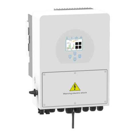
Simpson SCGH5500 User manual

Part Number 7115316 / ENGLISH REV F - 07/22/2021
Models covered: SCGH5500 / SCGH8500 / SCGH8500E
SAVE THIS MANUAL FOR FUTURE REFERENCE
USE AND CARE MANUAL
GENERATOR
READ THIS MANUAL CAREFULLY BEFORE OPERATION
Failure to follow the instructions and safety precautions in this manual can result
in property damage, serious injury and/or death.
NOTE: Photographs and line drawings used in this manual are for
reference only and may not represent your specic model.

Page II REV F - 07/22/2021Part Number 7115316 / ENGLISH
NOTES
This product and the engine exhaust can expose you to chemicals which are known to
the state of California to cause cancer, birth defects, or other reproductive harm. For more
information on California Proposition 65, go to www.P65Warnings.ca.gov.
CALIFORNIA PROPOSITION 65 WARNING
POLYCYCLIC AROMATIC HYDROCARBON WARNING
The air lter element and air box assembly may contain polycyclic aromatic hydrocarbons
(PAHs). Some PAHs may cause cancer. To avoid exposure to PAHs, wear gloves when
performing air lter maintenance.

Page 1 REV F - 07/22/2021Part Number 7115316 / ENGLISH
SAVE THIS MANUAL FOR FUTURE USE
Write down the model number, serial number, and purchase date of this product in the spaces
provided below then keep this manual with the purchase receipt(s) for future reference.
Keep this manual for future reference. This manual should be considered a permanent part
of the product and stay with it. This manual should be available to anyone operating the
product(s) it covers. This manual should remain with the product(s) it covers if sold to a new
owner. If the manual becomes damaged, lost, or otherwise unusable, you may download
a new copy from the product pages at www.simpsoncleaning.com or contact customer
support by calling 1-877-362-4271.
Model Data Decals
Model Number:
Serial Number:
Purchase Date:

Page 2 REV F - 07/22/2021Part Number 7115316 / ENGLISH
TABLE OF CONTENTS
SAFETY INSTRUCTIONS ...............................................................4
Hazard Alert Symbols .......................................................................................................4
Emission Information ........................................................................................................5
Special Requirements.......................................................................................................5
DISCLAIMERS .................................................................................5
ASSEMBLY ......................................................................................6
Unpacking.........................................................................................................................6
Installing the Wheels.........................................................................................................6
Assembling and Installing the Support Bracket ................................................................7
Connecting Battery (Electric Start Models Only)...............................................................8
COMPONENT LOCATION ...............................................................9
CONTROL PANELS ......................................................................11
SCGH5500......................................................................................................................11
SCGH8500......................................................................................................................11
SCGH8500E ...................................................................................................................11
HOUR METER ...............................................................................12
Hour Meter......................................................................................................................12
IDLE CONTROL .............................................................................12
Idle Control......................................................................................................................12
OPERATING CHECKLIST .............................................................13
Location ..........................................................................................................................13
Operating Conditions ......................................................................................................14
Grounding .......................................................................................................................15
Connecting Generator to the Electrical System of a Building .........................................15
Checking Fuel.................................................................................................................16
STARTING .....................................................................................18
Starting the Generator ....................................................................................................18
CONNECTING DEVICES ...............................................................20
Connecting Electrical Devices ........................................................................................20
Generator Load Capacity................................................................................................20
Generator Load Chart.....................................................................................................21

Page 3 REV F - 07/22/2021Part Number 7115316 / ENGLISH
SHUTTING OFF GENERATOR .....................................................22
MAINTENANCE .............................................................................23
Generator Maintenance ..................................................................................................23
Engine Maintenance .......................................................................................................23
Cleaning..........................................................................................................................23
Battery Maintenance (Electric Start Models Only) ..........................................................24
Engine Idle Adjustment ...................................................................................................24
TROUBLESHOOTING ...................................................................25
Generator Troubleshooting Chart ...................................................................................25
Engine Troubleshooting Chart ........................................................................................25
STORAGE AND TRANSPORTATION ...........................................26
Storing for Two Months or Less ......................................................................................26
Storing for More Than Two Months.................................................................................27
Transportation.................................................................................................................27
WIRING DIAGRAMS ......................................................................28
SCGH5500......................................................................................................................28
SCGH8500......................................................................................................................29
SCGH8500E ...................................................................................................................30
SPECIFICATIONS ..........................................................................31
Model Number: SCGH5500 / Item Number: 70053 ........................................................31
Model Number: SCGH8500 / Item Number: 70054 ........................................................31
Model Number: SCGH8500E / Item Number: 70055......................................................32

Page 4 REV F - 07/22/2021Part Number 7115316 / ENGLISH
This manual contains important safety information and instructions. Do not operate
this product until you have read, and completely understand all safety, operation, and
maintenance instructions listed in this manual. Failure to follow the information contained
in this manual will result in property damage, injury, and/or death.
NOTE: The warnings and precautions discussed in this manual cannot cover all conditions
and situations that may occur. The operator must understand awareness and caution are
factors which cannot be built into this product and so must be exercised by the operator.
READ THIS MANUAL BEFORE OPERATING
ADDITIONAL INSTRUCTIONS
Be sure to understand the safety symbols and denitions listed below. Each symbol
contains one of four words: DANGER, WARNING, CAUTION, NOTICE, indicating dierent
levels of hazard severity. These symbols are used throughout this manual and are followed
information about a specic hazard, the consequences of the hazard, and instructions on
how to avoid the hazard. Failure to heed these symbols and follow the instructions provided
with them will result in property damage, injury, and/or death.
Hazard Alert Symbols
Indicates an imminently dangerous situation, which if not
avoided, will result in property damage, serious injury, and/
or death.
Indicates a potentially hazardous situation, which if not
avoided, could result in property damage, serious injury, and/
or death.
Indicates a hazardous situation, which if not avoided, could
result in property damage and/or minor to moderate injury.
Indicates information considered important, but not directly
hazard related.
SAFETY INSTRUCTIONS
Along with this manual, be sure to read any additional instructions provided both on and
with the product, attached equipment, accessories, and the engine powering the product.
Pay careful attention to all additional safety rules and instructions on proper startup,
operation, and shutdown procedures. Always use any recommended protective apparel
that may be needed to operate the equipment safely.

Page 5 REV F - 07/22/2021Part Number 7115316 / ENGLISH
Emission Information
The Environmental Protection Agency (and California Air Resource Board of generators
certied to CA standards) requires that this generator comply with exhaust and evaporative
emission standards. Locate the emissions compliance decal on the engine to determine
what standards the generator meets and which warranty applies. This generator is certied
to operate on gasoline.
The emission control system includes the following components (if equipped):
●All information in this publication was based on the latest product information available
at the time of printing. The FNA Group reserves the right to change, alter, and/or
improve the product and this document at any time, without notice, and without incurring
any obligation.
● The pictures and gures in this manual should be used for reference only. There may be
dierences between the pictures and gures and the physical product.
● This generator may be equipped with a spark arrestor muer. If equipped, the spark
arrestor must be maintained in eective working order by the owner/operator. In the
State of California, a spark arrestor is required by law (Section 4442 of the California
Public Resources Code). Other states may have similar laws. Federal laws apply on
federal lands.
DISCLAIMERS
Air Induction System
●Intake pipe or manifold
●Air cleaner
Fuel System
●Carburetor
●Fuel tank and cap
●Fuel lines
●Evaporative vent lines
●Carbon canister
Ignition System
●Spark plug
●Ignition module
Exhaust System
●Exhaust manifold
● Muer
●Pulsed Air valve
●Catalyst
Special Requirements
●In some areas, generators are required to be registered with local utility companies.
●If the generator is used at a construction site, there may be additional regulations which
must be observed.
●There may be additional federal and/or state Occupational Safety and Health
Administration (OSHA) regulations, local codes, or ordinances that apply to the intended
use of the generator. Please consult a qualied electrician, electrical inspector, or the
local agency having jurisdiction in your area.

Page 6 REV F - 07/22/2021Part Number 7115316 / ENGLISH
1
2
3
4
ASSEMBLY
Unpacking
1. Place the shipping carton on a solid, at surface.
2. Carefully cut the top of the carton open.
3. Carefully cut each corner of the carton from top to bottom.
4. Lay each side of the carton at on the ground.
5. Remove everything from the carton.
Follow the steps outlined in this section to unpack and assemble your generator. If you have
any questions regarding the unpacking or assembly of your generator, please have your
model number and serial number ready, then contact customer support at 1-877-362-4271
Installing the Wheels
Slide the axle through the wheel, the rst washer, frame mounting hole, and the second
washer. Then insert the clip through the hole in the axle to secure the assembly. This
process must be done on both sides of the generator.
NOTE: Generator wheels are not intended for over-the-road use.
1. Axle
2. Wheel
3. Washers
4. Clip

Page 7 REV F - 07/22/2021Part Number 7115316 / ENGLISH
Assembling and Installing the Support Bracket
Assembling bracket: If rubber feet are not already installed on the onto the support bracket,
slide both M6x18 bolts through the rubber feet then through the support bracket, and tighten
M6 nuts onto the bolts to secure the assemblies.
Installing assembled bracket: Slide both M8x16 bolts through the support bracket and
frame, then tighten the M8 nuts onto the bolts to secure the assembly.
2
1
3
4
6
5
1. M6x18 bolts
2. Rubber feet
3. Support bracket
4. M6 nuts
5. M8x16 bolts
6. M8 nuts

Page 8 REV F - 07/22/2021Part Number 7115316 / ENGLISH
Connecting Battery (Electric Start Models Only)
NOTE: A battery is not included with the generator. A 12-volt, 14-amp, garden tractor style
battery is recommended. Please reference the engine manual for specic battery cranking
amp requirements. To connect the battery, you will need to install the battery cables by
following the steps outlined below. For battery location see the COMPONENT LOCATION
section of this manual.
ACID
Batteries contain sulfuric acid. Sulfuric acid is highly corrosive. Contact with skin can
cause severe burns; contact with eyes can cause permanent blindness; and accidental
ingestion can cause death. To avoid contact with sulfuric acid, always wear protective
equipment when handling batteries. If acid contacts skin, ush are with cool water for
10-15 minutes. Immediately remove contaminated clothing and thoroughly wash the
underlying skin.
2
1
1. Remove the retaining nut on the battery box* (A), remove the battery retainer (B), place
the battery in the tray (C), then replace the battery retainer and nut.
2. Remove battery terminal covers if applicable.
3. Connect black cable (1) to the negative (-) battery terminal with supplied bolt and nut.
4. Connect red cable (2) to the positive (+) battery terminal with supplied bolt and nut.
5. Make sure both the positive and negative connections are secure.
6. Slide the rubber boots over both terminals and connection hardware.
1. Negative (-) battery cable (black)
2. Positive (+) battery cable (red)
A B C
*See the Component Location section
of this manual for battery box location.

Page 9 REV F - 07/22/2021Part Number 7115316 / ENGLISH
6
4
23
5
1
9
7
11
10
1. Frame
2. Fuel level indicator
3. Fuel tank cap
4. Fuel tank
5. Handle
6. Air lter box
7. EVAP / carbon canister
8. Spark plug
9. Engine cylinder head
10.Wheels
11. Exhaust heat shield
COMPONENT LOCATION
8
NOTE: Line drawings used in this manual may not represent your specic model.

Page 10 REV F - 07/22/2021Part Number 7115316 / ENGLISH
14
16
15
12
19
18
17
20
12.Handle stop pin
13.Choke
14.Fuel valve
15.Starter recoil
16.Support bracket
17.Engine oil drain plug
18.Oil dipstick
19.Battery tray (electric start models only)
20.Control panel
21.Frame ground terminal
22.Spark arrestor (if equipped)
22
21
13
NOTE: Line drawings used in this manual may not represent your specic model.

Page 11 REV F - 07/22/2021Part Number 7115316 / ENGLISH
1. Engine control switch
2. Idle control switch
3. Hour meter
4. Main breakers SCGH5500 17.5 amp, SCGH8500 & SCGH8500E 30 amp
5. Circuit breakers 20 amp
6. 120v AC, single phase, 60hz duplex receptacle (5-20R)
7. 120v AC, single phase, 60hz receptacle (L5-30R)
8. Ground terminal
9. 120v / 240v AC, single phase, 60hz receptacle (L14-30R)
SCGH5500
SCGH8500
CONTROL PANELS
SCGH8500E
8
8
8
9
9
9
7
7
7
4
4
4
1
1
1
2
2
2
6
6
6
3
3
3
5
5

Page 12 REV F - 07/22/2021Part Number 7115316 / ENGLISH
Hour Meter
The hour meter keeps track of the time the generator is running. The hour glass icon ashes
when the engine is running to signify the meter is tracking the hours of operation. The
digital time display shows the recorded hours of operation. For hour meter location see the
COMPONENT LOCATION section of this manual.
Idle Control
The idle control feature automatically reduces the engine speed when there is no electric
load on the generator. The lower engine idle speed saves fuel, reduces engine wear, and
lowers noise. The engine speed will automatically increase when an electric load is applied
to the generator.
To activate the idle control feature, turn the idle control switch on. To deactivate the idle control
feature, turn the idle control switch o. For idle control switch location, see the CONTROL
PANELS section in this manual. The idle control feature should be o before starting or
stopping the generator. Always allow the engine to warm up and the idle to stabilize before
turning the idle control switch on, or placing an electrical load on the generator.
21
1. Hour glass icon
2. Digital time display
HOUR METER
IDLE CONTROL
OFF
IDLE CONTROL SWITCH
ON

TOXIC FUMES
Engine exhaust contains carbon monoxide, an odorless, colorless, poisonous gas.
Running an engine indoors will kill you in minutes. Never use this product inside a house,
garage, or any other kind of enclosure even if doors and windows are open. Run the
engine outside at least twenty (20) feet or six (6) meters away from windows, doors, and
vents. Carefully consider wind direction and air currents when using this product outside
to avoid breathing in engine exhaust. Always use a carbon monoxide detector in any
occupied buildings near the running engine.
Page 13 REV F - 07/22/2021Part Number 7115316 / ENGLISH
OPERATING CHECKLIST
Location
Only use the generator outside in a well-ventilated area and always carefully consider wind
and air currents when running. Place the generator on a level surface before any operation
and provide two (2) feet clearance on all sides of the engine while operating.
●Never use the generator inside a house, garage, or any other kind of enclosure, even if
doors and windows are open.
●Install a carbon monoxide detector in any occupied buildings near the running engine.
●If you experience headache, nausea, dizziness, sleepiness, or weakness while the
generator is running, move to fresh air and seek medical attention immediately.

Page 14 REV F - 07/22/2021Part Number 7115316 / ENGLISH
INSPECT BEFORE OPERATING
MOVING PARTS
This product has many parts that move at high speeds. Moving parts can cause crushing
injuries, broken bones, severe lacerations, and/or traumatic amputations. To prevent
injury, never place ngers, hands, feet, or other body parts near running engine. Never
operate product with covers, shrouds, or other guards removed. Do not wear loose-tting
clothing, dangling drawstrings, or any other hanging items that could become entangled
in moving parts while operating. Tie up long hair and remove jewelry before operating.
Failure to inspect this product before use could result in a hazardous situation resulting
in product damage serious injury and/or death. To avoid these hazards, inspect the
generator before each use. Check for loose or damaged parts, signs of oil or fuel leaks,
missing guards, plugged cooling vents, or any other condition that may aect proper
operation. Repair or replace all damaged or defective parts and keep all safety guards in
place and in proper working order before using the generator.
UNTRAINED OPERATION
Untrained persons, young children, and pets can be seriously injured or killed if allowed
to incorrectly operate or play with a running generator. Be sure anyone operating the
generator receives proper instructions, understands safe operation, and has read the
owner’s manual before operating this product. Do not let children operate the generator
without parental supervision. Keep young children and pets away from the generator
while it is running. Always turn the generator o before leaving the area.
Operating Conditions
Before starting engine, remove any excessive dirt and debris from cooling vents, exhaust,
and starter recoil areas. Then, check for loose or damaged parts, oil or fuel leaks, and/
or any other condition that may aect proper operation. Repair or replace all damaged or
defective parts immediately. Always keep all safety guards in place and in proper working
order. For safety reasons, the manufacturer recommends all maintenance and repairs be
performed by an authorized service center. Never move or tip the generator while operating.
Use generator only for its intended purpose. If you have questions about the proper use
of your generator, please contact customer support at 1-877-362-4271 or cservice@fna-
group.com.
HOT SURFACES
A running engine produces heat. The surfaces of the engine, related components, and
engine exhaust gas get hot enough to cause mild moderate burns or ignite materials
on contact. To avoid burns, do not touch engine surfaces or exhaust gases while
operating and allow engine to cool completely before moving, touching, or performing
any maintenance. To avoid a re, keep all ammable materials at least ve feet away
from all sides of the product.

Page 15 REV F - 07/22/2021Part Number 7115316 / ENGLISH
Grounding
Grounding the generator helps prevent electrical shock if a ground fault condition develops
in the generator or in connected electrical devices. Proper grounding also helps dissipate
static electricity, which often builds up in ungrounded devices. Grounding a generator
with a wheel kit installed is especially important. The generators covered in this manual
have two ground terminals, one on the frame and one on the control panels. For ground
terminal location(s) see the COMPONENT LOCATION section of this manual. It is strongly
recommend that you refer to NEC 250.34 (sections A,B, and C) and/or consult with a local
electrician for grounding requirements in your area before operating the generator.
GROUNDING
ELECTROCUTION
Do not connect devices with worn, frayed, bare, or otherwise damaged electrical cords
to the generator. Electrical shorts caused by damaged wiring can damage the generator
and touching live damaged electrical cords or bare wires will cause serious injury or
death. To avoid these electrocution hazards, inspect all electrical cords before using them
and do not use any cords that are damaged or showing bare wires.
Failure to properly ground your generator will create an electrical shock hazard that
could result in severe injury or death. To prevent an electric shock hazard, be sure to
provide the correct ground for the desired use of the generator per the National Electric
Code (NEC) 250.3 (sections A,B,and C) or consult with a local electrician to learn the
appropriate grounding requirements.
Connecting Generator to the Electrical System of a Building
Do not attempt to backfeed power into your house from the generator. Backfeeding is trying
to power your home by plugging the generator into a wall outlet. Backfeeding can damage
electrical devices in your home, start an electrical re, and cause severe injury or death to
utility workers and others on your electrical grid.
Using a transfer switch is recommended when connecting a generator directly to a building’s
electrical system. Connections for a portable generator to a building’s electrical system
must be made by a qualied electrician and in strict compliance with all national and local
electrical codes and laws.
Backfeeding can damage electrical devices in your home, start an electrical re, and
may cause severe injury or death to utility workers and others on your electrical grid.
To prevent backfeeding, do not plug the generator into your home’s outlets and have a
qualied electrician install the generator if used as a back up power source.
BACKFEEDING

Page 16 REV F - 07/22/2021Part Number 7115316 / ENGLISH
Gasoline vapor can build up inside the fuel tank creating pressure. This pressure may
increase when the engine is hot from running. Opening the fuel tank under pressure can
cause rapid escape of ammable vapors and possible fuel spills that may ignite from
contact with hot engine surfaces resulting in burn hazard. To avoid rapidly escaping fuel
vapor, always allow the engine to cool for at least two (2) minutes before removing fuel
cap and loosen the fuel cap slowly to relieve any pressure in the tank.
FUEL TANK PRESSURE
Checking Fuel
REFUELING
Gasoline is highly ammable and gasoline vapors are extremely explosive. Fire and
explosions can cause severe burns and/or death. Keep gasoline away from ames,
sparks, and other ignition sources. Refuel outdoors in a well-ventilated area with the
engine stopped and cool. Wipe up any spilled gasoline and allow engine to dry before
starting. Keep a re extinguisher handy while refueling. Do not operate engine with leaks
in the fuel system. Do not store gasoline near other ammable materials.
Old gasoline can create deposits that clog fuel systems causing hard starting and poor
performance. Damage caused by old fuel is not covered by warranty. To minimize
deposits, avoid old fuel related performance issues, and prevent costly repair work, do
not use gasoline that is older than 30 days.
OLD FUEL
Using gasoline with an alcohol blend greater than 10% (E10) will damage the engine.
Damage caused by using an alcohol blend of 15% (E15), 85% (E85), or any other alcohol
blend higher than 10% (E10) is not covered under warranty. To avoid engine damage
caused by an alcohol blend that is too high, use gasoline with 10% (E10) alcohol or less.
ALCOHOL BLENDS
The use of fuel system cleaning additives can damage the engine and fuel systems.
Damage caused by the use of fuel system cleaning additives is not covered by warranty.
To avoid engine and fuel system damage, do not use any fuel system cleaning additives.
FUEL ADDITIVES

Page 17 REV F - 07/22/2021Part Number 7115316 / ENGLISH
DO NOT OVERFILL FUEL TANK
Overlling the fuel tank can result in carbon canister damage (if equipped), poor engine
performance, and void the warranty. To avoid damaging the carbon canister, poor engine
performance, and voiding the warranty, do not ll the fuel tank above the maximum level.
1. Check fuel with generator on a level surface with the engine o.
2. Read fuel gauge and ll fuel tank if needed. For fuel gage location see the COMPONENT
LOCATION section of this manual.
3. Do not use gasoline that is older than 30 days. Use only clean and fresh regular
unleaded gasoline with a minimum octane rating of 87. Do not mix oil with gasoline. Do
not use gasoline that contains more than 10% ethyl alcohol. E15, E20, and E85 are not
approved fuels and should not be used.
4. Do not to ll the fuel tank above the maximum fuel level to allow room for fuel expansion.
For fuel capacity see the SPECIFICATIONS section of this manual.
Maximum Fuel Level
It is important to prevent gum deposits from forming in essential fuel system parts, such
as the carburetor, fuel lter, fuel hose or tank during storage. Alcohol-blended fuels (also
called gasohol, ethanol, or methanol) attract moisture, which leads to separation and
formation of acids during storage. Acidic fuel and gum deposits can damage the engine’s
fuel system while in storage. Eects of old, stale, or contaminated fuel are not covered
under warranty.
NOTE: Using a fuel stabilizer when storing gasoline will help prevent problems related
to ethanol alcohol in outdoor power equipment engines. Always follow the instructions
provided by the fuel stabilizer manufacturer to mix and use correctly.
GASOLINE STORAGE

OPENCLOSED
OFF
Page 18 REV F - 07/22/2021Part Number 7115316 / ENGLISH
ON
STARTING
Starting the Generator
1. Follow the steps in the OPERATING CHECKLIST section of this manual.
2. Make sure there are no devices plugged into the generator outlets.
3. Turn fuel valve to the ON position. For fuel valve location see the COMPONENT
LOCATION section of this manual.
4. Adjust choke as needed. For choke location see the COMPONENT LOCATION section
of this manual.
NOTE: The starting position of the choke will vary depending on the engine temperature. If
starting a cold engine, move the choke lever towards the closed position. If starting a warm
engine, move the choke lever towards the open position.
Attempting to start the engine incorrectly or using the generator incorrectly can result in
engine and/or generator damage, and may cause serious injury or death. To avoid engine
and/or generator damage and serious injury or death be sure to read, understand, and
follow the steps outlined in the OPERATING CHECKLIST section of this manual before
starting the engine, and follow all the guidelines for proper use of the generator.
OPERATING CHECKLIST
5. Turn the engine idle control switch to the o position.
This manual suits for next models
2
Table of contents

