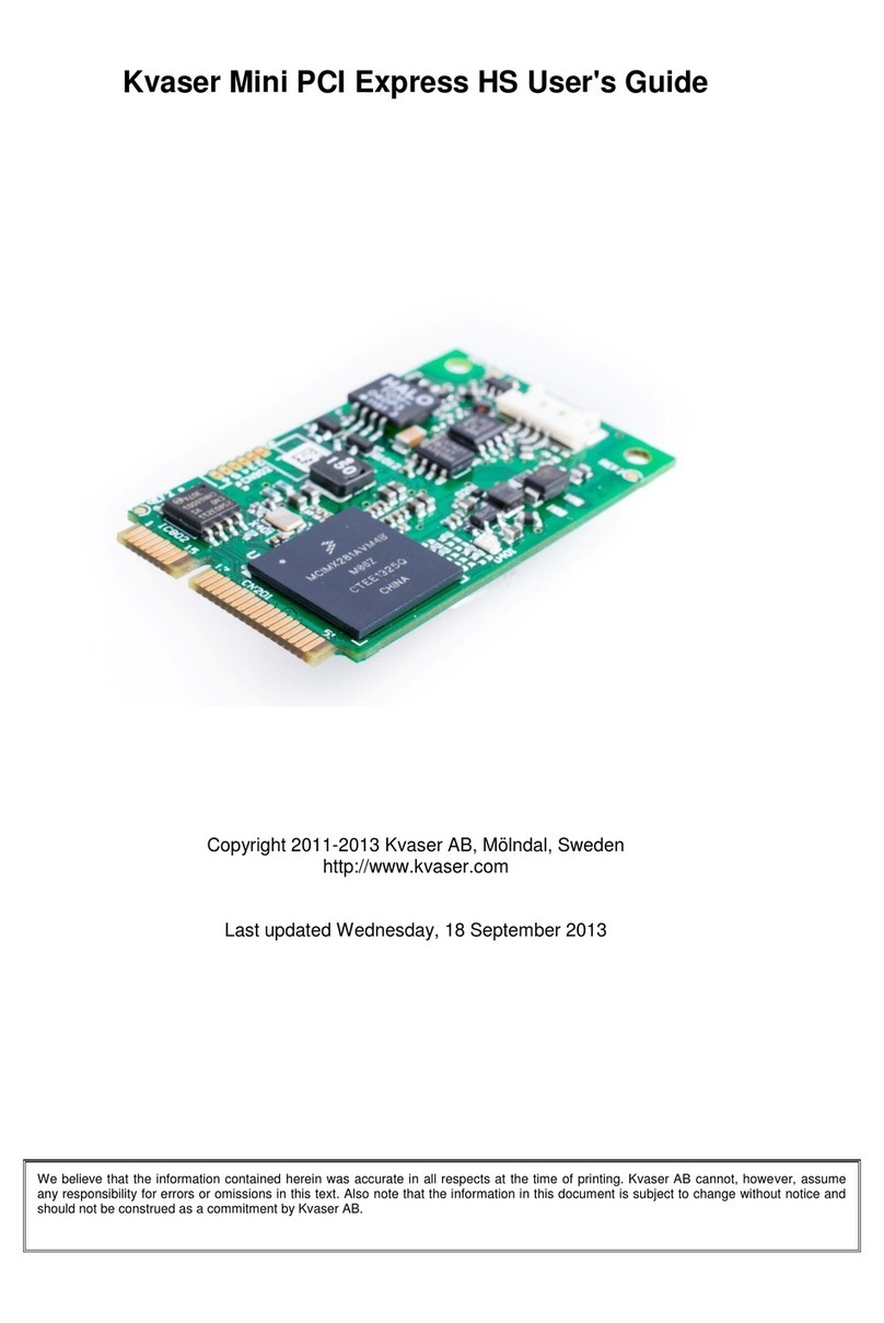
SimTech SIMCom SIM521 Series User manual

Development Kit Manual
SIM521x_EVB_User Guide_V1.01

Document Title: SIM521x EVB User Guide
Version: 1.01
Date: 2011-04-11
Status: Release
Document Control ID: SIM521x_EVB_User Guide_V1.01
General Notes
SIMCom offers this information as a service to its customers, to support application and
engineering efforts that use the products designed by SIMCom. The information provided is
based upon requirements specifically provided to SIMCom by the customers. SIMCom has
not undertaken any independent search for additional relevant information, including any
information that may be in the customer’s possession. Furthermore, system validation of this
product designed by SIMCom within a larger electronic system remains the responsibility of
the customer or the customer’s system integrator. All specifications supplied herein are
subject to change.
Copyright
This document contains proprietary technical information which is the property of SIMCom
Limited., copying of this document and giving it to others and the using or communication of
the contents thereof, are forbidden without express authority. Offenders are liable to the
payment of damages. All rights reserved in the event of grant of a patent or the registration of
a utility model or design. All specification supplied herein are subject to change without
notice at any time.
Copyright © Shanghai SIMCom Wireless Solutions Ltd. 2011

Smart Machine Smart Decision
SIM521x EVB User Guide 11.04.2011
2
Contents
Contents ............................................................................................................................................2
Figure Index ......................................................................................................................................3
Table Index........................................................................................................................................3
Version History .................................................................................................................................4
1 Overview........................................................................................................................................5
2 SIM521x EVB ...............................................................................................................................6
3 EVB accessories.............................................................................................................................8
4 Accessory Interface ........................................................................................................................9
4.1 Power Interface ....................................................................................................................9
4.2 Audio Interface...................................................................................................................10
4.3 SIM card interface..............................................................................................................11
4.4 SD card interface................................................................................................................12
4.5 RS232 Interface..................................................................................................................13
4.6 Operating Status LED ........................................................................................................14
4.7 Camera interface ................................................................................................................15
4.8 USB interface.....................................................................................................................19
4.9 Switch interface..................................................................................................................19
4.10 IIC expand IO interface....................................................................................................20
4.11 Audio & GPIO interface...................................................................................................21
5 EVB and accessories....................................................................................................................22
6 Quickly start.................................................................................................................................23
6.1 Running..............................................................................................................................23
6.2 Installing Driver .................................................................................................................23
6.3 Connecting Net and calling ................................................................................................24
6.4 Downloading......................................................................................................................24
6.5 Turning off .........................................................................................................................25
6.6 Measuring the current consumption...................................................................................25

Smart Machine Smart Decision
SIM521x EVB User Guide 11.04.2011
3
Figure Index
FIGURE 1: EVB VIEW ...........................................................................................................................6
FIGURE 2: EVB ACCESSORY...............................................................................................................8
FIGURE 3: POWER SELECTION JUMPER ....................................................................................9
FIGURE 4: AUDIO INTERFACE .........................................................................................................10
FIGURE 5: SIM CARD SOCKET......................................................................................................... 11
FIGURE 6: SD CARD SOCKET...........................................................................................................12
FIGURE 7: SERIAL PORT....................................................................................................................13
FIGURE 8: STATUS LED .....................................................................................................................14
FIGURE 9: CAMERA INTERFACE .....................................................................................................15
FIGURE 10: USB INTERFACE ............................................................................................................19
FIGURE 11: SWITCH INTERFACE.....................................................................................................19
FIGURE 12: IO INTERFACE................................................................................................................20
FIGURE 13: AUDIO AND GPIO INTERFACE....................................................................................21
FIGURE 14: EVB AND ACCESSORIES..............................................................................................22
FIGURE 15: USB INTERFACE UPDATE PROCEDURE ...................................................................25
FIGURE 16: CURRENT CONSUMPTION IN THE SLEEP MODE ...................................................26
Table Index
TABLE 1:SIM521X EVB KEY FEATURES...........................................................................................5
TABLE 2: POWER SUPPLY ...................................................................................................................9
TABLE 3: HEADSET INTERFACE......................................................................................................10
TABLE 4: EARPHONE INTERFACE...................................................................................................10
TABLE 5: SIM CARD SOCKET........................................................................................................... 11
TABLE 6: SD CARD SOCKET.............................................................................................................12
TABLE 7: SERIAL INTERFACE ..........................................................................................................13
TABLE 8: NETWORK STATUS LED ..................................................................................................14
TABLE 9: POWER INDICATOR LEDS ...............................................................................................14
TABLE 10: CAMERA SIGNALS (J206 SOCKET) ..............................................................................15
TABLE 11: CAMERA SIGNALS (J203 SOCKET) ..............................................................................16
TABLE 12: CAMERA SIGNALS (J205 SOCKET) ..............................................................................17
TABLE 13: CAMERA SIGNALS (J208 SOCKET) ..............................................................................18
TABLE 14: USB INTERFACE ..............................................................................................................19
TABLE 15: SWITCH INTERFACE.......................................................................................................19
TABLE 16: IIC EXPAND IO .................................................................................................................20
TABLE 17: AUDIO & GPIO INTERFACE--- J311& J313 PIN LIST ..................................................21

Smart Machine Smart Decision
SIM521x EVB User Guide 11.04.2011
4
Version History
Data Version Description of change Author
2011-04-11 1.01 Origin 3G Team

Smart Machine Smart Decision
SIM521x EVB User Guide 11.04.2011
5
1 Overview
This document gives the usage of SIM521x EVB, user can get useful information about the
SIM521x EVB quickly through this document.
The Debug board is designed for customer to design their own applications by using the 3G
module SIM521x easily.
All the functions of the SIM521x can be used by this board. One can use UART, USB interface to
communicate with the SIM521x, and can design their camera phone by SIM521x. There is one
UART interface, one USB 2.0 interface, one SIM card interface, one T-FLASH card interface,
three camera interfaces, and four audio interfaces on the board and expand I/O interfaces.
One can connect the UART and/or the USB interface to a computer directly.
NOTE: This document is subject to change without notice at any time.
Table 1:SIM521x EVB Key features
Feature Implementation
Power supply 1: DC 6.0V~9.0V
2: USB 5.0V power supply
functions UART interface
USB2.0 interface
SIMCARD interface
TFLASH interface
Four sensor interface
I2C interface
Audio interface
ADC interface
Onkey/Resetkey/Intkey
RF Control switch
UART Control switch
Expanded I/O interface

Smart Machine Smart Decision
SIM521x EVB User Guide 11.04.2011
6
2 SIM521X EVB
Figure 1: EVB view

Smart Machine Smart Decision
SIM521x EVB User Guide 11.04.2011
7
A: SIM521x module interface
B: Headset interface
C: USB interface
D: GPIO led
E: RF control switch (Before the SIM521x is powered on, please make sure that RF control
switch is ON)
F: Serial port shutdown switch (If one wants to use UART, please switch it to ON at first.)
G: Camera interface
H: I2C expand IO interface
I: Audio & GPIO test interface
J: Power on/off of SIM521x
K: RESET key
L: GPIO0 key
M: LDO MIC29302
N: Power select jumper
O: SIM card interface
P: SD card interface
Q: DC power in
R: Handset interface
S: UART interface for AT command transmitting, data exchanging
All hardware interfaces that connect SIM521x to the customers’ cellular application platform are
through a 70-pin 0.5mm pitch board-to-board connector. Sub-interfaces included in this
board-to-board connector are described in detail in following chapters.

Smart Machine Smart Decision
SIM521x EVB User Guide 11.04.2011
8
3 EVB accessories
Figure 2: EVB accessory
A: 6V DC source adapter
B: Antenna transmit line
C: Antenna
D: Headset
E: Serial port line

Smart Machine Smart Decision
SIM521x EVB User Guide 11.04.2011
9
4 Accessory Interface
4.1 Power Interface
Figure 3: Power selection jumper
Table 2: Power supply
Signal Input/Output Description
Adapter_VBAT O 3.8V/2A DC source input
USB_VBAT O 3.8V/0.5A DC source input
VBAT I DC source input
If user wants to use DC adapter as power supply, Adapter_VBAT should be connected to VBAT
on J304 through a jumper as following figure shows.
This board could be powered by USB bus. User should connect the USB pin. USB_VBAT is the
USB power out. If user wants to use USB VBUS to power up the module, please connect
connector VBAT with connector USB_VBAT as following figure shows.and disconnect
Adapter_VBAT.

Smart Machine Smart Decision
SIM521x EVB User Guide 11.04.2011
10
4.2 Audio Interface
Figure 4: Audio Interface
J204 is the headset interface. J201 is the handset interface.
NOTE: The MIC’s polarity must be correct.
Table 3: Headset interface
Pin Signal I/O Description
1 GND Ground
2 HEADSET_MIC+ I Headset microphone input
3 HPH_L O Positive microphone output
4 HPH_R O Negative microphone output
Table 4: Earphone interface
Pin Signal Input/Output Description
5 MIC1P I Positive microphone input
6 EAR1Q_P O Positive receiver output
7 EAR1Q_N O Negative receiver output
8 MIC1N I Negative microphone input
Speaker interface:
Please refer Figure 1. Pin 1 and Pin 2 is the SPK_P and SPK_N on J313.
NOTE: Audio cable must be away from the RF antenna, otherwise TDD noise may be occurred.

Smart Machine Smart Decision
SIM521x EVB User Guide 11.04.2011
11
4.3 SIM card interface
Figure 5: SIM card socket
Table 5: SIM card socket
Pin Signal Input/Output Description
1
V_USIM O
USIM Card Power output automatic
output on USIM mode,one is
3.0V±10%, another is 1.8V±10%.
Current is about 10mA.
2 USIM_RESET O USIM Card Reset
3 USIM_CLK O USIM Card Clock
4 GND Ground
5 SIM_VPP O V_USIM
6 USIM_DATA I/O USIM Card data I/O

Smart Machine Smart Decision
SIM521x EVB User Guide 11.04.2011
12
4.4 SD card interface
Figure 6: SD card socket
J105 is the SD card interface.
Table 6: SD card socket
Pin Signal Input/Output Description
1 SD-DATA2 I/O Data line 2
2 SD-DATA3 I/O Data line 3
3 SD-CMD O Command line
4 SD-VDD O VDD
5 SD-CLK O Clock line
6 GND Ground
7 SD-DATA0 I/O Data line 0
8 SD-DATA1 I/O Data line 1

Smart Machine Smart Decision
SIM521x EVB User Guide 11.04.2011
13
4.5 RS232 Interface
Figure 7: Serial Port
J306 is 9 pins standard RS232 UART interface. It can be connected to a PC directly.
Table 7: Serial Interface
Pin Signal I/O Description
1 DCD O Data carrier detection
2 TXD O Transmit data
3 RXD I Receive data
4 DTR I Data Terminal Ready
5 GND Ground
6 NC NC
7 RTS I Request to Send
8 CTS O Clear to Send
9 RI O Ring Indicator

Smart Machine Smart Decision
SIM521x EVB User Guide 11.04.2011
14
4.6 Operating Status LED
Figure 8: Status LED
Table 8: Network status LED
D301 Status Module Status
Off Module is not running
On Module is running, or voice call is connected
800ms On/ Off Module find the network and registered
200ms On/ Off Data communication
Table 9: Power indicator LEDs
LED I/O Description
GPIO3 (D101) O ADAPTER power indicator
GPIO5 (D103) O USB power indicator

Smart Machine Smart Decision
SIM521x EVB User Guide 11.04.2011
15
4.7 Camera interface
Figure 9: Camera Interface
Camera interface A:
J206 socket has 24 Pin, this 24PIN B to B socket is used to connect a RGB sensor, the socket is
made by HRS(Part number on SIM521x_EVB:DF 30FC-24DS-0.4V).
Table 10: Camera signals (J206 socket)
Pin Signal I/O Description
1 NC NC
2 GND Ground/DGND
3 I2C _SDA I/O IIC data line
4 VDD2.5V
VDD/ AVDD
5 I2C _SCL I IIC clock line
6 CAMIF_RESET O Reset signal
7 CAMIF_VSYNC O Vertical synchronize
8 CAMIF_STDBY O Standby signal
9 CAMIF_HSYNC O Horizon synchronize
10 VDD1.3V VDD/DVDD
11 VDD2.8V VDD/ IOVDD
12 CAMIF_D9 I/O Camera data line 9
13 CAMIF_CLK O Main clock
14 CAMIF_D8 I/O Camera data line 8
15 GND Ground
16 CAMIF_D7 I/O Camera data line 7
17 CAMIF_PCLK I Pixel clock
18 CAMIF_D6 I/O Camera data line 6
19 CAMIF_D2 I/O Camera data line 2
20 CAMIF_D5 I/O Camera data line 5
21 CAMIF_D3 I/O Camera data line 3
22 CAMIF_D4 I/O Camera data line 4
23 Reserved Reserved
24 Reserved Reserved

Smart Machine Smart Decision
SIM521x EVB User Guide 11.04.2011
16
Camera interface B:
J203 socket has 24 Pins. This 24pin B to B connector is produced by NAIS. The PART NO is
AXK724147G.
Table 11: Camera signals (J203 socket)
Pin Signal I/O Description
1 NC
2 GND Ground/DGND
3 I2C _SDA I/O IIC data line
4 VDD3V VDD/ AVDD
5 I2C _SCL I IIC clock line
6 CAMIF_RESET O Reset signal
7 CAMIF_VSYNC O Vertical synchronize
8 CAMIF_STDBY O Standby signal
9 CAMIF_HSYNC O Horizon synchronize
10 VDD1.8V VDD/DVDD
11 VDD2.5V VDD/ IOVDD
12 CAMIF_D9 I/O Camera data line 9
13 CAMIF_CLK O Main clock
14 CAMIF_D8 I/O Camera data line 8
15 GND Ground
16 CAMIF_D7 I/O Camera data line 7
17 CAMIF_PCLK I Pixel clock
18 CAMIF_D6 I/O Camera data line 6
19 CAMIF_D2 I/O Camera data line 2
20 CAMIF_D5 I/O Camera data line 5
21 CAMIF_D3 I/O Camera data line 3
22 CAMIF_D4 I/O Camera data line 4
23 Reserved Reserved
24 Reserved Reserved

Smart Machine Smart Decision
SIM521x EVB User Guide 11.04.2011
17
Camera interface C:
J205 socket has 24 Pin, this 24PIN B to B socket is used to connect a YUV sensor, and the socket
is made by HRS(Part number on SIM521x_EVB:DF 30FC-24DS-0.4V). This is designed to
connect a sensor with 0.3M resolution for our platform using the high 8 data lines for 0.3M sensor
only.
Table 12: Camera signals (J205 socket)
Pin Signal I/O Description
1 NC
2 GND Ground
3 I2C _SDA I/O IIC data line
4 VDD3V VDD/AVDD
5 I2C _SCL I IIC clock line
6 CAMIF_RESET O Reset signal
7 CAMIF_VSYNC O Vertical synchronize
8 CAMIF_STDBY O Standby signal
9 CAMIF_HSYNC O Horizon synchronize
10 VDD1.8V VDD/DVDD
11 VDD2.5V VDD/IOVDD
12 NC
13 CAMIF_CLK O Main clock
14 NC
15 GND Ground/AGND
16 CAMIF_D9 I/O Camera data line 9
17 CAMIF_PCLK I Pixel clock
18 CAMIF_D8 I/O Camera data line 8
19 CAMIF_D4 I/O Camera data line 4
20 CAMIF_D7 I/O Camera data line 7
21 CAMIF_D5 I/O Camera data line 5
22 CAMIF_D6 I/O Camera data line 6
23 CAMIF_D3 I/O Camera data line 3
24 CAMIF_D2 I/O Camera data line 2

Smart Machine Smart Decision
SIM521x EVB User Guide 11.04.2011
18
Camera interface D:
J208 socket has 24 Pins. This 24pin B to B connector is produced by NAIS. The PART NO is
AXK824145WG. This is designed to connect a sensor with 0.3M resolution for our platform using
the high 8 data lines for 0.3M sensor only.
Table 13: Camera signals (J208 socket)
Pin Signal I/O Description
1 NC
2 GND Ground
3 I2C _SDA I/O IIC data line
4 VDD2.5V
VDD/AVDD
5 I2C _SCL I IIC clock line
6 CAMIF_RESET O Reset signal
7 CAMIF_VSYNC O Vertical synchronize
8 CAMIF_STDBY O Standby signal
9 CAMIF_HSYNC O Horizon synchronize
10 NC VDD/DVDD
11 VDD1.8V VDD/IOVDD
12 CAMIF_D9 I/O Camera data line 9
13 CAMIF_CLK O Main clock
14 CAMIF_D8 I/O Camera data line 8
15 GND Ground/AGND
16 CAMIF_D7 I/O Camera data line 7
17 CAMIF_PCLK I Pixel clock
18 CAMIF_D6 I/O Camera data line 6
19 CAMIF_D2 I/O Camera data line 2
20 CAMIF_D5 I/O Camera data line 5
21 CAMIF_D3 I/O Camera data line 3
22 CAMIF_D4 I/O Camera data line 4
23 Reserved Reserved
24 Reserved Reserved

Smart Machine Smart Decision
SIM521x EVB User Guide 11.04.2011
19
4.8 USB interface
Figure 10: USB Interface
It is a normal 4Pin USB connector.
Table 14: USB interface
Pin Signal I/O Description
1 USB_VBUS I 5V
2 USB_DM I/O D+ line
3 USB_ DP I/O D- line
4 GND Ground
4.9 Switch interface
Figure 11: Switch Interface
Table 15: Switch interface
Pin Signal I/O Description
1 GPIO4 I RF switch:ON : Normal mode
OFF : Flight mode
2 RS232 chip SHUTDOWN I UART switch
3 PWRER_ON I Power on the module
4 RESET I Reset the module
5 GPIO0 I A key for interrupt
Table of contents
Popular Microcontroller manuals by other brands
Division 6
Division 6 CEM3340 VCO Build instructions
Nuvoton
Nuvoton NuMicro M2351 Series quick start guide
Cypress
Cypress CY3642 quick start guide
Texas Instruments
Texas Instruments CC2530 ZigBee Development Kit user guide
Texas Instruments
Texas Instruments CC1110 user guide
Renesas
Renesas V850E2/Fx4 user manual


