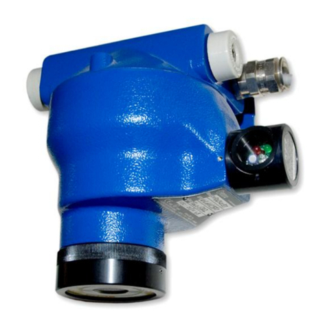
Simtronics GD1 MK3 User manual

P/N: 850-816926-EN Rev6
Operating Manual
Simtronics GD1 MK3
Toxic Open Path Gas Detector

GD1 Page 2 of 76 850-816926-EN R06
Copyright June 2018 by Simtronics A.S.
All rights reserved. No reproduction of all or part of this document, in any form, is permitted
without the written consent of Simtronics A.S.
All of the information that is provided in this document is accurate to the best of our
knowledge.
As a result of continuous research and development, the specifications of this product may
be changed without prior notice.
Simtronics A.S.
Kabelgaten 8, Økern Næringspark
PO Box 314, Økern, NO-0511 Oslo, Norway
https://gasdetection.3M.com

GD1 Page 3 of 76 850-816926-EN R06
Thank you for choosing this SIMTRONICS instrument.
All of the necessary actions have been taken in order to ensure your complete satisfaction
with this equipment.
It is important that you read this entire manual carefully and thoroughly.
Limitation of Liability
The Company SIMTRONICS A.S., hereinafter referred to as “SIMTRONICS” throughout
this document, shall not be held responsible for any damage to the equipment or for
any physical injury or death resulting in whole or in part from the inappropriate use or
installation of the equipment, non-compliance with any and all instructions, warnings,
standards and/or regulations in force.
No business, person or legal entity may assume responsibility on behalf of
SIMTRONICS, even though they may be involved in the sale of SIMTRONICS products.
SIMTRONICS shall not be responsible for any direct or indirect damage, or any direct or
indirect consequence, resulting from the sale and use of any of its products UNLESS
SUCH PRODUCTS HAVE BEEN SELECTED BY SIMTRONICS ACCORDING TO THE
APPLICATION.
Ownership clauses
The drawings, specifications, and information herein contain confidential information
that is the property of SIMTRONICS.
This information shall not, either in whole or in part, by physical, electronic, or any
other means whatsoever, be reproduced, copied, divulged, translated, or used as the
basis for the manufacture or sale of SIMTRONICS equipment, or for any other reason
without the prior consent of SIMTRONICS.
Warning
This is not a contractual document. In the best interest of its customers and with the
aim of improving performance, SIMTRONICS reserves the right to alter the technical
features of its equipment without prior notice.
READ THESE INSTRUCTIONS CAREFULLY BEFORE THE FIRST USAGE: these instructions
should be read by all persons who have or will have responsibility for the use,
maintenance, or repair of the instrument.
This instrument shall only be deemed to be in conformance with the published
performance if used, maintained, and repaired in accordance with the instructions of
SIMTRONICS by SIMTRONICS personnel or by personnel authorized by SIMTRONICS.

GD1 Page 4 of 76 850-816926-EN R06
Important Information
The modification of the material and the use of parts of an unspecified origin shall
entail the cancellation of any form of warranty.
The use of the unit has been projected for the applications specified in the technical
characteristics. Exceeding the indicated values cannot in any case be authorized.
SIMTRONICS recommends regular testing of fixed gas detection installations (read
Chapter 6).
Warranty
The GD1 comes with a 5 year limited warranty on the product. The warranty covers
correct function inside specified tolerances. Warranty is void if the detector has been
installed or operated in conflict with specifications and procedures given in this
operating manual.
Destruction of the equipment
European Union (and EEA) only. This symbol indicates that, in conformity with
directive DEEE (2002/96/CE) and according to local regulations, this product may
not be discarded together with household waste.
It must be disposed of in a collection area that is set aside for this purpose, for
example at a site that is officially designated for the recycling of electrical and
electronic equipment (EEE) or a point of exchange for authorized products in the event of
the acquisition of a new product of the same type as before.

GD1 Page 5 of 76 850-816926-EN R06
TABLE OF CONTENTS
1. Introduction...................................................................................................................7
1.1. The system ........................................................................................................7
1.2. Definitions .........................................................................................................7
2. Installation .....................................................................................................................9
2.1. System parts......................................................................................................9
2.2. Positioning.......................................................................................................10
2.3. Mounting.........................................................................................................10
2.3.1. Mounting on pole.........................................................................................11
2.4. Sun shielding ...................................................................................................11
2.5. Electrical connection and wiring......................................................................12
2.5.1. Alternative wiring configurations .................................................................15
2.5.2. Cable types and specification .......................................................................16
2.5.3. Earth connection ..........................................................................................16
2.5.4. Performing loop test ....................................................................................17
3. Commissioning.............................................................................................................21
3.1. Preparation......................................................................................................21
3.2. Coarse alignment.............................................................................................21
3.3. Fine tuning.......................................................................................................23
3.3.1. Using a Web browser for tuning of signal strength......................................23
3.3.2. Using a HART® for tuning of signal strength.................................................30
3.4. Function test....................................................................................................35
3.4.1. Performing function test with CO2as a non-toxic alternative......................36
4. Operation.....................................................................................................................39
4.1. Analogue Output Protocol...............................................................................39
4.2. Test Cell filling and emptying instructions.......................................................40
5. Maintenance................................................................................................................41
5.1. Regular maintenance.......................................................................................41
5.2. Cleaning of optical surfaces.............................................................................41
6. Troubleshooting...........................................................................................................43
6.1. Error codes ......................................................................................................45
6.2. Tuning detector for less noise .........................................................................46
6.3. Interference from another GD1 ......................................................................48
6.4. Download the Diagnostics file .........................................................................48
6.5. Uploading a Configuration file.........................................................................49

GD1 Page 6 of 76 850-816926-EN R06
7. Certifications and standards ....................................................................................... 53
7.1. Certification .................................................................................................... 53
7.2. Marking........................................................................................................... 53
7.3. Specific condition for use in Explosive Atmosphere “X” ................................. 53
8. Accessories and spare parts ........................................................................................ 55
8.1. Ordering information for the GD1 .................................................................. 57
9. Technical Specifications .............................................................................................. 59
10. System description...................................................................................................... 61
10.1. System ............................................................................................................ 61
10.2. Application areas ............................................................................................ 62
10.3. Positioning considerations.............................................................................. 63
10.3.1. General positioning considerations regarding a gas cloud ..................... 63
10.4. Detection principles........................................................................................ 64
10.5. How to connect to the web interface with the Ethernet cable ...................... 65
10.6. Data logging functionality ............................................................................... 67
11. Support and contact details ........................................................................................ 71
11.1. Shipping instruction sending units to support ................................................ 71
EU Declaration of conformity............................................................................................... 75

GD1 Page 7 of 76 850-816926-EN R06
1. INTRODUCTION
1.1. The system
The GD1 is a laser-based open path Gas Detector with a separate transmitter (TX) and
receiver (RX). The TX emits infrared laser light detected by the RX. The detection principle
is based on measuring the absorption of light by the gas molecules along the optical line-
of-sight.
RECEIVER TRANSMITTER
1.2. Definitions
TX
Transmitter
RX
Receiver
Absolute
transmission
Strength of the optical signal
Relative
transmission
The relative strength of the optical signal in percentage relative to the
Absolute transmission when finishing alignment.
During commissioning, the GD1 is set up with optimum alignment and
signal strength. The relative transmission is used to keep track on how dirty
or out of alignment the system has become after the GD1 was
commissioned.
Laser light

GD1 Page 8 of 76 850-816926-EN R06
THIS PAGE LEFT INTENTIONALLY BLANK

GD1 Page 9 of 76 850-816926-EN R06
2. INSTALLATION
The area in which the detector may be installed must be in accordance
with the certification of the detector and in accordance with the
standards of the appropriate authority in the country of installation.
2.1. System parts
RECEIVER TRANSMITTER
The complete GD1 system consists of a TX sending a laser beam to the RX. Communication
to control room and power to the GD1 is connected to the TX. Between the TX and RX
there is a cable with communication and power.
The TX where the laser is located sends a diffused light beam (invisible) to the receiver. The
beam is shaped as a cone, not a focused laser beam as you might expect from a laser
pointer. The TX comes complete with the TX and junction box mounted on a backing plate.
The RX has a larger optical aperture to collect the transmitted light and add margin to path
alignment. The TX and RX communicate on a data link (cable). The RX comes complete with
the RX and junction box mounted on a backing plate.

GD1 Page 10 of 76 850-816926-EN R06
2.2. Positioning
Deciding on how the GD1 detectors should be placed at the site is discussed in section
10.3. During installation the detector should be positioned according to the following
points:
•Check that there is a free line of sight between the TX and RX.
•The measuring path should be horizontal.
•Avoid that the measuring path is blocked by temporary scaffolding, parked cars,
high traffic and moving structures.
•The detector should be attached to a mechanically rigid structure.
•The GD1 should be positioned as to avoid more than one TX transmitting into a RX.
Failing to do this can lead to interference between the detectors and false alarms.
•The transmitter and receiver units are to be fitted perpendicular to the measuring
path, within ± 20 degrees.
2.3. Mounting
The GD1 Transmitter and Receiver system assemblies are delivered on a 6mm (1/4")
universal mounting plate suitable for most mounting situations. See figure below for
general dimensions (mm).
The transmitter and receiver units are to be mounted perpendicular to the measuring path,
within ± 20 degrees.
397
210
185
9
372

GD1 Page 11 of 76 850-816926-EN R06
2.3.1. Mounting on pole
If the detector is mounted on a pole/pipe, it is important that the pole/pipe is structurally
rigid enough that the detector will not move out of its alignment tolerances. When
choosing pole diameter, one must account for mounting height. Simtronics recommends
that for a mounting height of 2m, minimum Ø 3” (75 mm) pole is used for sufficient rigidity.
If mounting height is increased, pole/pipe diameter should increase accordingly.
2.4. Sun shielding
The transmitter and receiver are fitted with a
sun shield as standard.
In locations where there is a risk that the
temperatures can exceed the certified limits for
the ambient temperature, a canopy can be
mounted above the detector for additional sun
shielding.
It is not recommended to store a GD1 for a long
time un-powered outside in a hot environment.
If the detector is stored unpowered in high
temperatures for several months, it might lead
to settings needing adjustment.

GD1 Page 12 of 76 850-816926-EN R06
2.5. Electrical connection and wiring
Make sure that power is disconnected or switched off before connecting any wires.
The system supplying power to the GD1 shall have a fuse allowing maximum 1 A of
current to enter the GD1.
The detector must be earthed for electrical safety and to limit the effects of radio
frequency interference. Earth connection points are provided on the underside of the
GD1 housing and inside the Junction Box.
The connection terminals are accessed by removing the covers of the junction boxes.
Wiring diagrams are shown below. The system cable only goes to the transmitter unit. The
cable between the junction boxes carries the power to the receiver and the
communication signals. Unless otherwise instructed, please observe that the system power
and analogue output cable is terminated on the transmitter side of the GD1 system.

GD1 Page 13 of 76 850-816926-EN R06
Wiring overview Transmitter Junction Box:
System
cable
Terminal
Cable from GD1
instrument
Wire color
Transmitter Junction Box
Com. cable
+24 VDC
1
White
+24 VDC
+24 VDC
0 V Return
(GND)
2
Brown
0 V Return
0 V Return
(GND)
3
Green
Ethernet®
4
Yellow
Ethernet®
5
Black
Ethernet®
6
Violet
Ethernet®
Signal to
control
room
7
Blue
4-20 mA primary gas value and
HART®.
Default is source configuration
with 4-20 mA measured
between terminals 7 and 2 (0V).
For sink configuration 4-20 mA
is measured between terminals
7 and 1 (24 V).
8
Red
Secondary current loop:
Relative transmission
(configurable).
PE
-
Earth
11*
Gray
TxRx Com 1 from Rx
TxRx Com 1
12*
Pink
TxRx Com 2 from Rx
TxRx Com 2
PE
-
Earth
Note! Instrument damage can occur if incorrectly connected.
* Wires to terminal 11 and 12 shall be twisted.

GD1 Page 14 of 76 850-816926-EN R06
Wiring overview Receiver Junction box:
System
cable
Terminal
Cable from GD1
instrument
Wire color
Receiver Junction Box
Com. cable
1
White
+24 VDC from Tx
+24 VDC
2
Brown
0 V Return from Tx
0 V Return
(GND)
3
Green
Do not connect.
4
Yellow
Do not connect.
5
Black
Do not connect.
6
Violet
Do not connect.
7
Blue
Tertiary current loop: Relative
transmission (configurable).
8
Red
Do not connect.
PE
-
Earth
11*
Gray
TxRx Com 1 from Tx
TxRx Com 1
12*
Pink
TxRx Com 2 from Tx
TxRx Com 2
PE
-
Earth
Note! Instrument damage can occur if incorrectly connected.
* Wires to terminal 11 and 12 shall be twisted.

GD1 Page 15 of 76 850-816926-EN R06
2.5.1. Alternative wiring configurations
The default wiring configuration for the GD1 is with power and 4-20 mA connected to the
TX side, and with power supplied to the RX via the TX junction box.
Wiring alternative 1: System power connected on the receiver side
Wiring alternative 2: Power on both receiver and transmitter side
The instrument 0 V shall be the same for both RX and TX.

GD1 Page 16 of 76 850-816926-EN R06
2.5.2. Cable types and specification
Cables must be chosen in accordance with applicable regulations.
System cable:
Cable from the GD1 system to control system. The table below indicates maximum cable
lengths (2-wire) restrictions due to voltage drop over the power supply cable.
Min. single wire cross area
0.75 mm2
1.25mm2
2.5 mm2
4.0 mm2*
Supply voltage 24 VDC, terminal 1.
Max length.
125 m
250 m
400 m
800 m*
Supply voltage 0 V Return on
terminal 2.
Max length.
Primary Loop, terminal 7.
The wiring should be such that the total
impedance of the current loop, including cabling,
connections and input on control system should be
maximum 500 .
*The GD1 is by default delivered with terminal blocks for wires up to 2.5 mm2.
TX / RX communication cable:
Cable between the GD1 Transmitter and Receiver, containing data and power supply. The
cable shall be an instrument type with 2 twisted, individually shielded pairs and with an
overall shield. Wiring up to 200 meters shall have a minimum cross section of 0.75 mm2.
For longer distances the maximum impedance of 70 must be considered.
2.5.3. Earth connection
The detector housing must be connected to local earth via the external earth point. The
wire should be minimum 4 mm2(8 AWG) and as short as possible.
Earth point

GD1 Page 17 of 76 850-816926-EN R06
The shield of the system cable should be connected to instrument earth in the central
control module, and is normally not terminated at the detector. Exception: If extra RFI
protection is required, and the installations grounding principles/regulations allows it, the
shield is terminated to local ground via the internal earth point at the detector instead.
2.5.4. Performing loop test
After powering up the GD1 a test can be performed of the 4-20 mA wiring. The loop test is
performed by the procedure below.
#
Description
Illustration
1
On the transmitter, connect the Ethernet adapter
to the Junction Box terminals 3 - 6.
Internal earth point

GD1 Page 18 of 76 850-816926-EN R06
2
Use a device having Web browsing capabilities, for
example laptop, to connect with the wireless
router or Ethernet cable. If using the wireless
router, from your device connect to the network
SSID: “GD1”
In the web browser of your device, enter the GD1
Service Interface on the address
http://192.168.1.237
3
Log into the Service Interface with the Operator
password: "gd1tlc"
After logging in as Operator more functions are
accessible as illustrated in the right image.
4
Run loop testing in the Web interface "I/O
verification" screen.
Recommend to use at least 60 sec test time.
Enter forced value. For example 12 mA is 50% of
full scale.

GD1 Page 19 of 76 850-816926-EN R06
5
When clicking “Test” the test value will be forced
on the 4-20 mA Loop1 terminal (terminal 7 in the
GD1 Junction Box).
Verify that the analogue output matches the test
value.

GD1 Page 20 of 76 850-816926-EN R06
THIS PAGE LEFT INTENTIONALLY BLANK
Table of contents
Other Simtronics Gas Detector manuals
