AKO 52201 User manual

E GB F PTD
5220H101 Ed.12
AKO-52201 AKO-52202 AKO-52203
AKO-52204 AKO-52205 AKO-52210
Alarma de detección de gases refrigerantes para conexión permanente
Gas refrigerant detection alarm for permanent connection
Alarme de détection de gaz frigorigène pour connexion permanente
KältemittelGas-Detektionsalarm für dauerhaften Anschluss
Alarme de detecção de gases refrigerantes para conexão permanente

Índice
1.-
2.- Versiones y referencias.....................................................................................................................3
3.- Descripción del equipo.....................................................................................................................4
Central de alarma ..................................................................................................................4
Detector de gas AKO-52211/12/13/14....................................................................................4
Detector de gas AKO-52215...................................................................................................4
4.- Instalación.......................................................................................................................................5
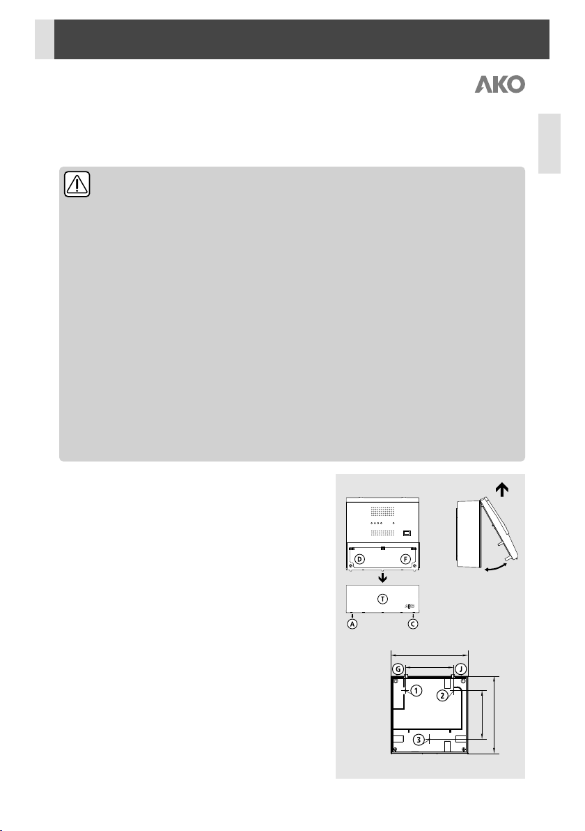
Montaje de la central.............................................................................................................5
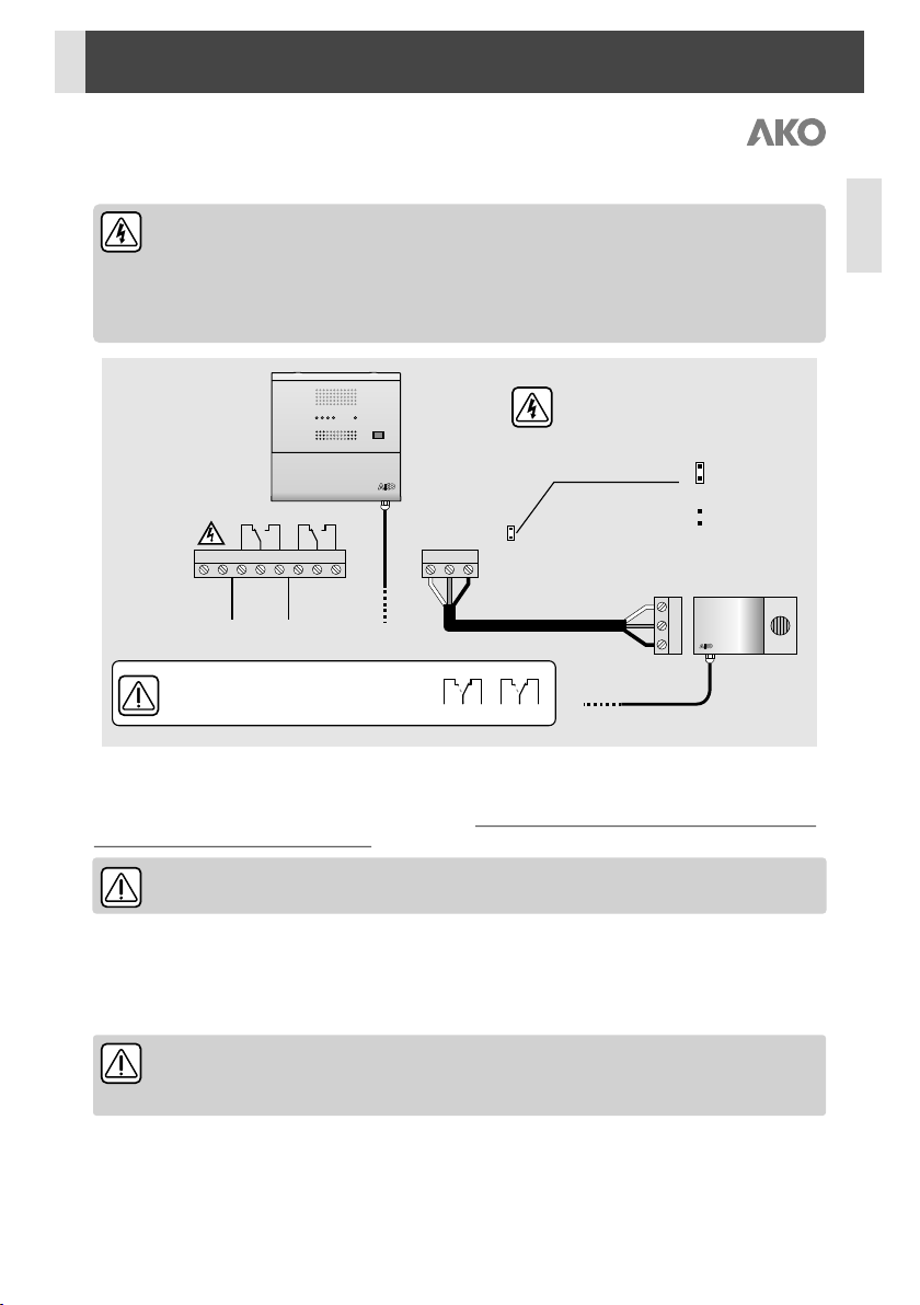
Montaje del detector..............................................................................................................6
Conexionado .........................................................................................................................7
Configuración ........................................................................................................................7
5.- Funcionamiento...............................................................................................................................8
6.- Mantenimiento................................................................................................................................9
7.- Advertencias..................................................................................................................................10
8.- Datos técnicos...............................................................................................................................10
Introducción ....................................................................................................................................3
AKO Electromecànica, le agradece y felicita por la adquisición de nuestro producto, en cuyo desarrollo y fabricación se han utilizado las
tecnologías más innovadoras, así como unos rigurosos procesos de producción y control de calidad.
Nuestro compromiso por conseguir la satisfacción de nuestros clientes y el continuo esfuerzo por mejorar día a día lo constatan las diversas
certificaciones de calidad obtenidas.
Este es un producto de altas prestaciones y tecnológicamente avanzado. De su correcta planificación, instalación, configuración y puesta en
marcha, dependerá en gran medida su funcionamiento, así como las prestaciones finales alcanzadas. Lea detenidamente este manual antes
de proceder a instalarlo, y respete en todo momento las indicaciones del mismo.
Únicamente personal cualificado puede instalar o realizar la asistencia técnica del producto.
Este producto ha sido desarrollado para su utilización en las aplicaciones descritas en su manual, AKO Electromecànica no garantiza su
funcionamiento en cualquier utilización no prevista en dicho documento, así como no se responsabilizará en ningún caso de los daños de
cualquier tipo que pudiera ocasionar una utilización, configuración, instalación o puesta en marcha incorrectas.
Es responsabilidad del instalador y del cliente el cumplir y hacer cumplir las normativas aplicables a las instalaciones donde se destinarán
nuestros productos. AKO Electromecànica no se responsabilizará de los daños que puedan ocasionar el incumplimiento de las mismas. Siga
rigurosamente las indicaciones descritas en este manual.
Siempre que un malfuncionamiento del equipo pueda producir daños personales o materiales, es responsabilidad del instalador y del
personal de mantenimiento, aplicar las medidas preventivas y de protección necesarias para evitarlos. Del mismo modo, debe revisarse el
correcto funcionamiento del equipo periódicamente.
De cara a alargar el máximo posible la vida de nuestros equipos, se deben cumplir las siguientes observaciones:
No exponga los equipos electrónicos al polvo, suciedad, agua, lluvia, humedad, temperaturas elevadas, agentes químicos, o
sustancias corrosivas de cualquier tipo.
No someta los equipos a golpes o vibraciones ni intente manipularlos de forma diferente a la indicada en el manual.
No supere en ningún caso las especificaciones y limitaciones indicadas en el manual.
Respete en todo momento las condiciones ambientales de trabajo y almacenaje indicadas.
Durante la instalación y al finalizarla, evite dejar cables sueltos, rotos, desprotegidos o en malas condiciones, pueden suponer
un riesgo para el equipo y para sus usuarios.
AKO Electromecànica se reserva el derecho a cualquier modificación tanto en la documentación como en el producto sin previo aviso.
Pág.
2

Español
1.- Introducción
Alarma de detección de fugas de gas refrigerante para ser utilizada en instalaciones frigoríficas, diseñada para dar
cumplimiento a la norma EN 378-3.
2.- Versiones y referencias
* Los niveles de pre-alarma y alarma pueden diferir levemente de lo mostrado en la tabla en
función del tipo de gas detectado.
**AKO asegura la activación de la alarma a partir de una concentración de gas refrigerante de
7000 ppm. En función del tipo de gas utilizado, la alarma puede activarse a concentraciones
inferiores.
MODELO
DESCRIPCIÓN
DETECTOR INCLUIDO
ALIMENTACIÓN
AKO-52201
Central de alarma + Detector
AKO-52211
90-260V~
50/60 Hz
AKO-52202
Central de alarma + Detector
AKO-52212
AKO-52203
Central de alarma + Detector
AKO-52213
AKO-52204
Central de alarma + Detector
AKO-52214
AKO-52205
Central de alarma + Detector
AKO-52215
AKO-52210
Central de alarma
-
AKO-52211
Detector para freones tipo A
-
-
AKO-52212
Detector para freones tipo B
AKO-52213
Detector para amoniaco (NH )
3
AKO-52214
Detector para freones tipo U
AKO-52215
Detector para CO (R-744)
2
AKO-5220x
AKO-52210
AKO-5221x
DETECTOR
GASES QUE DETECTA
PRE-ALARMA
ALARMA
AKO-52211
R-134a, R-407C, R-410A, R-409A, R-407F
500 ppm*
1000 ppm*
AKO-52212
R-404A, R-507A, R-22, R-408A
AKO-52213
R-717 (NH / amoniaco)
3
250 ppm
500 ppm
AKO-52214
R-134a, R-407C, R-410A, R-409A, R-404A, R-22, R-422A
R-422D, R-408A, R-507A, R-407F, R-407A
3500 ppm**
7000 ppm**
AKO-52215
R-744 (CO )
2
3000 ppm
8000 ppm
3

3.- Descripción del equipo
Central de alarma
Pulsador de mute/reset
Silencia alarma o borra alarmas guardadas
Jumper de pre-alarma
Permite activar la detección de pre-alarma.
Antes de utilizar esta opción, asegurese de que la
normativa le permite dos niveles de alarma.
En caso de utilizar el detector de amoniaco (AKO-52213) o de CO (AKO-52215), la pre-
2
alarma debe estar habilitada.
Detector de gas AKO-52211/12/13/14
Selector de retardo
Retarda la activación de alarmas detectadas en la central.
Los indicadores de estado del detector indicarán las
alarmas y pre-alarmas de forma inmediata, sin tener en
cuenta los retardos.
IMPORTANTE: La configuración del retardo debe hacerse con la alimentación de la central desconec-
tada, de lo contrario no tendrán efecto.
Detector de gas AKO-52215
Selector de respuesta
Define el tipo de respuesta del detector y afecta tanto a
la lectura mostrada en el indicador, como a la activación
de las alarmas.
El intervalo entre una lecturas es de 15 segundos, independientemente de la posición del selector.
ALARMA VISUAL
ALARMA ACÚSTICA
JUMPER PRE-ALARMA
PULSADOR DE
MUTE/RESET
ESTADO DETECTOR
ESTADO ALIMENTACIÓN
Pre-alarma deshabilitada
Pre-alarma habilitada
Respuesta inmediata: El detector reacciona en
función de la última lectura obtenida.*
Respuesta retardada: El detector reacciona
según el valor promedio de las últimas 11
lecturas.
1 2 5 8
INDICADORES DE ESTADO
SELECTOR DE
RESPUESTA
INDICADOR DE CONCENTRACIÓN DE CO2
EN PARTES POR MILLÓN (ppm)
*Valor por defecto.
* Valor por defecto
Sin retardo* 30 seg.
60 seg. 120 seg.
INDICADORES DE ESTADO
SELECTOR DE RETARDO
4
ON
ON ON
ON
ON
ON
ON
ON
ONON

FIG. 2
FIG. 1
222,1 mm
140 mm
222,1 mm
140 mm
FIG. 3
4.- Instalación
El cableado entre el detector y la central NUNCA debe instalarse en una conducción junto con cables de potencia,
control o alimentación.
ADVERTENCIAS
-Los sensores supervisan un punto y no un área. Si la fuga de gas no alcanza el sensor, o el
nivel de concentración en dicho punto no alcanza los valores previstos según el tipo de
gas (ver pág. 3) no se activará ninguna alarma.
-La alarma y los detectores deben ser instalados en un sitio protegido de las vibraciones, del agua y de los
gases corrosivos, donde la temperatura ambiente no supere el valor reflejado en los datos técnicos. La central
debe situarse en algún lugar donde se garantice la presencia habitual de personas que puedan alertar de la
presencia de alarmas.
-Tanto la alarma como el detector de gas no son adecuados para zonas clasificadas como potencialmente
explosivas.
Condiciones de trabajo:
-Mantener la atmósfera de trabajo del detector libre de agentes químicos (Disolventes, pinturas,
alcoholes, productos de limpieza, siliconas y derivados, etileno, etc.).
-Evitar la manipulación de gases refrigerantes cerca del detector.
-Evitar instalar el detector cerca de productos o equipos que puedan desprender CO .
2
-La respiración humana cerca del detector puede elevar el nivel de CO y generar falsas alarmas.
2
-No pintar el detector ni colocarlo cerca de disolventes o pinturas.
-El detector debe instalarse alejado de:
ŸZonas donde se puedan producir procesos de fermentación o maduración de producto (pan, pizza,
frutas, etc.).
ŸSalidas de humo localizadas o procedentes de motores, generadores o maquinaria motorizada
(carretillas elevadoras, etc.).
ŸZonas con fuerte ventilación o especialmente húmedas.
Montaje de la central
- Retirar la tapa T del equipo (Fig.1)
- Abrir el equipo y separar el frontal de la caja (Fig.2)
- Realizar los taladros para los prensaestopas necesarios para
entrada de los cables guiándose por los centros pretroquelados en
los laterales de la caja.
- Realizar los 3 taladros en la pared siguiendo los agujeros de
fijación 1,2,3. (Fig.3).
- Fijar los prensaestopas en el equipo.
- Insertar y apretar los 3 tornillos+taco a través de la caja, en los 3
taladros de la pared.
- Insertar los cables en los prensaestopas.
- Montar el frontal en la caja (Fig.2).
- Insertar y apretar los tornillos D, F (Fig.1)
- Conectar los cables según el esquema de conexionado, cerrar la
tapa T, insertar y apretar los tornillos A, C (Fig.1)
Español
5

Montaje del detector
El detector debe instalarse en una zona donde pueda concentrarse la mayor cantidad de gas, próximo a
lugares dónde puedan originarse fugas de gas y accesible para trabajos de mantenimiento. Asi mismo,
es recomendable situarlo alejado de zonas de paso o donde pueda recibir impactos fortuitos.
Diferentes tipos de gas pueden tener diferentes densidades, esto implica que las fugas puedan concentrarse en la
parte más baja de la sala o cerca del techo, tenga en cuenta esto al decidir la altura del detector.
Teniendo en cuenta las características del refrigerante empleado, los sensores de los detectores utilizados para
controlar la concentración deberán estar colocados a la altura de las personas, con una distancia libre alrededor
de unos 50 cm.
-Retirar la tapa del detector (Fig.4).
-Realizar el taladro para el prensaestopas incluido, necesario para
entrada de los cables, guiándose por los centros pretroquelados en
la parte inferior de la base.
-Realizar los 3 taladros en la pared siguiendo los taladros de fijación
(Fig.5).
-Fijar el prensaestopa en la base.
-Insertar y apretar los 3 tornillos+taco a través de la base, en los 3
taladros de la pared.
-Insertar los cables en el prensaestopa y conectarlos según el
esquema de conexionado.
-AKO-52211/12/13/14: Ajustar los retardos de alarma/Pre-alarma
mediante el selector de retardo (Ver pág. 4)
-AKO-52215: Ajustar la respuesta del detector mediante el
selector de respuesta (Ver pág. 4).
-Insertar la tapa y presionar ligeramente hasta escuchar “click”.
Taladros de fijación adecuados
para caja de empotrar universal
Presionar ligeramente
FIG. 4
Taladros
de fijación
8 8 8 8
Selector de
respuesta
168
125,535
92
60
41,5
Max. Ø 3,7
AKO-52215
FIG. 5
Taladros
de fijación
Selector de
retardo
168
125,535
92
60
41,5
Max. Ø 3,7
AKO-52211/12/13/14
6

Salida
Alarma
16A 16A
Salida
Pre-alarma
NC NCNO NOC C
-
S
+
1L
45
2N +3 6 S -
+12Vcc
Entrada
90-260 V~
50/60 Hz
GND
Señal
DETECTOR
Jumper de pre-alarma
Desconectar siempre la alimentación antes
de modificar la posición del jumper.
Max. 200 mts.
Pre-alarma
deshabilitada
Pre-alarma
habilitada
Estado de los relés en caso de fallo en
el suministro eléctrico.
16A 16A
1
45
2 3 6
Conexionado
Desconectar siempre la alimentación para realizar el conexionado.
El circuito de alimentación debe estar provisto de un interruptor para su desconexión de mínimo 2 A, 230 V,
situado cerca del aparato. El cable de alimentación será del tipo H05VV-F o H05V-K. La sección a utilizar dependerá
2
de la normativa local vigente, pero nunca deberá ser inferior a 1 mm .
Los cables para el conexionado del contacto del relé, deberán tener la sección adecuada según el equipo a conectar.
AKO recomienda el uso de cable apantallado para el conexionado de los detectores.
Configuración
Jumper de pre-alarma (detectores de gas)
Permite activar la detección de pre-alarma (Ver pág. 4). Antes de utilizar esta opción, asegurese de que la
normativa le permite dos niveles de alarma.
En caso de utilizar el detector de amoniaco (AKO-52213) o de CO (AKO-52215), la pre-
2
alarma debe estar habilitada.
Función de autodiagnóstico
El equipo incorpora un sistema de autodiagnóstico del detector y del cableado entre el detector y la central de
alarma.
En caso de malfuncionamiento, la central alertará haciendo sonar tres tonos seguidos cada 2 minutos, y activando la
alarma visual y el led de estado del detector, mientras que el detector activará alternativamente sus leds de estado.
Tiempo de calentamiento del detector
Tras recibir alimentación eléctrica, el detector de gas precisa de un tiempo de calentamiento de 10
minutos hasta alcanzar su óptimo funcionamiento.
Español
7

5.- Funcionamiento
CENTRAL DE ALARMA
DETECTOR DE GAS
ESTADO
ALARMA
ACÚSTICA
RELÉS
Alarma
Pre-
alarma
Sin alarma
Off
Off
Off
Intermitente
lento
Off
Pre-alarma
retardada
Off
Off
Off
Off
Intermitente
rápido
Pre-alarma
Intermitente
On
Intermitente
Off
Intermitente
rápido
Alarma
retardada
Intermitente
On
Intermitente
Off
On
Alarma
Intermitente
On
Sonido bi-tonal
Off
On
alarma /
pre-alarma
guardada
Off
Inter-
mitente
Off
Intermitente
lento
Off
Fallo detector /
cableado
On
On
3 tonos cortos cada
2 minutos
Intermitente / alternativo
Sin
alimentación
Off
Off
Off
Off
Off
1
45
2 3 6
A
B
C
D
E
F
1
45
2 3 6
1
45
2 3 6
1
45
2 3 6
1
45
2 3 6
1
45
2 3 6
1
45
2 3 6
*
Concentración de GAS (ppm)
t
Nivel de
pre-alarma
Nivel de
alarma
AB B
C C CD DE EF F
** Si durante el tiempo de retardo de una pre-alarma, la concentración de gas aumenta hasta el valor de alarma,
por razones de seguridad, se cancelará el retardo de pre-alarma, activando la señalización en la central.
* Alarma / pre-alarma guardada
Nos permiten comprobar si se ha disparado alguna alarma / pre-alarma durante
nuestra ausencia.
Pulsador de mute / reset
Durante una alarma, silencia la alarma acústica, en reposo (sin alarma), borra las
alarmas guardadas existentes.
-En la alarma AKO-52204, la función de pre-alarma está desactivada de fábrica, para activarlo, consulte
la página 4.
-El detector de CO (AKO-52215) no dispone de retardo de alarma / pre-alarma.
2
**
1
45
2 3 6
8

Español
6.- Mantenimiento
ŸLimpie la superficie del equipo con un paño suave, agua y jabón.
ŸNo utilice detergentes abrasivos, gasolina, alcohol o disolventes, el sensor puede resultar dañado.
ŸAKO garantiza la calibración de los detectores durante los 3 primeros años desde la fecha de
compra (siempre que se cumplan las condiciones de trabajo del detector, ver página 5),
transcurrido este tiempo, se recomienda reemplazar el detector.
ŸSe recomienda cambiar el detector en caso de haber estado expuesto a altas concentraciones de gas.
Según la norma EN-378, debe comprobarse el correcto funcionamiento del detector al
menos una vez al año, consulte si su normativa local vigente le exige intervalos inferiores.
MÉTODO DE COMPROBACIÓN
ŸPreparación:
ŸDesconectar la alimentación del equipo, abrir la tapa del detector.
ŸAKO-52211/12/13/14: Ajustar el selector de retardo a “sin retardo”.
ŸAKO-52215: ajustar el selector de respuesta a “respuesta inmediata”.
ŸCerrar la tapa y volver a conectar la alimentación del equipo.
ŸEsperar el tiempo de calentamiento del detector antes de iniciar la comprobación.
Inicio de la comprobación:
ŸAKO-52211/13/14: Situar un mechero común a unos 5 cm por debajo del detector y liberar gas durante 4
segundos.
ŸAKO-52212: Situar un mechero común a unos 10 cm por debajo del detector y liberar gas durante 2
segundos.
ŸAKO-52215: Teniendo en cuenta que durante la respiración se expiran elevadas concentraciones de CO , se
2
recomienda comprobar el correcto funcionamiento del sensor realizando diversas expiraciones lo más cerca
posible hasta que el sensor alcance los niveles de pre-alarma y alarma pudiendo comprobar la activación de
los respectivos relés.
Comprobar que pasados breves instantes:
CON PRE-ALARMA HABILITADA:
ŸSe activa la pre-alarma. El indicador verde del detector se apaga y el indicador rojo comienza a parpadear.
La central emite un sonido intermitente. El relé de pre-alarma se activa. Posteriormente se activa la alarma,
El indicador rojo del detector se enciende de forma permanente.
CON PRE-ALARMA DESHABILITADA:
ŸSe activa la alarma, El indicador rojo del detector se enciende de forma permanente. La central de alarma
emite un sonido bitonal. El relé de alarma se activa.
Pasados entre 1 y 2 minutos, las alarmas desaparecen. El indicador rojo del detector se apaga y el verde inicia un
parpadeo lento. Los relés de alarma y pre-alarma se desactivan.
-Si la pre-alarma o la alarma no se activan, intentelo de nuevo liberando gas durante mayor tiempo.
-Una exposición demasiado elevada, puede provocar que se reduzca el retardo entre la activación de la pre-
alarma y la alarma, alargar el tiempo de espera para la desactivación de las mismas.
-Recuerde pulsar el botón de reset para borrar el histórico de alarmas (botón verde) después de la
comprobación.
Una vez finalizada la comprobación, recuerde volver ajustar el selector de retardo a su configuración inicial,
desconectando la alimentación antes de manipularlo.
9

7.- Advertencias
ŸLos detectores miden la concentración de gas en un punto, si la fuga de gas no alcanza el detector, la alarma
no se activará.
ŸLos detectores no pueden supervisar áreas, en caso de requerir una supervisión perimetral, se deben instalar
varios detectores rodeando el area a supervisar.
ŸSe recomienda estudiar minuciosamente la ubicación del/los detector/es, teniendo en cuenta las zonas más
sensibles a padecer fugas, el tipo de gas utilizado, el tamaño y forma de la sala, los flujos de aire, los
trabajos de mantenimiento, etc.
ŸLos detectores descritos han sido diseñados para detectar concentraciones de gas capaces de afectar a las
condiciones ambientales de la sala. No se garantiza la detección de pequeñas fugas de refrigerante.
8.- Datos técnicos
AKO-52210
Alimentación ........................................................................................................................90-260 V~ 50/60 Hz
Potencia máxima absorbida .........................................................................................................................10 VA
Nº de entradas ...................................................................................................................................................1
Compatibilidad de entradas.........................................................................................Solo detectores AKO-5221x
Relé alarma / prealarma..........................................................................................SPDT 230 Vac, 16 A, cos j =1
Temperatura ambiente de trabajo.......................................................................................................0 ºC a 50 ºC
Temperatura ambiente de almacenaje.............................................................................................-30 ºC a 70 ºC
Grado de protección .....................................................................................................................................IP 40
Categoría de instalación ..............................................................................................................II s/ EN 61010-1
Grado de polución.......................................................................................................................II s/ EN 61010-1
Aislamiento doble entre alimentación, circuito secundario y salida relé.
Potencia sonora.......................................................................................................................90 dB(A) a 1 metro
Norma EMC ..........................................................................................................................................EN 61000
Detector AKO-5221x
Alimentación..................................................................................................................................15 Vdc ±3 Vdc
Consumo Típico AKO-52211/12/13/14 .............................................................................................75 mA
AKO-52215..............................................................................................................30 mA
Máximo AKO-52211/12/13/14 ...........................................................................................100 mA
AKO-52215..............................................................................................................50 mA
Temperatura ambiente de trabajo ...................................................................................................-20 ºC a 50 ºC
Temperatura ambiente de almacenaje.............................................................................................-20 ºC a 60 ºC
Rango de humedad máxima permitida..................................................................5 - 85 % HR (sin condensación)
Grado de protección .....................................................................................................................................IP 40
Tipo de sensor AKO-52211/12/13/14...................................................Sn02 (Metal Oxide Semiconductor)
AKO-52215 .......................................................NDIR (Non-Dispersive Infrared Technology)
Rango del visualización (AKO-52215).............................................................................................0 - 9999 ppm
Tiempo de vida...............................................................En función de las condiciones de temperatura y humedad
Norma EMC ..........................................................................................................................................EN 61000
10

Español
11

AKO Electromecànica thanks you and congratulates you on the purchase of our product, the development and manufacture of which involved
the most innovative technologies, as well as rigorous production and quality control processes.
Our commitment to achieving customer satisfaction and our continuous efforts to improve day by day are confirmed by the various quality
certificates obtained.
This is a high performance, technologically advanced product. Its operation and the final performance achieved will depend, to a great extent,
on correct planning, installation, configuration and commissioning. Please read this manual carefully before proceeding to install it and
respect the instructions in the manual at all times.
Only qualified personnel may install the product or carry out technical support.
This product has been developed for use in the applications described in the manual. AKO Electromecànica does not guarantee its operation
in any use not foreseen in this document and accepts no liability in the case of damage of any type which may result from incorrect use,
configuration, installation or commissioning.
Complying with and enforcing the regulations applying to installations where our products are destined to be used is the responsibility of the
installer and the customer. AKO Electromecànica accepts no liability for damage which may occur due to failure to comply with these
regulations. Rigorously follow the instructions described in this manual.
Whenever a malfunction of the device can cause personal or material damages, the fitter and maintenance staff are responsible for applying
the necessary preventive and protection measures to prevent them. In the same way, the correct operation of the device must be periodically
checked.
In order to extend the lifetime of our products to the maximum, the following points must be observed:
Do not expose electronic equipment to dust, dirt, water, rain, moisture, high temperatures, chemical agents or corrosive
substances of any type.
Do not subject equipment to knocks or vibrations or attempt to handle them in any way differently to that indicated in the manual.
Do not under any circumstances exceed the specifications and limitations indicated in the manual.
Respect the indicated environmental conditions for operation and storage at all times.
During installation and on completion of this, avoid the presence of loose, broken or unprotected cables or cables in poor
condition. These may constitute a risk for the equipment and its users.
AKO Electromecànica reserves the right to make any modification to the documentation and the product without prior notification.
Index Pag.
1.-
2.- Versions and references .................................................................................................................12
3.- Equipment description ...................................................................................................................13
Alarm station.......................................................................................................................13
Gas detector AKO-52211/12/13/14......................................................................................13
Gas detector AKO-52215 .....................................................................................................13
4.- Installation ....................................................................................................................................14
Station assembly..................................................................................................................14
Detector assembly................................................................................................................15
Wiring .................................................................................................................................16
Configuration.......................................................................................................................16
5.- Operation......................................................................................................................................17
6.- Maintenance .................................................................................................................................18
7.- Warnings.......................................................................................................................................19
8.- Technical data ...............................................................................................................................19
Introduction ..................................................................................................................................12
12

1.- Introduction
Refrigerator gas leak detection alarm to be used in refrigerated facilities designed to comply with standard
EN 378-3.
2.- Versions and references
* The pre-alarm and alarm levels may slightly differ from the values shown in the table depending
on the detected type of gas.
**AKO guarantees alarm activation from a cooling gas concentration of 7000 ppm. The alarm may
activate at lower concentrations depending on the type of gas used.
MODEL
DESCRIPTION
DETECTOR INCLUDED
POWER SUPPLY
AKO-52201
Alarm station + Detector
AKO-52211
90-260V~
50/60 Hz
AKO-52202
Alarm station + Detector
AKO-52212
AKO-52203
Alarm station + Detector
AKO-52213
AKO-52204
Alarm station + Detector
AKO-52214
AKO-52205
Alarm station + Detector
AKO-52215
AKO-52210
Alarm station
-
AKO-52211
Detector for freon gases type A
-
-
AKO-52212
Detector for freon gases type B
AKO-52213
Gas detector for NH3 (R-717)
AKO-52214
Detector for freon gases type U
AKO-52215
Detector for CO (R-744)
2
AKO-5220x
AKO-52210
AKO-5221x
DETECTOR
GASES IT DETECTS
PRE-ALARM
ALARM
AKO-52211
R-134a, R-407C, R-410A, R-409A, R-407F
500 ppm*
1000 ppm*
AKO-52212
R-404A, R-507A, R-22, R-408A
AKO-52213
R-717 (NH / ammonia)
3
250 ppm
500 ppm
AKO-52214
R-134a, R-407C, R-410A, R-409A, R-404A, R-22, R-422A
R-422D, R-408A, R-507A, R-407F, R-407A
3500 ppm**
7000 ppm**
AKO-52215
R-744 (CO )
2
3000 ppm
8000 ppm
English
13

3.- Equipment description
Alarm station
Mute/reset button
Mutes the alarm or deletes saved alarms
Pre-alarm jumper
It allows activating pre-alarm detection.
Before using this option, make sure that
regulations allow for only two alarm levels.
When using the ammoniac (AKO-52213) or CO (AKO-52215) detector, the pre-alarm must be
2
enabled.
Gas detector AKO-52211/12/13/14
Delay switch
It delays the activation of alarms detected in the station.
The detector status indicators will indicate the alarms and
pre-alarms immediately, without taking into account the
delays.
IMPORTANT: The delay configuration should be carried out with the station's power supply
disconnected, as if not it will not work.
Gas detector AKO-52215
Response selector
It defines the detector's type of response and affects both
the reading shown on the indicator and the activation of
the alarms.
The interval between readings is 15 seconds, regardless of the position of the selector.
VISUAL ALARM
ACOUSTIC ALARM
PRE-ALARM JUMPER
MUTE/RESET BUTTON
DETECTOR STATUS
POWER SUPPLY STATUS
Pre-alarm disabled
Pre-alarm enabled
Immediate response: The detector reacts
depending on the last reading obtained.*
Delayed response: The detector reacts
depending on the average value of the
last 11 readings.
1 2 5 8
STATUS INDICATORS
RESPONSE
SELECTOR
CO CONCENTRATION INDICATOR
2
IN PARTS PER MILLION (ppm)
*Default value
*Default value
Without delay* 30 sec.
60 sec. 120 sec.
STATUS INDICATORS
DELAY SWITCH
14
ON
ON ON
ON
ON
ON
ON
ON
ONON

FIG. 2
FIG. 1
222,1 mm
140 mm
222,1 mm
140 mm
FIG. 3
4.- Installation
The wiring between the detector and the station should NEVER be installed in a conduit together with power,
control or feeder cables.
WARNINGS
-Sensors supervise a point and not an area. If the gas leak does not reach the sensor, or the
level of concentration in that point does not reach the foreseen values according to the type
of gas (see page 13) no alarm will be activated.
-The alarm and detectors should be installed in a place protected from vibrations, water and corrosive
gases, where the ambient temperature does not exceed the value indicated in the technical data. The
station should be installed in a place where the regular presence of people who can alert to the
presence of alarms is guaranteed.
-Neither the alarm or gas detector are suitable for areas classified as potentially explosive.
Work conditions:
-Keep the detector work environment free of chemical agents (solvent, paints, alcohol, cleaning
products, silicone and derivatives, ethylene, etc.).
-Avoid handling refrigerant gases near the detector.
-Avoid installing the detector near products or devices that might give off CO .
2
-Human breathing near the detector may increase the level of CO and generate false alarms.
2
-Do not paint the detector or place it near solvents or paints.
-The detector should be installed away from:
ŸAreas where fermentation and ripening processes of products (bread, pizza, fruit, etc.) may occur.
ŸSmoke outlets located in confined spaces or from engines, generators or motorised machinery (fork-
lift trucks, etc.).
ŸParticularly damp areas or with strong ventilation.
Station assembly
- Remove the cover T of the equipment (Fig. 1).
- Open the equipment and remove the front of the housing (Fig. 2).
- Drill the holes needed for the cable entry glands using the pre-
stamped centres on the sides of the housing for guidance.
- Drill 3 holes on the wall following the fixing holes 1, 2, 3. (Fig. 3).
- Fasten the glands into the equipment.
- Insert the 3 screws and wall plugs through the housing into the
holes in the wall and tighten.
- Insert the cables through the glands.
- Fit the front of the housing (Fig.2).
- Insert and tighten screws D, F (Fig. 1).
- Connect the cables as shown in the wiring diagram, close the cover
T, insert and tighten screws A, C (Fig. 1).
English
15

Detector assembly
The detector should be installed in an area where the highest amount of gas may concentrate, near places
where gas leaks could start and accessible for maintenance work. It is also advisable to place it away from
transit areas or areas where it could be accidentally knocked.
Different types of gas can have different densities, and this means that leaks could concentrate in the lowest part of
the room or near the roof. Take this into account when deciding on the height of the detector.
Taking into account the characteristics of the used cooling gas, the sensors of the detectors used to control the
concentration should be positioned at eye height, with a free distance around them of approximately 50 cm.
-Remove the detector's cover (Fig. 4).
-Drill the hole for the included gland needed for the cable entry
following the pre-stamped centres on the bottom of the base.
-Drill 3 holes on the wall following the fixing holes. (Fig. 5).
-Fasten the gland onto the base.
-Insert the 3 screws+plugs through the base, into the 3 holes on the
wall and tighten.
-Insert the cables into the gland and connect them according to the
wiring diagram.
-AKO-52211/12/13/14: Adjust the alarm/pre-alarm delays using
the delay switch (See page 14)
-AKO-52215: Adjust the detector's response using the response
selector (See page 14).
-Insert the cover and gently press it until you hear a “click”.
Fixing holes suitable for
universal built-in housing
Press gently
FIG. 4
Fixing
holes
8 8 8 8
Response
selector
168
125,535
92
60
41,5
Max. Ø 3,7
AKO-52215
FIG. 5
Fixing
holes
Delay switch
168
125,535
92
60
41,5
Max. Ø 3,7
AKO-52213/14
16

Wiring
Always disconnect the power supply to do the wiring.
The power circuit should be equipped with a switch for its disconnection of at least 2 A, 230 V, situated
near the appliance. The power supply cable should be H05VV-F or H05V-K type. The gauge will depend on local
2
regulations, but should in no case be less than 1 mm .
Cables for wiring the relay contact should have an adequate section depending on the unit to be connected.
AKO recommends the use of shielded cable for the wiring of the detectors.
Configuration
Pre-alarm jumper (gas detectors)
It allows activating pre-alarm detection. (See page 14). Before using this option, make sure that regulations allow
for only two alarm levels.
When using the ammoniac (AKO-52213) or CO (AKO-52215) detector, the pre-alarm must
2
be enabled.
Self-diagnosis function
The unit incorporates a self-diagnosis system for the gas detector and wiring between the detector/button and the
alarm station, and if the wiring malfunctions, the station will emit 3 beeps every 2 minutes and the corresponding
input indicator will turn on. In the event of an operating error in the gas detector, its LEDs will turn on alternately.
Detector heating time
After receiving the electrical power supply, the gas detector needs a heating time of around 10 minutes
until it reaches its optimum operation.
Alarm
Output
16A 16A
Pre-alarm
Output
NC NCNO NOC C
-
S
+
1L
45
2N +3 6 S -
+12Vcc
Input
90-260 V~
50/60 Hz
GND
Signal
DETECTOR 1
Pre-alarm jumper
Always disconnect the power supply before
changing the position of the jumper.
Max. 200 mts.
Status of the relays in the case of
a failure in the electricity supply.
16A 16A
1
45
2 3 6
Pre-alarm disabled
Pre-alarm enabled
English
17

5.- Operation
ALARM STATION
GAS DETECTOR
STATUS
ACOUSTIC
ALARM
RELAYS
Alarm
Pre-
alarm
No alarm
Off
Off
Off
Slow flashing
Off
Delayed
pre-alarm
Off
Off
Off
Off
Quick flashing
Pre-alarm
Flashing
On
Flashing
Off
Quick flashing
Delayed
alarm
Flashing
On
Flashing
Off
On
Alarm
Flashing
On
Two-tone sound
Off
On
Saved alarm /
pre-alarm
Off
Flashing
Off
Slow flashing
Off
Detector /
wiring fault
On
On
3 short tones
every 2 minutes
Flashing / alternative
Without
power supply
Off
Off
Off
Off
Off
1
45
2 3 6
A
B
C
D
E
F
1
45
2 3 6
1
45
2 3 6
1
45
2 3 6
1
45
2 3 6
1
45
2 3 6
1
45
2 3 6
*
GAS concentration (ppm)
t
Pre-alarm
level
Alarm level
AB B
C C CD DE EF F
** If during the delay time of a pre-alarm the gas concentration increases to the alarm value, for safety reasons,
the pre-alarm delay will be cancelled, activating the signalling in the station.
* Saved alarm / pre-alarm
They let us check if any alarm / pre-alarm has triggered during our absence.
Mute/reset button
During an alarm, it silences the acoustic alarm, in delay (without alarm), deletes the
existing saved alarms.
- In the AKO-522044 alarm, the pre-alarm function comes deactivated from the factory. To activate it,
refer to page 14.
- The CO detector (AKO-52215) does not have alarm / pre-alarm delay.
2
**
1
45
2 3 6
18

6.- Maintenance
ŸClean the surface of the equipment with a soft cloth, water and soap.
ŸDo not use abrasive detergents, petrol, alcohol or solvents, as this might damage the sensor.
ŸAKO guarantees the calibration of the detectors during the first 3 years from the date of
purchase (as long as they meet detector work conditions, see page 15), and after this time, it
is advisable to replace the detector.
ŸWe recommend changing the detector in the event of having been exposed to high gas concentrations.
According to standard EN-378, the correct operation of the detector should be checked at
least once a year, ask about if your current local regulations require lower intervals.
CHECK METHOD
Preparation:
ŸDisconnect the unit's power supply, open the cover of the detector.
ŸAKO-52211/12/13/14: Turn the delay selector to “without delay”.
ŸAKO-52215: Turn the delay selector to “immediate response”.
ŸClose the cover and connect the unit's power supply again.
ŸWait until the detector has heated up before starting the check.
Start of the check:
ŸAKO-52211/13/14: Put a normal lighter 5 cm underneath the detector and release gas for 4 seconds.
ŸAKO-52212: Put a normal lighter 10 cm underneath the detector and release gas for 2 seconds.
ŸAKO-52215: Bearing in mind that high concentrations of CO are expired during breathing, checking the
2
correct operation of the sensor is recommended breathing several times as near as possible until the sensor
reaches the pre-alarm and alarm levels and checking the activation of the corresponding relays.
Check that after a few moments:
WITH PRE-ALARM ENABLED
ŸThe pre-alarm activates. The detector's green indicator turns off and the red indicator starts to flash. The
station beeps intermittently. The pre-alarm relay activates. The alarm then activates, and the detector's red
indicator turns on permanently.
WITH PRE-ALARM DISABLED
ŸThe alarm activates, and the detector's red indicator turns on permanently. The alarm station emits a two-
tone sound. The alarm relay activates.
The alarms disappear after 1 to 2 minutes. The detector's red indicator turns off and the green indicator starts to
flash slowly. The alarm and pre-alarm relays deactivate.
-If the pre-alarm or alarm do not activate, try it again releasing gas for a longer time.
-An excessive exposure might reduce the delay between the activation of the pre-alarm and the alarm, and
lengthen the waiting time for their deactivation.
-Remember to press the reset button to delete the alarm log (green button) after checking.
When you have finished the check, remember to change the delay switch to its initial configuration again,
disconnecting the power supply before using it.
English
19

7.- Warnings
ŸDetectors measure gas concentration in a point, if the gas leak does not reach the detector, the alarm will
not activate.
ŸDetectors cannot supervise areas, and if perimeter supervision is required, several detectors should be
installed surrounding the area to be supervised.
ŸThoroughly studying the location of the detector/s is recommended, bearing in mind the areas most sensitive to
suffering leaks, the type of gas used, the size and shape of the room, the air flows, the maintenance work, etc.
ŸThe detectors described have been designed to detect gas concentrations capable of affecting the
environmental conditions of the room (movement of oxygen), and the detection of small coolant leaks is not
guaranteed.
8.- Technical data
AKO-52210
Power supply ........................................................................................................................90-260 V~ 50/60 Hz
Maximum input power ................................................................................................................................10 VA
No. of inputs.......................................................................................................................................................1
Compatibility of inputs..................................................................................................Only AKO-5221x detectors
Alarm / pre-alarm relay ...........................................................................................SPDT 230 Vac, 16 A, cos j =1
Working ambient temperature ..........................................................................................................0 ºC to 50 ºC
Storage ambient temperature ........................................................................................................-30 ºC to 70 ºC
Protection degree .........................................................................................................................................IP 40
Installation category ....................................................................................................................II s/ EN 61010-1
Pollution degree ..........................................................................................................................II s/ EN 61010-1
Double isolation betw
out condensation)
Protection degree .........................................................................................................................................IP 40
Life...................................................................................Depending on the temperature and humidity conditions
EMC Standard.......................................................................................................................................EN 61000
een power supply, secondary circuit and relay output.
Sound power..........................................................................................................................90 dB(A) at 1 metre
EMC Standard.......................................................................................................................................EN 61000
AKO-5221x
Power supply..................................................................................................................................15 Vdc ±3 Vdc
Consumption Typical AKO-52211/12/13/14 .....................................................................................75 mA
AKO-52215......................................................................................................30 mA
Maximum AKO-52211/12/13/14 ...................................................................................100 mA
AKO-52215......................................................................................................50 mA
Working ambient temperature.......................................................................................................-20 ºC to 50 ºC
Storage ambient temperature ........................................................................................................-20 ºC to 60 ºC
Range of maximum allowed humidity .............................................................5 - 85% RH (with
Sensor type AKO-52211/12/13/14........................................................Sn02 (Metal Oxide Semiconductor)
AKO-52215.............................................................NDIR (Non-Dispersive Infrared Technology)
Display range (AKO-52215)............................................................................................................0 - 9999 ppm
20
This manual suits for next models
6
Table of contents
Languages:
Other AKO Gas Detector manuals