Sinapsi equobox SIN.EQRPT868XT User manual
9
A
B
A. Cable compartment lid
B. "ON" LED light
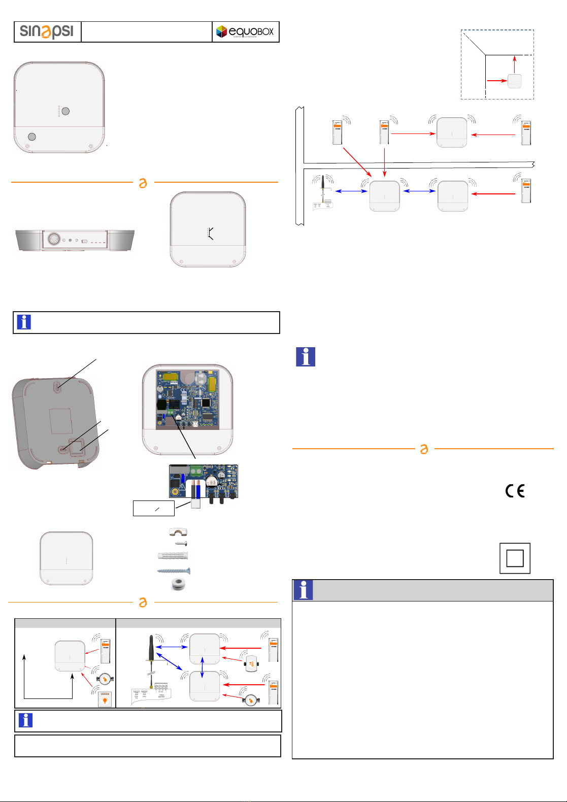
1.OVERVIEW
2.Connections/buttons/led lights
USB CONNECTION CONNECTION AT SIN.EQRTU1T
Before connecting anything, switch the power off, complete the cabling, close the lid and
power the device on.
TROUBLESHOOTING
1) The device does not start:
2) The blue LED light does not stop flashing:
3) Not all the meters are revealed:
3.WALL FASTENING AND CABLE PASS
Temperature range:
Ingress Protection:
Protection Class:
Fastening:
Dimensions:
Power supply:
Consumption:
Radio Frequency:
W. M-Bus Mode:
Max distance between
two RPT868XT:
7.TECHNICAL DATA
1
2
3
+55°C
SIN.EQRPT868XT - QuickStart Guide
-20°C
DOCUMENTATION DOWNLOAD: http://www.sinapsitech.it/en/area-download/
SIN.EQRPT868XT_QSG_2.5_en
Wireless M-Bus GATEWAY
Sinapsi Srl reserves the right to make changes to this product without any notice
- in case of network power supply, check that the power is on
- in case you are using a USB port, check the USB cable quality and that the PC is enabled to handle
500 mA of electrical power
- check that the meters that were not revealed are not too distant from SIN.EQRPT868XT or that
the signal is not disturbed by thick concrete or metal walls
- check that the devices are on the list loaded in SIN.EQRPT868XT or that the W. M-Bus devices
list receivable from SIN.EQRPT868XT is not blocked
- warning: some W. M-Bus devices transmit periodically (within hours)
- check that the MESH network is not interrupted using SIN.EQRTU1T web interface or SIN.EQSW1 sw
- W.M-Bus 868 MHz / OMS EN13757 data gateway
- Remarkable radio coverage due to multi-hop network
architecture (MESH)
- Manages up to 500 meters
- Last acquired data stored in a non-volatile memory
- Easy installation with software setup
- Simple and elegant design
- 100..240Vac power or via USB
- "Wall mounting" like installation
- USB interface for local data reading
- Optional WEB interface usable with SIN.EQRTU1T
12
1 - Power input 100..240Vac (with clips)
2 - Multifunction button
3 - Multifunction button
4 - Reset button
5 - USB port
34
6 - MESH network TX-RX LED
7 - W. M-Bus network TX-RX LED
8 - Signal/reception level LED
9 - State LED
5
67
8
SIN.EQRPT868XT gateway devices are provided with a MESH- ID=1 and channel 13.
Make sure that all the gateways and/or SIN.EQRTU1T have the same MESH network ID and radio
channel through SIN.EQSW1
Operative: -20°C ... +55°C
Storage: -25°C ... +85°C
IP 40 (EN60529)
II
wall clipped
LxHxP 160x160x35mm
100..240Vac 50/60Hz
USB (5Vdc, 500mA) for commissioning
4.5W
868MHz - Max transmission power: 27dBm
S / T / C +T / S & C+T
500mt free field - 40mt in building
- check that the device SIN.EQRTU1T is on and that the antenna is connected and in good position
(avoid placing it in switchboards or shielded environments)
- 1 blink "RAM memory error", 2 blinks "W.M-Bus radio module error",
3 blinks "MESH radio module error", 4 blinks "FLASH memory error", 5 blinks "Real Time Clock error"
- If turning offand restarting the SIN.EQRPT868XT, the error does not reset, the hardware must be replaced.
- check that SIN.EQRPT868XT is at least 5 metres distant from SIN.EQRTU1T and from other SIN.EQRPT868XT
- check that the ID and the MESH network channel are correct using SIN.EQSW1 sw and are the same ones
used by SIN.EQRTU1T
1 - upper hole
2 - low pre-hole
3 - cable pass pre-hole
4 - power supply connection
6. GATEWAY NETWORK CONFIGURATION
1. Power on SIN.EQRTU1T, connect to web interface and start antenna and device scan following the user’s manual
2. Power on the first device SIN.EQRPT868XT to be installed and move it away to a minimum distance of 5 metres
from SIN.EQRTU1T
3. Fixed blue SIN.EQRPT868XT LED shows the connection to the MESH network
4. Once connected, it shows the MESH radio signal quality to the gateway, by turning on the green
front LED, 1 – insufficient reception, 2 – sufficient, 3- good, 4 – excellent
5. Put SIN.EQRPT868XT in a place where the reception signal is >=2 and the reception of all the W. M-Bus
devices you expect to receive with this antenna is satisfactory
6. Check through SIN.EQRTU1T web interface or through SIN.EQSW1 software and a PC connected to the antenna
by USB that W. M-Bus devices, that you want to receive, reach the SIN.EQRPT868XT
7. Fasten the SIN.EQRPT868XT and proceed with powering a second gateway keeping it at least 5 metres away from
both the SIN.EQRPT868XT and SIN.EQRTU1T
8. Once connected, it shows the MESH radio signal quality to the gateway, by turning on the front LED,
so proceed as for the first SIN.EQRPT868XT.
a) The scanning phase is 12 hours. You can modify its duration through SIN.EQRTU1T
b) You can have various independent SIN.EQRPT868XT networks in the same building. In that case,
you need to have different ID or channel for each SIN.EQRPT868XT group and the relative SIN.EQRTU1T.
You can modify these parameters through SIN.EQSW1 software installed on a pc and connected via USB to
SIN.EQRPT868XT, see user’s manual for details.
c) In case the receiver receives more than 500 W. M-Bus devices or it receives devices belonging
to other plants, it might be necessary to make it selective. Therefore, you can load a list of W. M-Bus devices
marked by their serial number through SIN.EQSW1 software.
In this way, the gateway will receive the data exclusively from the listed devices.
d) The USB / Mini USB cable is not included and is not present in the package.
2 x Anchor 5x25
2 x Screws 5x30
2 x Glands
1 x SIN.EQRPT868XT
4.PACKAGE CONTENT
N
Power
supply
connection
2 x Screw 2,2x9,5
1 x clamp headband
SIN.EQRTU1T
MIN 5 m
MIN 5 m
MIN 5 m
USB
Mini USB
5.POSITIONING AND OPERATING DISTANCES
MAX 25 m MAX 25 m
SIN.EQRTU1T
SIN.EQRPT868XT
FLOOR 1
FLOOR 0
MAX 15 m
SIN.EQRPT868XT
FASTENING
WALL
WALL
CEILING
MIN
20 cm
MIN
20 cm
1) Fix the SIN.EQRPT868XT gateway on fastening wall at a minimum
distance of 20 cm from the ceiling and from the adjacent wall.
2) The maximum operating distance between the devices
installed on the same floor is 25 meters, with no major
obstacles such as reinforced concrete or metal walls, columns
or beams or other metal structures.
3) The maximum operating distance between the devices
installed on different floors is 15 meters.
MIN 5 m
SIN.EQRPT868XT
MIN 5 m
SIN.EQRPT868XT
MAX 25 m
MAX 15 m
Manufactured by SINAPSI SRL - Via delle Querce 11/13 - 06083 Bastia Umbra (PG) - Italy
For details on the configuration of the SIN.EQRPT868XT using the buttons, see the back of this
document, in the dedicated section.
L
max 2x1,5 mm2
o 6 mm
4
SIN.EQRPT868XT - QuickStart Guide
SIN.EQRPT868XT_QSG_2.5_en
Wireless M-Bus GATEWAY
DOCUMENTATION DOWNLOAD: http://www.sinapsitech.it/en/area-download/
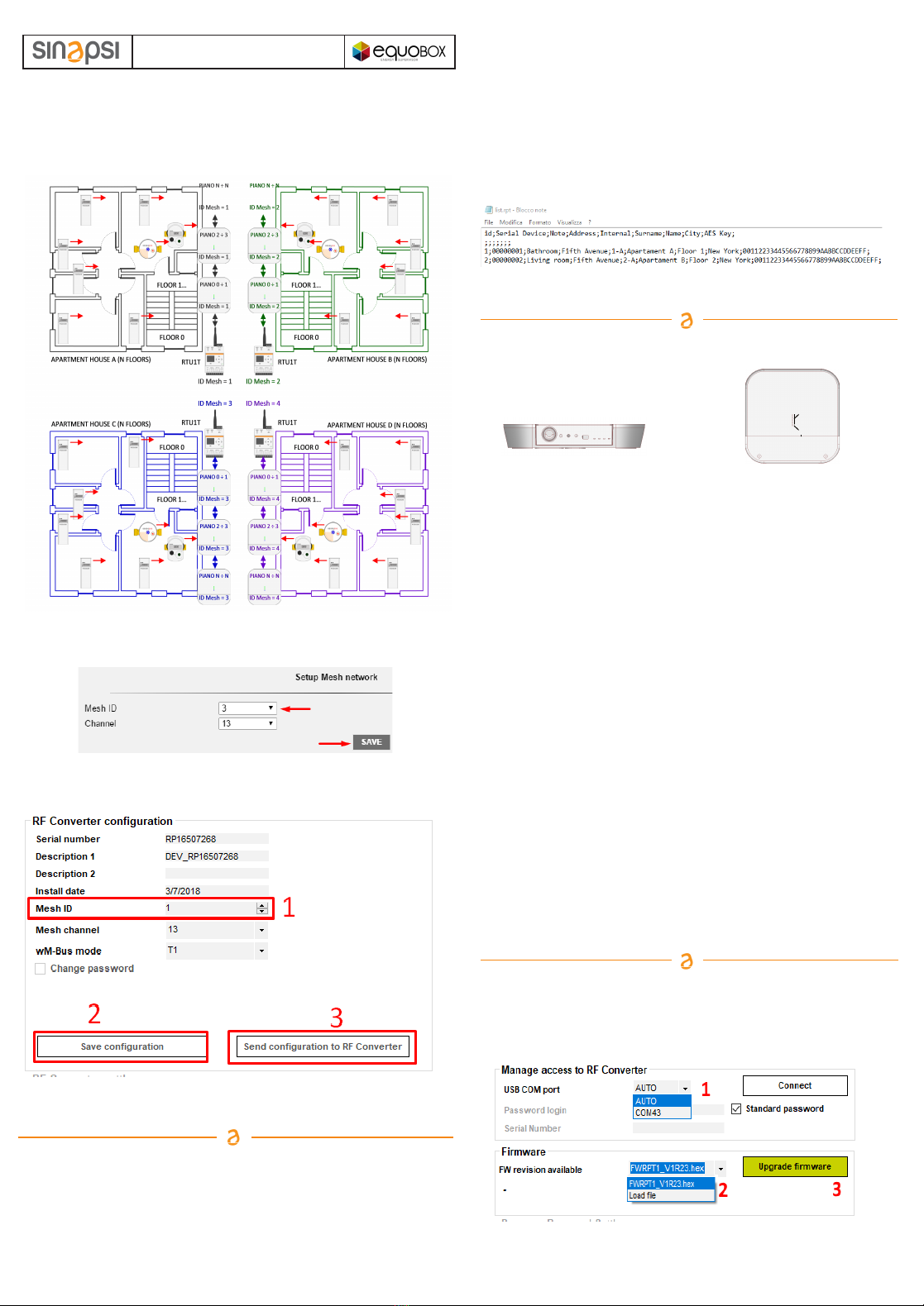
those exceeding 500 are ignored, and may in fact belong to the plant to be checked.
In this case it is necessary to charge, in the same Gateway, a file with a list of devices that are part of
its plant (Maximum 500); after uploading the file, the signal of the devices that are not included in the list
is ignored by the Gateway.
The file, whose name must be list.rpt, must be a CSV file with a format such as the one shown in the
following figure.
SPECIAL CASES OF USE
The following image shows an installation in which, or for different properties reasons , or for number of
devices to be controlled exceeds 500 (Max 500 for each RTU1T), it is necessary to create four
different networks of SIN.EQRPT868XT Gateways.
Obviously the following is valid also in cases where there are 2, 3, 5 or a higher number of Gateways
networks.
In order to avoid interferences between the various systems, assign to each RTU1T a different Mesh
network ID. The setting is done on RTU1T through its web interface; Settings / Wireless Devices /
Wireless Setup / Setup Mesh Network.
The same Mesh network ID setting must be carried out also on all Gateways that are part of the
network of the RTU1T which they have to communicate with.
For this procedure it is necessary to connect a PC to the Gateway to be configured (via USB cable).
Use the SIN.EQSW1 software (downloadable from the dedicated section of sinapsi.store) and follow
the instructions in the manual.
Note: It is recommended not to change the Mesh Network Channel (default = 13 both on RTU1Ts
and on Gateways), because the change may involve the transmission power of the devices.
LOADING ON GATEWAYS OF A W. M-Bus DEVICES LIST IN THE PLANT
(ONLY ON GATEWAYS WITH FIRMWARE VERSION FWRPT1_V1R20.hex ONWARDS)
Referring to the same image of the previous installation, the various Gateways receive W. M-Bus signal
from their plant devices but they can also receive the signal from devices of adjacent plants.
If one or more Gateways receive the signal from more than 500 devices (Max 500 for each gateway),
For this procedure it is necessary to connect a PC to the Gateway to be configured (via USB cable).
Use the SIN.EQSW1 software and follow the instructions in the manual.
GATEWAY CONFIGURATION THROUGH FUNCTIONALITY OF KEYS
GATEWAYS FIRMWARE UPGRADE
You should always check the possible release of the latest firmware available version of the Gateways,
compared to the one installed on the devices in the production phase.
For this procedure it is necessary to connect a PC to the gateway to be configured (via cable
USB). Use the SIN.EQSW1 software (downloadable from the dedicated section of sinapsi.store) and
follow the instructions in the manual.
SETTING OF MESH NETWORK ID
Sinapsi Srl reserves the right to make changes to this product without any notice
Manufactured by SINAPSI SRL - Via delle Querce 11/13 - 06083 Bastia Umbra (PG) - Italy
Change ID MESH - SIN.EQRPT868XT
1. Press keys 2 and 3 (2s. < T <6s) simultaneously.
2. On release all the LEDs (8) will flash at the same time to indicate
that you have entered edit mode ID MESH
3. Now press button 3 (at least 1s.) to switch the ID MESH.
- ID MESH 1 => Green LED (8.1) on - the others off
- ID MESH 2 => Green LED (8.2) on - the others off
- ID MESH 3 => Green LED (8.3) on - the others off
- ID MESH 4 => Green LED (8.4) on - the others off
4. To SAVE press keys 2 and 3 simultaneously for more than 1s.
Press the 2 button to exit without saving.
5. Verify that the blue LED does not remain on steady.
Otherwise, restart from point 1. by selecting another MESH ID.
6. If, after switching on all four MESH IDs, the blue LED continues to
remain on steady, it will be necessary to configure the
SIN.EQRPT868XT via SIN.EQSW1 software.
7. Repeat for each SIN.EQRPT868XT.
Activate SND_IR mode (Installation Mode) - SIN.EQRPT868XT
a) It typically involves the installation of the AMR system and
subsequently the installation of the heat cost allocators
b) Both the AMR system and the distributors must be configured to work
in this mode
c) SND_IR mode activation procedure on a newly installed
SIN.EQRPT868XT
1. Press button 2 (t> 6s.). When pressing button 2, the green LED (8.1)
flashes every second, until you are under the 6s. Once the 6s have
passed, the LED (8.1) flashes every 500ms => this indicates that the
"SND_IR" scan mode has been changed.
2. RPT enters the "SND_IR" scan mode. RPT receives and takes over all
the devices that transmit the installation W. M-Bus telegram.
(This frame contains no data)
3. Scan duration without user intervention 12 hours -> Manual stop of
the scan => press key 2 (no coded pressure time)
Note: SIN.EQRPT868XT automatically exits the SCAN mode after
12 hours.
Accept mode activation ALL - SIN.EQRPT868XT
a) It is used when the commissioning is carried out after with respect to
the installation of the heat cost allocators
b) To activate the accept ALL mode on a newly installed SIN.EQRPT868XT
1. Press button 2 (2s. < T < 6s)
2. When pressing button 2, the LED (8.1) flashes every second. When the
key 2 is released, the LED (8.1.) remains lit to indicate the activation of
the accept ALL mode.
3. RPT receives and takes charge of all devices transmitting in W.M-Bus
including frames in Installation Mode (SND_IR) - The first green LED
lights up permanently - Scan duration without user intervention 12 hours
4. press the button 2 (no coded pressure time) to stop the scan manually
Note: if during the scan the RPT connects into the MESH network the mode
of operation will automatically change with the value set on the RTU.
SIN.EQRPT868XT - S - T - C Mode of operation modification
1. Press keys 2 and 3 simultaneously (t > 6s.)
─during the simultaneous pressing of keys 2 and 3, the green LEDs
(8.1) and (8.2) will flash every second, until you are under the 6s.
Exceeded the 6s. they flash every 500ms
─When keys 2 and 3 are released, one of the green LEDs (8) starts to
flash (500ms) to indicate the currently active mode of operation on
that SIN.EQRPT868XT
2. The mode of operation is changed by pressing the 3 key briefly
• Mode C+T => Green LED (8.1) on - the other offFactory setting
• Mode S => Green LED (8.2) on - the other off
• Mode T => Green LED (8.3) on - the other off
3. save settings by pressing the 2 and 3 button (t> 2s.)
4. exit => key 2 for ESC function without saving (during programming
status). Automatic ESC from programming status after 10 minutes
later.
Note: SIN.EQRPT868XT automatically exits the SCAN mode after
12 hours.
Restore factory settings
1. Press and hold keys 2 and 3 simultaneously.
2. Then press the reset button 4, without releasing the keys 2 and 3
3. As soon as all the LEDs (8) and (9) flash quickly, release all three keys.
9
12
1 - 100..240Vac power supply input (screw clamps)
2 - “Multi-function” button
3 - “Multi-function” button
4 - Reset button
5 - USB Port
34
6 - MESH network TX-RX LED
7 - W. M-Bus network TX-RX LED
8 - Signal level LED
9 - Status LED
5
67
8
Popular Gateway manuals by other brands


DEUTSCHMANN AUTOMATION
DEUTSCHMANN AUTOMATION UNIGATE IC - EtherCAT instruction manual

Hitron
Hitron CODA-4*8 Series DOCSIS user guide

Onset
Onset Hobo MXGTW1 quick start

Multipipe
Multipipe 22-99998 installation manual

Teldat
Teldat bintec RT1202 manual

MDT Technologies
MDT Technologies SCN-MMG01.01 Technical manual


