Sinclair ASV-35BS User manual

Ver. | - -
User Manual
EN
CAMPER TRAILER
ASV-25BS (Wi-Fi)
ASV-35BS (Wi-Fi)
01
06
12
2021

„ORIGINAL INSTRUCTIONS“
IMPORTANT NOTE:
Read this manual carefully before installing or operating your new air conditioning unit.
Make sure to save this manual for future reference.

CONTENTS
This appliance is not intended for use by persons (including children) with reduced
physical, sensory or mental capabilities, or lack of experience and knowledge,
unless they have been given supervision or instruction concerning use of the
appliance by a person responsible for their safety. Children should be supervised
to ensure that they do not play with the appliance.
R32: 675
This appliance can be used by children aged from 8 years and above and persons
with reduced physical, sensory or mental capabilities or lack of experience and
knowledge if they have been given supervision or instruction concerning use of the
appliance in a safe way and understand the hazards involved.
Children shall not play with the appliance.
Cleaning and user maintenance shall not be made by children without supervision.
When refrigerant leaks or requires discharge during installation, maintenance, or
disassembly, it should be handled by certified professionals or otherwise in
compliance with local laws and regulations.
This marking indicates that this product should not be disposed with other household
wastes throughout the EU. To prevent possible harm to the environment or human
health from uncontrolled waste disposal, recycle it responsibly to promote the sustainable
reuse of material resources. To return your used device, please use the return and
collection systems or contact the retailer where the product was purchased. They can
take this product for environmental safe recycling.
TROUBLESHOOTING GUIDE ............................................................................................19
ERROR CODE ....................................................................................................................20
ELECTRICAL DATA ..............................................................................................................1
SPECIALIST’S MANUAL ....................................................................................................22
PACKING LIST ......................................................................................................................3
A FEW WORDS ABOUT YOUR NEW AIR CONDITIONING UNIT .......................................1
PARTS NAME........................................................................................................................4
OPERATION OF WIRELESS REMOTE CONTROLLER ......................................................5
ELECTRIC DIAGRAM ...........................................................................................................2
CONTROL PANEL ................................................................................................................9
INSTALLATION INSTRUCTION..........................................................................................10
NORMAL MAINTENANCE PROCEDURES .......................................................................21
STEP 3-MOUNTING OUTDOOR UNIT..........................................................................................14
STEP 4-INSTALLING THE CEILING ASSEMBLY .............................................................................15
STEP 5-ELECTRICAL WIRING
..................................................................................................16
STEP 6-COMPLETING THE INSTALLATION .................................................................................18
STEP 2-SELECTING AN INSTALLATION LOCATION & INSTALLING THE ROOF TOP AIR CONDITIONER ......10
STEP 1-STICK SPONGE (SEALING STRIP) AND SPONGE ON THE OUTDOOR UNIT ...............................10

THE REFRIGERANT
WARNING
Appliance filled with flammable gas R32.
Before install and use the appliance, read the owner’s manual first.
Before install the appliance, read the installation manual first.
Before repair the appliance, read the service manual first.
To realize the function of the unit, a special refrigerant circulates in the system. The
used refrigerant is the fluoride R32, which is specially cleaned. The refrigerant is
flammable and inodorous. Furthermore, it can lead to explosion under certain
conditions.But the flammability of the refrigerant is very low. It can be ignited only
by fire.
Compared to common refrigerants, R32 is a nonpolluting refrigerant with no harm
to the ozonosphere. The influence upon the greenhouse effect is also lower. R32
has got very good thermodynamic features which lead to a really high energy effi-
ciency. The units therefore need a less filling.
Appliance filled with flammable gas R32.
regralaeraroolfahtiwmooraniderotsdnadetarepo,dellatsniebllahsecnailppA
than 4 m
2
.
.secruosnoitingignitarepoylsuounitnoctuohtiwmooraniderotsebllahsecnailppaehT
( for example: open flames, an operating gas appliance or an operating electric heater.)
The appliance shall be stored in a well-ventilated area where the room size corresponds
to the room area as specified for operation.
.gnirruccomorfegamadlacinahcemtneverpotsaosderotsebllahsecnailppaehT
Ducts connected to an appliance shall not contain an ignition source.
Keep any required ventilation openings clear of obstruction.
Do not pierce or burn.
Be aware that refrigerants may not contain an odour.
esohtnahtrehto,naelcotrossecorpgnitsorfedehtetareleccaotsnaemesutonoD
recommended by the manufacturer.
Servicing shall be performed only as recommended by the manufacturer.
Should repair be necessary, contact your nearest authorized Service Centre.
Any repairs carried out by unqualified personnel may be dangerous.
Compliance with national gas regulations shall be observed.
Read specialist’s manual.

INSTALLATION PRECAUTION
Working temperature range
WARNING:
Otherwise, the cool air can’t be blown out and there will be condensate water on the
Before turning on the unit, please open the horizontal louver of indoor unit by hand.
horizontal louver.
Observe all governing codes and ordinances.
Do not use damaged or non-standard power cord.
Be caution during installation and maintenance. Prohibit incorrect operation
to prevent electric shock, casualty and other accidents.
Suggested working temperature range: -5 ~ 46℃. (heating: -5~24℃/cooling: +18~46℃).
Outdoor unit may stop operation, due to various kinds of protection within working
temperature range.
1. The place with strong heat sources, vapors, flammable or explosive gas, or
2.
5. The place with sulfureted gas.
6. Other places with special circumstances.
7.
volatile objects spread in the air.
The place with high-frequency devices (such as welding machine, medical equipment).
The place near coast area.
The place with oil or fumes in the air.
This air conditioner unit is only used for the vehicle without concave and convex
surface on the top of it.
8.
9.
Prohibit operating this air conditioner unit when starting up the vehicle or when the
vehicle is driving.
Prohibit supplying the power for the air conditioner unit with the vehicle power supply.
Requirement of air conditioner
1.
2. Select a location where the noise and outflow air emitted by the outdoor unit will
Air inlet should be far away from obstacles and do not put any objects near air
not affect neighborhood.
outlet. Otherwise, it will affect the radiation of heat-removal pipe.
3.Please try your best to keep far away from fluorescent lamp.
4.
Selection of Installation Location
3.
The appliance shall not be installed in the laundry.
4.
Basic requirement
Installing the unit in the following places may cause malfunction. If it is unavoidable,
please consult the local dealer:

Requirements For electric Connection
Safety precaution
8. The yellow-green wire or green wire in air conditioner is grounding wire, which
9.
10. The appliance shall be installed in accordance with national wiring regulations
3.
Must follow the electric safety regulations when installing the unit.
Properly connect the live wire, neutral wire and grounding wire of power socket.
Be sure to cut off the power supply before proceeding any work related t o electricity and safety.
4.
5.
with specialized grounding device by a professional. Please make sure it is
always grounded effectively, otherwise it may cause electric shock.
can't be used for other purposes.
The grounding resistance should comply with national electric safety regulations.
1.
For appliances with type Y attachment,the instructions shall contain the
substance of the following.If the supply cord is damaged,it must be replaced by
avoid a hazard.
INSTALLATION PRECAUTION

AIR CONDITIONING UNIT
A FEW WORDS ABOUT YOUR NEW
1.
ELECTRICAL
DATA
2.
3.
4.
All wiring must be complied with local and national electrical codes. All wiring
must be installed by qualified electricians. If you have
any questions about the
following instructions, contact a qualified
electrician.
The wiring diagrams are located on the cover of the control box. The assembly unit
wire diagrams are located on the ceiling panel.
5.
If the supply cord is damaged, it must be replaced by the manufacturer, its service
agent or similarly qualified persons in order to avoid a hazard.
6.
The Electric schematic diagram are subject to change without notice. Please refer
to which one on the unit.
Check the available power supply and resolve any wiring problems BEFORE installing
and operating this unit.
- 1 -
This air conditioner is designed to operate from a 220-240V AC, 50Hz, 1 Phase
power supply.
An all-pole disconnection switch having a contact separation of at least 3mm in all poles should
be connected in fixed wiring.
Including an air switch with suitable capacity, Air switch capacity:10A.
Air switch should be included magnet buckle and heating buckle function, it can protect the
circuit-short and overload.
Thank you for choosing the Recreational Vehicle Air Conditioner.
This manual will supply you with all the information for installation, operation and maintenance.
Take a few minutes to discover how to get the most in cooling comfort and economic operation
from your new air conditioner.
Please keep this manual well for future reference.

ELECTRIC DIAGRAM
Roof Top Air Conditioner
- 2 -
Ceiling Assembly
AP2
LAMP
MODULE
OUTDOOR UNIT
AP1
DISPLAY
CN1
DISP1
BOARD RT1 ROOM
SENSOR
ROOM
AP3
WIFI
MODULE
WIFI
0
OPTIONAL
CONNECTOR
CONNECTOR
CAP. WH
BU
S
BU
R
C3
INDOOR UNIT
OUTROOM
SENSOR
N14WAY
VALVE
4-WAY
4YV
NCOMP
AC-L
PE
BU
BN
YEGN
AP1
TUBE SENSOR
OUTDOOR
RT1
TUBE
SENSOR
RT2
MAIN BOARD
RT3
(20K) (15K)(20K)
(WH) (BK)
VT VT
K7
DISP1
T-SEN
MOTOR
IN_FAN
0
0
0
C
RD
COMP
COMP.
L
N
POWER
PE
M2
YEGN
MOTOR
OUT_FAN
C2
RD BN
CAP.
M1
C1
RD BN
CAP.
FAN
YEGN
PE
OFAN

PACKING LIST
owner’s manual
Bolt sub-assy
M8X135
Mounting plate remote controller
Remote controller holder
Double-sided
gummed paper
Foam (accessory)
Sunk screw
(remote controller holder) Foam (up)
Mounting plate sub-assy
Insulating sheath
Tapping screwBolt sub-assy M6X25
Sponge (foam accessory)
Sponge (sealing strip) Sponge Bundle
battery
(AAA 1.5V)
- 3 -
LED

PARTS NAME
Indoor Unit
Filter sub-assy Air-in grille
LED indicator
Air-out grille
Control panel (membrane)
remote controller
Outdoor Unit
Outer case
Air-in grille
Drainage outlet Chassis
(Display content or position may be different from above
graphics, please refer to actual products)
- 4 -
NOTICE:
Actual product may be different from above graphics, please refer to actual
products.
LED

- 5 -
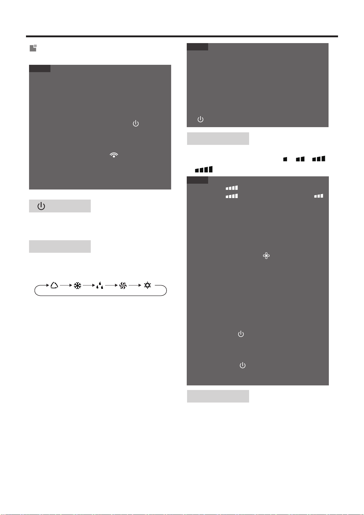
OPERATION OF WIRELESS REMOTE CONTROLLER
Introduction for icons on display
screen
Buttons on remote controller
Set temperature
WiFi function
Sleep mode
Light
Clock
Indoor ambient temp.
Set time
TIMER ON / TIMER OFF
Up & down swing
Child lock
Operation mode
Send signal
Auto mode
Cool mode
Dry mode
Fan mode
Heat mode
Set fan speed
LED
X-FAN function
●
●
AUTO COOL DRY FAN HEAT
●
●
●
●
●
MODE button
Press this button to select your required operation
mode.
Introduction for buttons on
remote controller
button
Press this button to turn on the unit. Press this button
again to turn off the unit.
●When selecting heat mode, the air conditioner
operates under heat mode. Press "+" or "-"
button to adjust set temperature. Press "FAN"
button to adjust fan speed.
When selecting auto mode, air conditioner will
operate automatically according to ambient tem-
perature. Set temperature can't be adjusted and
will not be displayed as well. Press "FAN" button
can adjust fan speed.
When selecting cool mode, air conditioner will
operate under cool mode. Press "+" or "-"
button to adjust set temperature. Press "FAN"
button to adjust fan speed.
When selecting dry mode, the air conditioner
operates at low speed under dry mode. Under
dry mode, fan speed can't be adjusted.
When selecting fan mode, the air conditioner will
only blow fan, no cooling and no heating. Press
"FAN" button to adjust fan speed.
,
to , then back to Auto.
This button is used for setting Fan Speed in the
sequence that goes from AUTO, ,
,
NOTE
This is a general use remote controller. It could be
used for the air conditioner with multifunction. For the
functions which the model doesn't have, if press the
corresponding button on the remote controller, the
unit will keep the original running status.
After putting through the power, the air conditioner
will give out a sound. Power indicator " " is ON.
After that, you can operate the air conditioner by
using remote controller.
Under on status, pressing the button on the remote
controller, the signal icon " " on the display of
remote controller will blink once and the air condition-
er will give out a sound, which means the signal has
been sent to the air conditioner.
FAN button
NOTE
●
●
●
●
For preventing cold air, after starting up heat mode,
indoor unit will delay 1~5 minutes to blow air (Actual
delay time depends on indoor ambient temperature).
Set temperature range from remote controller:
16~30℃(61-86℉).
This mode indicator is not available for some models.
Cooling only unit won't receive heat mode signal. If
setting heat mode with remote controller, press
" " button can't start up the unit.
NOTE
●
●
Under AUTO speed, air conditioner will select proper
fan speed automatically according to factory default
setting.
It's low fan speed under dry mode.
●AUTO speed is only available for some models.
- 6 -
- / + button
Press "+" or "-" button once increase or decrease
set temperature 1℃(℉). Holding "+" or "-" button, 2s
later, set temperature on remote controller will
change quickly. On releasing button after setting is
finished, temperature indicator on indoor unit will
change accordingly. (Temperature can’ t be adjust-
ed under auto mode)
When setting TIMER ON, TIMER OFF or CLOCK,
press "+" or "-" button to adjust time. (Refer to
CLOCK, TIMER ON, TIMER OFF functions).
●X-FAN function is only available for some models.
●Fan Speed " " is unavailable for some models,
Fan Speed " " is the same with Fan Speed " "
for some models.
●
●X-FAN function: Holding fan speed button for 2s in
cool or dry mode, the icon ""is displayed and the
indoor fan will continue operation for a few minutes in
order to dry the indoor unit even though you have
turned off the unit. After energization, X-FAN OFF is
defaulted. X-FAN is not available in auto, fan or heat
mode.
This function indicates that moisture on evaporator of
indoor unit will be blowed after the unit i s stopped to
avoid mould.
Having set X-FAN function on : After turning off the
unit by pressing " " button, indoor fan will continue
running for a few minutes at low speed. In this period,
hold fan speed button for 2s tostop indoor fan directly.
Having set X-FAN function off: After turning off the
unit by pressing " " button, the complete unit will
be off directly.

- 7 -
Sleep function
When selecting sleep function, sleep icon " "
flashes for 5s; press " SET " button within 5s to
turn on sleep function and " " icon is displayed
on remote controller. Press " SET " button again
within 5s to turn off sleep function and " " icon
disappears.
TIMER OFF function
Light function
Hold "+" or "-" button, 2s later, the time will change
quickly until reaching your required time.Press
"SET" button to confirm it within 5S. The word
"ON" will stop blinking.
Cancel TIMER ON: Press "MENU" button to
TIMER ON function and the characters "ON" flash-
es on the remote controller; press "SET" button
until the characters "ON" disappears.
●
NOTE
Some menu’s function may be unavailable under
different models.
MENU button
blank
No Setting
When selecting light function, light icon " "
flashes for 5s; press "SET" button within 5s to
turn off display light on indoor unit and" " icon
on remote controller disappears. Press “SET”
button again within 5s to turn on display light and
" " icon is displayed.
Press this button to select submenu function and
then press "SET"button to set the function
status of submenu. The submenu can be select-
ed circularly as follows:
TIMER
OFFON
TIMER
Ambient temperature display function
When selecting ambient temperature display
function, icon "" flashes for 5s; press "SET"
display on or off. After setting function on, the
"
button within 5s to select ambient temperature
" iconwill be displayed on remote controller
and you can see indoor ambient temperature on
indoor unit's displayer for a few seconds.
CLOCK function
TIMER OFF function can set the time for timer off.
Under TIMER OFF function status,"" icon
disappears and the word"OFF" on remote control-
ler blinks. Press "+" or "-" button to adjust TIMER
OFF setting. After each pressing "+" or "-" button
TIMER OFF setting will increase or decrease 1min.
Hold "+" or "-" button, 2s later, the time will change
quickly until reaching your required time, press
"SET" button to confirm it within 5S. The word
"OFF" will stop blinking.
Cancel TIMER OFF: Press "MENU" button to
TIMER OFF function and the characters "OFF"
flashes on the remote controller; press "SET"
button until the characters "OFF" disappears.
LED button
Press this button can turn on or turn off the LED light
on the panel.
up & down swing function
Not available for this unit.
CLOCK function can se
t
indi
clock
"
t
ime. Under
CLOCK function status, " " icon on remote con-
troller will blink. Press "+" or "-" button within 5s to
set clock time. Each pressing of "+" or "-" button,
clock time will increas e or decrease 1 min. If hold
"+" or "-" button , 2s later, time will change quick-
ly. Release this button when reaching your
required time, press "SET" button to confirm it
within 5S. The " " icon willstop blinking.
TIMER ON function
TIMER ONfunction can set the time for timer on.
UnderTIMER ON function status," " icon disap-
pears and the word"ON" on remote controller
blinks. Press "+" or "-" button to adjust TIMER ON
setting. After each pressing"+" or "-" button
TIMER ON setting will increase or decrease 1min.

- 8 -
TURBO button
Function introduction for
combination buttons
Child lock function
Temperature display switchover function
Under OFF status, press "-" and "MODE" buttons
simultaneously to switch temperature display
between ℃and ℉.
Press "+" and "-" simultaneously toturn on or
turn off child lock function. When child lock func-
tion is on, " " icon is displayed on remote control-
ler. If you operate the remote controller, the " "
icon will blink three times without sending signal to
the unit.
WiFi function
●This function is only available for some models.
NOTE
Under COOL or HEAT mode, press this button to
turn to quick COOL or quick HEAT mode. " "
icon is displayed on remote controller. If start this
function, the unit will run at super-high fan speed
to cool or heat quickly so that the ambient tem-
perature approaches the preset temperature as
soon as possible.
2.
1.
3.
battery
Replacement of batteries in
remote controller
Press the back side of remote controller
marked with " ", as shown in the fig, and then
push out the cover of battery box along the
arrow direction.
Replace two 7# (AAA 1.5V) dry batteries, and
make sure the position of "+" polar and "-" polar
are correct.
Reinstall the cover of battery box.
remove
reinstall
Cover of battery box
signal sender
●
●
●
●
●
●
During operation, point the remote control signal
sender at the receiving window on indoor unit.
The distance between signal sender and receiving
window should be no more than 8m, and there
should be no obstacles between them.
Signal may be interfered easily in the room where
there is fluorescent lamp or wireless telephone;
remote controller should be close to indoor unit
during operation.
Replace new batteries of the same model when
replacement is required.
When you don't use remote controller for a long time,
please take out the batteries.
If the display on remote controller is fuzzy or there's
no display, please replace batteries.
NOTE
NOTICE
●Fan Speed " " is unavailable for some models,
Fan Speed " " is the same with Fan Speed " "
for some models.
Press "MODE" and "TURBO" button simultane-
ously to turn on or turn off WiFi function. When
WiFi function is turned on, the "WiFi" icon will be
displayed on remote controller; Long press
"MODE" and "TURBO" buttons simultaneously
for 10s, remote controller will send WiFi reset
code and then the WiFi function will be turned on.
WiFi function is defaulted ON after energization
of the remote controller.

CONTROL PANEL
Note: If the remote controller is missing, operate on the control panel.
6
5 4 32 1
ON/OFF
indicator
temp.
indicator
COOL
indicator
receiver
window
HEAT
indicator
2LIGHT button
Press this button to turn on or turn off display
light on indoor unit.
3(+/-) button
4FAN SPEED button
Select the fan speed LOW, MED, HIGH and TURBO
(This function is applicable to partial of models) in
sequence.
Press the + button to increase the set(operating)
temperature of the unit,and press the - button to
decrease the set(operating) temperature of the
1ON/OFF button
Operation starts when pressing this button, and
stops when pressing this button again.
5MODE button
Select the operation mode, COOL,FAN,
HEAT.
6FILTER CHECK indicator
This feature is a reminder of cleaning the air
filter(normal maintenance) for more efficient
operation. The light will turn on automatically
after the fan works more than 250 hours.
If the light is on, turn off and power off the
unit, take the air filter out and clean it, then
re-install the air filter, power on and turn
on the unit, the light will still be on, press
+ button for 5s,the light will turn off.
unit. the temperature setting range is from 16~30℃
o
(61~86 F).
- 9-

INSTALLA TION
BEFORE INSTALLATION
Test run the unit with proper power supply. Refer to the operation instruction section in the Owner’s
Manual Operation & Installation. Make sure all the controls operate correctly then disconnect the
power supply of the unit.
- 10 -
WARNING
Sticking position
of sponge
(sealing strip)
Figure 1
1.
Sticking position of
three pieces of sponge
2.
Before sticking, clean up the sundries
at the sticking position (as shown in
Figure 1) of the chassis of the outdoor
unit to ensure that the sticking position
is clean;
3. Check whether the sponge (sealing strip)
and the sponge are tightly adhered, and
ensure that they will not fall off.
Take out one piece of sponge (sealing
strip) and three pieces of sponge from
the accessories, and tear off the paper
on the glue surface and align at the edge
of the position as shown in Figure 1 to
stick the sponge.
If the sponge (sealing strip) is damaged
or not stuck on the proper position, you
must replace it with a new one and stick
it properly;
STEP 2-SELECTING AN INSTALLATION LOCATION &
INSTALLING THE ROOF TOP AIR CONDITIONER
Your air conditioner has been designed for use in recreational vehicles.
Check the roof of the vehicle to determine if it can support both the roof top unit and the ceiling
assembly without additional support. Make sure the interior ceiling mounting area will not
interfere with existing structures.
1. Moving parts may cause personal injury. Be careful when test the unit. Do not operate the unit
with exterior cover removed.
3. Please use the equipped mounting Plate for installation; otherwise, it may cause malfunction
or damage.
2. Outdoor unit can't be installed at the low recess of the roof of vehicle. It must be mounted at the
flat surface on the roof of vehicle to make sure the rain, car-washing water, condensate water,
etc. can be drained smoothly. No water is allowed to be accumulated around the outdoor unit;
otherwise, it will cause malfunction or safety hazards as the water will pour into the air conditioner.

1.
3.
2.
CASE B.
It must be capable of supporting both the
weight of the roof top air conditioner and
the interior ceiling assembly.
There must be an opening through the
frame for the power supply wiring.Route
the supply wiring through the frame at the
same time the support frame is being
installed.
- 11 -
If a roof vent opening is not used,a new opening(see figure 1-1)will be cut into the vehicle roof.
A matching opening will also have to be cut into the interior vehicle ceiling,be careful when
cutting the ceiling opening because if the ceiling opening is carpeted,snagging could occur. After
the opening in the roof and interior ceiling are the correct size,a framed support structure must
be placed between the exterior roof top and interior ceiling.The reinforced framed structure must
follow the following guidelines:
It must be capable of holding the roof outer
surface and interior ceiling apart and
supporting them, so that when the roof top
air conditioner and ceiling assembly are
bolted together,no collapsing occurs. A
typical support frame is shown in Figure 1-1 .
400mm
400mm
19mm
25mm
Figure 1-1
Hole for
Wires
CASE A.
1.
2.
If a roof vent is already present in the desired mounting location for the air conditioner the
following steps must be performed:
3.
It may be necessary to seal some of the old roof vent mounting screw holes which may
fall outside of the air conditioner basepan gasket.
Remove all screws which secure the roof vent to the vehicle. Remove the vent and any
additional trim. Carefully remove all chalking from around the opening so the surface is
clear.
Examine the roof opening size, if the opening is small than 400x400mm, the opening
must be enlarged.
Once the location for your air conditioner has been determined. A reinforced and framed roof.
Hole must be cut (if there is no hole, please refer to CASE B) or you may use existing vent
holes (See CASE A).

2.
3.
4.
Check whether there are holes or grooves on
surface of installation position. If yes, conduct
the sealing treatment to prevent water leakage;
- 12 -
CAUTION
Fill the groove on the surface where the mount-
ing plate is contacting the top part of the vehicle
with the unhardened sealant (the maximum
thickness is 1cm); When the mounting plate is
installed on the top of vehicle, fill the sealant in
the gap between the mounting plate and the
vehicle roof. The mounting plate should be
tightly sealed with the roof of the vehicle to
prevent water leakage.
1.
2.
3.
4.
Install it into the opening on the top of the vehicle
according to the indicate direction by the arrow
(the direction of arrow should be the same with
the head of the vehicle).
The roof top air conditioner must be mounted on a level plane from front to rear and side to
side when the vehicle is parked on a level plane. Figure 2 shows maximum allowable degrees
that the unit can be mounted above or below level.
.The front section of outdoor unit of air conditioner must be in the same direction as the vehicle,
which is useful for reducing wind resistance.
If the roof of the vehicle is sloped (not level) such that the roof top air conditioner cannot be
mounted within the maximum allowable degree specifications, an exterior leveling shim will
need to be added to make the unit level. A typical leveling shim is shown in Figure 3.
Once the roof top air conditioner has been leveled, some additional shimming may be required
above the interior ceiling assembly. The roof top air conditioner and the interior ceiling assembly
must be square with each other before they are secured together.
After the mounting hole area is properly prepared, remove the carton and shipping pads from
around the roof top air conditioner. Carefully lift the unit on top of the vehicle. Do not use the outer
plastic shroud for lifting. Place the roof top air conditioner over the prepared mounting hole.
400mm
400mm
Figure 1-2
INSTALLATION METHOD FOR MOUNTING PLATE.
If the roof already has a 400x400mm opening.
Select the installation position for the recreational vehicle air conditioner
This mounting plate of switchover opening is applicable for Sinclair recreational vehicle air conditioner.
The opening size of installation port on the top of the vehicle must be 400×400mm.
Operation method:
1. Eliminate the sundries around the installation
port on the top of the vehicle and keep the
installation surface flat;

- 13-
400mm
400mm
Above or Below
Level
Note: Try you best to put the unit on the horizontal surface for operation. The unit can only operate for a short
Figure 2
Figure 3
Figure 4
Level
Height Varies to Make Unit Level
Level
Level
1077
(588)
400
400x400
OPENING
89
NOTE AIR CONDITIONER DIMENSIONS (ROOF OF UNIT)
720
Unit:mm

- 14-
STEP 3-MOUNTING OUTDOOR UNIT
1.Open the package and take out the outdoor
unit
2.Put the outdoor unit at the mounting plate of
switchover opening.
1) When taking out the outdoor unit after
unpacking, do not lift the air outlet grille at
the back of outer case
1) Lift the outdoor unit. During the movement,
it is strictly forbidden to hoist the plastic outer
caser of outer unit of the air conditioner.
2) Put it on the mounting plate of the prepared
switchover opening to make the sealing strip
of outdoor unit match with the groove on the
surface of the mounting plate.Do not drag the
outdoor unit. Otherwise, the seal may fall off.
(see Figure 4-1).
Figure 4-1
Figure 4-2
This manual suits for next models
1
Table of contents


