Active 1460 User manual

ELECTRO POWER TRACK 1460
I
OWNER’S MANUAL
MANUEL D’INSTRUCTION
F
GB
MANUALE D’ISTRUZIONE
EMANUAL DE INSTRUCCIONES
DGEBRAUCHSANWEISUNG

FIG. 1 FIG. 2
FIG. 3
FIG. 4
FIG. 5 FIG. 6
10
4
16
2
17
ABCD
18
14
19 20
7
11

FIG. 7 FIG. 8
FIG. 9 FIG. 10
FIG. 12
FIG. 13
FIG. 11
FIG. 14
21
21
21
22
23
24
25
10
E
F
G
H
26
L
M
27
28
29
30
32
31
33
33
32
31 34
35

Caro cliente, la ringraziamo vivamente per aver scelto un prodotto di qualità della dittaACTIVE.
Per un corretto impiego del POWER TRACK e per evitare incidenti, non iniziate il lavoro senza aver letto questo manuale con
attenzione. Troverete su questo manuale le spiegazioni di funzionamento dei vari componenti e le istruzioni per i necessari controlli
e per la manutenzione.
N.B. : La casa produttrice si riserva la possibilità di apportare eventuali modifiche in qualsiasi momento e senza preavviso.
(INDICE PAG.6)
INTRODUZIONE
I
GB
F
E
INTRODUCTION
Dear Customer, Thank you very much for choosing a qualityACTIVE product.
For correct use of POWER TRACK and to avoid accidents, do not start work without having carefully read this manual. In this
manual, you will find explanations regarding operation of the various components and instructions for necessary inspections and
maintenance.
NOTE: The manufacturer reserves the right to make changes at any time and without notice.
(INDEXPAGE 14)
INTRODUCTION
Cher client, nous vous remercions vivement d’avoir choisi un produit de qualité de l’entrepriseACTIVE.
Pour une utilisation correcte du POWER TRACK et pour éviter tout incident, ne commencez pas le travail sans avoir lu ce manuel
attentivement. Vous trouverez dans ce manuel les explications de fonctionnement des divers composants et les instructions pour
les contrôles nécessaires et pour l’entretien.
N.B. : L’entreprise de production se réserve la possibilité d’apporter d’éventuelles modifications à tout moment et sans préavis.
(INDEXPAGE 22)
INTRODUCCIÓN
Estimado cliente, en primer lugar queremos agradecerle por haber elegido un producto de calidad marcaACTIVE.
Para un correcto uso del POWER TRACK y para evitar accidentes, no iniciar a trabajar sin haber leído atentamente antes este
manual. Dentro de este manual encontrará todas las explicaciones acerca del funcionamiento de los diversos componentes y las
instrucciones para realizar los controles necesarios y su mantenimiento.
NOTA: La casa fabricante se reserva la posibilidad de aportar posibles modificaciones en cualquier momento y sin aviso previo.
(ÍNDICEPAG. 30)
EINLEITUNG
Sehr geehrter Kunde, vielen Dank, dass Sie sich für ein Qualitätsprodukt von ACTIVE entschieden haben. Um den
ordnungsgemäßen Betrieb des POWER-TRACK zu gewährleisten und Unfälle zu vermeiden, beginnen Sie erst mit derArbeit,
wenn Sie dieseAnleitung sorgfältig und vollständig gelesen haben. Sie finden in dieserAnleitung die Erklärungen zum Betrieb der
einzelnen Komponenten sowieAnweisungen für die erforderlichen Kontrollen und Wartungsarbeiten.
HINWEIS : Der Hersteller behält sich das Recht vor, Änderungen jederzeit und ohneAnkündigung vorzunehmen.
(ÍNDICEPAG. 39)
D

INDICE
1.Datitecnicie Dichiarazionediconformità..........................................................................................................................................Pag.6
2.Spiegazionesimboli.........................................................................................................................................................................................7
3.Comandi............................................................................................................................................................................................................8
4.Norme disicurezza...........................................................................................................................................................................................8
5.Avanzamentomacchia.....................................................................................................................................................................................9
6.Funzionamentodelveicoo.............................................................................................................................................................................9
7.Pianale dicario...............................................................................................................................................................................................10
8.Manutenzioneperiodica...............................................................................................................................................................................10
9.Climafreddo....................................................................................................................................................................................................11
10.Anomaliedi funzionameno.........................................................................................................................................................................11
11.Rimesaggio...................................................................................................................................................................................................12
12.Certificato digarania...................................................................................................................................................................................13
I
1.Technical Data and Declaration ofConformity...........................................................................................................................Page 14
2.Explanation ofsymbols............................................................................................................................................................................15
3.Controls......................................................................................................................................................................................................16
4.Safety regulations.....................................................................................................................................................................................16
5.Machine drive............................................................................................................................................................................................17
6.Vehicleoperation.......................................................................................................................................................................................17
7.Loading platform.......................................................................................................................................................................................18
8.Routine maintenance................................................................................................................................................................................18
9.Cold climate................................................................................................................................................................................................19
10.Troubleshooting.....................................................................................................................................................................................19
11.Storage......................................................................................................................................................................................................20
12.Certificate of warranty............................................................................................................................................................................21
GB INDEX
1.Données techniques et Déclaration de conformité...................................................................................................................Page 22
2. Explication des symboles........................................................................................................................................................................23
3.Commandes................................................................................................................................................................................................24
4.Normes desécurité....................................................................................................................................................................................24
5.Entraînement de lamachine.....................................................................................................................................................................25
6.Fonctionnement du véhicule...................................................................................................................................................................25
7.Plateforme de chargement........................................................................................................................................................................26
8.Entretien périodique..................................................................................................................................................................................26
9.Climatfroid.................................................................................................................................................................................................27
10.Anomaliesde fonctionnement...............................................................................................................................................................27
11.Remisage...................................................................................................................................................................................................28
12.Certificat de garantie...............................................................................................................................................................................29
FINDEX

1.Datos técnicos y Declaración de conformidad.............................................................................................................................Pág.30
2.Explicación de lossímbolos.....................................................................................................................................................................31
3.Mandos.......................................................................................................................................................................................................32
4.Normas de seguridad................................................................................................................................................................................32
5.Funcionamiento de lamáquina................................................................................................................................................................33
6.Funcionamiento delvehículo...................................................................................................................................................................33
7.Plataforma de cargamento........................................................................................................................................................................34
8.Mantenimiento periódico.........................................................................................................................................................................34
9.Climafrío.....................................................................................................................................................................................................35
10.Anomalíasde funcionamiento...............................................................................................................................................................35
11.Arreglos....................................................................................................................................................................................................36
12.Certificado de garantía...........................................................................................................................................................................37
EINDICE
D
1.TechnischeDaten und Konformitätserklärung.............................................................................................................................Pág.39
2.Erklärung derSymbole..............................................................................................................................................................................40
3.Bedienelemente..........................................................................................................................................................................................41
4.Sicherheitsvorschriften............................................................................................................................................................................41
5.Vorschubder Maschine............................................................................................................................................................................42
6.Betrieb desFahrzeugs..............................................................................................................................................................................42
7.Ladepritsche...............................................................................................................................................................................................43
8.RegelmäßigeWartung..............................................................................................................................................................................43
9.Kaltes Klima...............................................................................................................................................................................................44
10.Betriebsstörungen..................................................................................................................................................................................44
11.Lagerung...................................................................................................................................................................................................46
12.Garantieschein.........................................................................................................................................................................................46
INHALT

I
ITALIANO
7
1.DATITECNICI EDICHIARAZIONEDI CONFORMITA’
ACTIVE s.r.l. via Delmoncello,12 - 26037 S. Giovanni in Croce (CR)
dichiara sotto la propria responsabilità che la macchina:
è conforme alla direttiva macchine 2006/42/CEE e 2004/108/CE
ALBERTOGRIFFINI
PRESIDENTE
ACTIVES.r.l.
Via Delmoncello, 12
26037 San Giovanni in Croce (CR) - ITALY
10/10/2008
MODELL ELECTRO POWER TRACK 1460
MOTOR WECHSELSSTROMMOTOR
STROMVERSORGUNG 2 GEL-BATTERIEN 85 Amp/h
LEISTUNG 3.0 KW / 4.1 CV
ANLASSERSYSTEM ELEKTRONISCH
ELEKTROMOTOR - GÄNGE 3 VW + 3 RR (elektrische
Umkehrvorrichtung)
FESTSTELLBREMSE TROMMELBREMSE
LADEGERÄT VERSORGUNG 220 V
VERBRAUCH 300 W / h
GESCHWINDIGKEIT 1 vw 1.93
2 vw 3.87
3 vw 6.0
1 rw 1.84
2 rw 3.68
RAUPENUNTERWAGEN BODENKONTAKTLÄNGE 820 mm
RAUPENBREITE 180 mm
ACHSABSTAND 490 mm
RAUPENMABE (Breite * Zahnabstand * Anzahl Zähne) 180 * 60 * 37
BODENDRUCK (ohne Last – Volllast ) 0.066 – 0.218 Kg/cm2
MAX GEFÄLLE ohne Last 25°
MAX GEFÄLLE bei Volllast 15°
MINDESTBODENFREIHEIT 50 mm
MAX ABMESSUNGEN Breite 670 mm
Länge 1670 mm
Griffhöhe 1000 mm
ERWEITERBARE LADEPRITSCHE Breite von … bis Von 670 bis 920 mm
Länge von … bis Von 900 bis 1020 mm
Stehhöe 200 mm
LADEPRITSCHE DUMPER Breite 660 mm
Länge 920 mm
Stehhöe 320 mm
Volumen 157 l
Blechdicke 2 mm
KIPPEN DER LADEPRITSCHE Manuale
GEWICHT 210 Kg
TRAGFÄHIGKEIT 450 Kg
IITALIANO
8
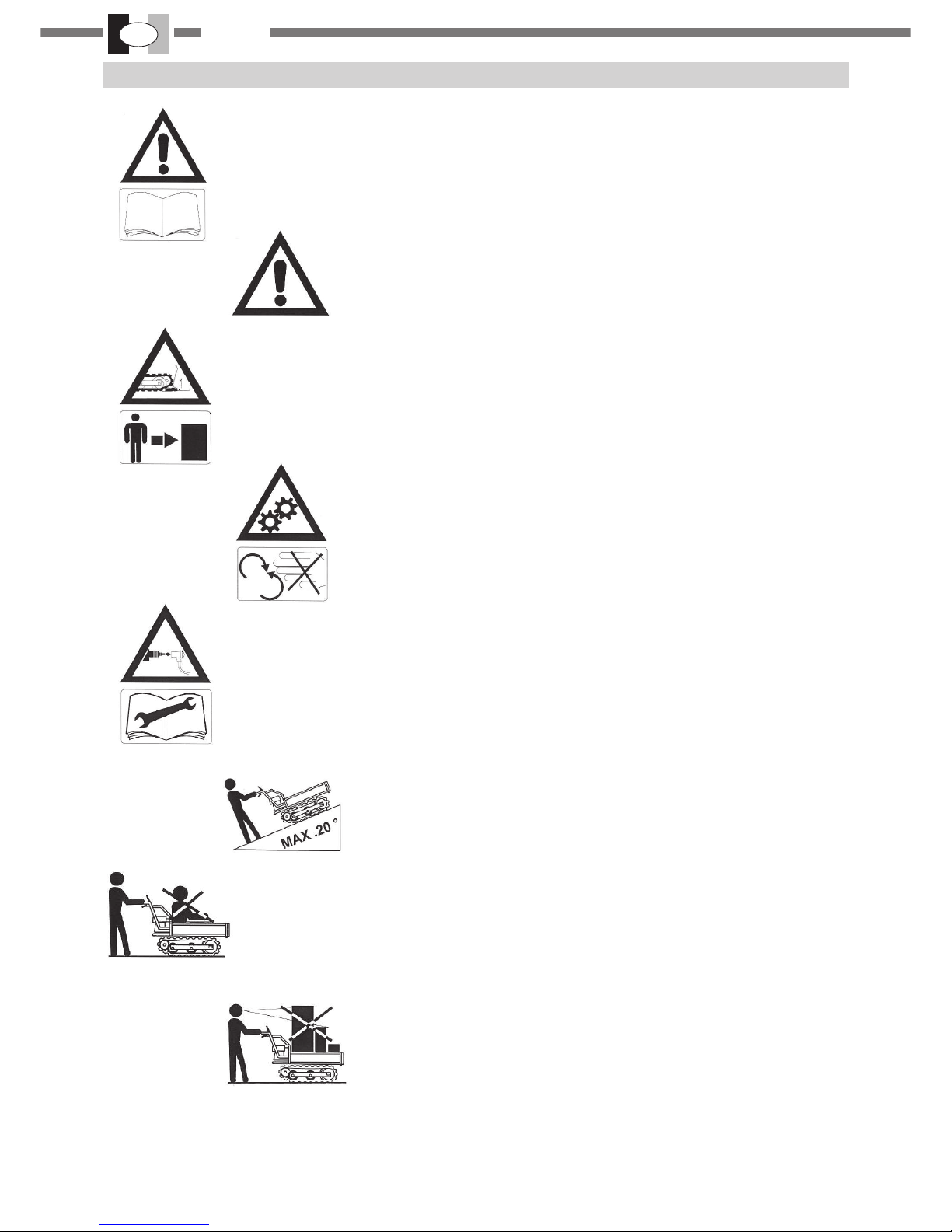
2.SPIEGAZIONESIMBOLI
Leggere il libretto uso e manutenzione prima di utilizzare questo veicolo.
Avvertenze, pericolo ed attenzione.
Pericolo, non avvicinate mani e piedi ai cingoli e per sicurezza man-
tenetepersone e animali a minimo5mt.didistanza.
Non rimuovere o manomettere carter o schermi di
sicurezza.
Prima di eseguire qualsiasi intervento di manutenzione o riparazione sul
veicolo, staccate il capuccio candela e consultate il libretto uso e manu-
tenzione.
Non superare pendenze superiori a 20°.
Non salite sulla macchina e non trasportate passeggeri.
Non accatastate i carichi troppo alti;
non solo restringerebbe il campo di visione
dell’operatore, ma renderebbe anche troppo alto
il centro di gravità compromettendo la stabilità del veicolo.
Non lavare con getti d’acqua o idropulitrice

I
ITALIANO
9
3. COMANDI
1
2
34
5
67
8
11
10
9
12 13 14
1-CASSONE
2-LEVASELEZIONEMARCECAMBIOMECCANICO
3-MOTOREELETTRICO
4-ACCELERATORE
5-FAROILLUMINAZIONEDILIVELLO
6-INDICATORELIVELLODICARICABATTERIA
7-INTERRUTTOREMARCIAAVANTI/INDIETRO
8-PRESAAUSILIARIA24VOLT
9-AVVISATOREACUSTICO
10-LEVADIAVANZAMENTO
11-CHIAVEON/OFFBATTERIA
12-INDICATORECARICABATTERIA
13-SPINACARICABATTERIE (da collegare a presa 220 volt)
14-COPERCHIOSCATOLAIMPIANTOELETTRICO
15-LEVADISTERZATA
4.NORMEDI SICUREZZA
1- Leggere attentamente queste istruzioni ed accer-
tarsi di comprenderle prima di far funzionare l’unità.
Attenersi a tutte le avvertenze ed alle istruzioni di
sicurezza. Conservare questo manuale a titolo di fu-
turo riferimento.
2- Usare solamente ricambi originali, pezzi di ricambio
prodotti da altri fabbricanti potrebbero adattarsi male e
causarelesioni.
3- Non permettere ad altre persone, bambini o ani-
mali di restare nel raggio di 5mt. durante l’uso della
macchina.
4- Nonoperareconlamacchinaquandosiè stanchi, ma-
lati o sotto l’effetto di alcool, droghe o farmaci.
5- Usare la macchina solamente per compiti indicati
dal presente manuale.
6-Ispezionare la macchina prima di ogniimpiego.Assicu-
rarsi che i dispositivi di sicurezza non siano allentati ecc..
Sostituirele parti danneggiate.
7- Prima di eseguire lavori prendere familiarità con
la macchina usandola in superfici piane e sgombre
da ostacoli.
8-Conlachiave(11)suONnonfarealcunamanutenzione.
9- Non trasportare persone o animali sia sulla mac-
china che sul pianale.
10- Guidaresempre il veicolo in avanti.Primadi innestare
la retromarcia (guida all’indietro) prendere le precauzioni
contro le cadute. Verificare che non ci siano ostacoli e
assicurarsi la massima visibilità.
11- Avviare o arrestare con cautela il veicolo su terre-
nisconessi.
12- Non cambiare velocità o fare inversioni ad “U” lungo i
pendii o su terreni sconessi.
13- Il sovraccarico è pericoloso. Caricate il veicolo
osservando la massima capacità di carico.
14- Non entrare in acqua se il livello è superiore ai 20 cm
15- Non spruzzare acqua in pressione sul motore elet-
trico o all’interno della cassetta contenente i circuiti
elettrici.
16- Nontrasportatecarichieccedentiledimensioniester-
nedel pianale.
17- Non accatastare i carichi troppo alti; non solo re-
stringerebbe il campo di visione dell’operatore, ma
renderebbe anche troppo alto il centro di gravità,
compromettendo la stabilità del veicolo.
18- Operare esclusivamente con la massima visibili-
tà.
19-Ilveicolononpuò operaresupendenzemaggioridi 20°
15
FIG. 14

IITALIANO
10
5.AVANZAMENTOMACCHINA
ATTENZIONE: leggereattentamentelenormedi
sicurezza. Se siete nuovi all’uso del veicolo se-
guiteil primo periodo di addestramento.
- Ispezionate sempre attentamente il veicolo prima
dell’uso.Verificate che non ci sianovitiallentate, partidan-
neggiateeperdited’olio.
-Controllareche i comandi funzionano correttamente.
AVVIAMENTO MOTORE (Fig. 1 - 2)
1-Assicurarsi che la leva acceleratore (4) sia in posizione
“minimo”.
2-Assicurarsichela leva diavanzamentorossa (10) sia in
posizione A“FOLLE” e cioè disinnesta.
3- Selezionare la leva delle marce del cambio meccanico
(2) : 1 avanti --> per salite molto rapide
2-3 avanti --> per gli altri casi.
4- Controllarela posizione dell’interruttoremarcia
avanti/indietro(7) : selezionareilverso avanti (oindietro).
5- Ruotarela chiave(11)sullaposizione ON
6-Premerelalevaavanzamento(10)
7- Ruotarelentamente la levaacceleratore (4)
8- Lamacchina incomincia a muoversi el’acceleratore(4)
permettedi scegliere la velocità desiderata.
9-Per invertire il senso di marcia selezionare l’interruttore
(7)sulla posizione indietro.
10-Incaso dipericolo lasciarerapidamente laleva diavan-
zamento (10): in questo modo il mezzo si arresta rapida-
mente.
11- Tuttele volte che la macchina rimane ferma è
necessarioruotarela chiave (11) sullaposizioneOFF:in
questo modo si evita di scaricare inutilmente le batterie.
ARRESTO MOTORE (Fig. 1 - 2)
1- Rilasciarelalevadiavanzamento(10)perildisinnesto
dellatrasmissione.
2- Posizionarela leva del cambio (2) inposizione“N” neu-
tra.
3- Portare la leva acceleratore (4) al minimo .
4- Ruotarela chiave (11)sulla posizione OFF
20- Quando scendete lungo un pendio, inserire la pri-
ma marcia o retromarcia, ricordandovi di utilizzare
il freno motore.
21-Nonguidaresupendiioveesistailrischiodiribaltamento
ocaduta del veicolo.
22- Il freno è inserito quando si disinnesta la leva (10).
Sui pendii, terreni sconnessi e quando si viaggia a
velocità elevata, fare attenzione alle frenate o
alle sterzate brusche poiché possono far ribaltare il
veicolo o far cadere il carico.
23- Posteggiare il veicolo su terreni piani e sicuri. Evitate
luoghipericolosi.
24- Quando posteggiate:
- su terreni in pendenza, usate i cunei di fermo per
bloccare il veicolo.
- rilasciate la leva frizione e fermate il motore.
6.FUNZIONAMENTODEL VEICOLO
1- Lamacchina è dotata diuncaricabatteria integrato (20)
fig.6,pertanto è consigliato dicaricarele batterie (18) fig.5
quando la macchina non viene utilizzata al fine di avere
semprea disposizione lamassima autonomia difunziona-
mento. Il caricabatterie deve essere alimentato a 220 ed
ha un consumo di 300 W/h. E’ anche possibile utilizzare
un inverter da 300 W da collegare all’impianto elettrico di
unautoo di un furgone.
2- Collegarela spina (13) ad una presadicorrente
220Volt
3- Durante la carica si accende una luce arancione e a
caricaavvenutasi accende una luce verde all’interno del-
l’indicatorecaricabatteria (12)
4- La macchina è dotata di faro d’illuminazione (5). Ricor-
darsi di spegnerlo se non è indispensabile l’uso.
L’autonomia difunzionamentodipende moltodaltipo d’im-
piego, dal tipo di percorso e dal peso caricato sul casso-
ne.
5- Scegliereun’appropriata velocità d’uso peril lavoro con
lalevadel cambio (2) fig.1.
ATTENZIONE:Serisultadifficileinnestareuna marcia,non
forzatela, ma innestate e poi disinnestate la leva di avan-
zamento rossa (10) fino a quando la marcia s’ innesta fa-
cilmente.Assicurarsi che la marcia sia innestata corretta-
mente.
ATTENZIONE : Se ruotatela chiave (11) su OFF e la leva
acceleratore non è in posizione MINIMO, alla succussiva
rotazione della chiave (11) su ON, la macchina, pur pre-
mendola levarossa(10), non avanzerà.
Pertantorilasciate la leva rossa(10)e portate al minimola
levaacceleratore (4)alMINIMO.
Quindipremete laleva rossa (10)e acceleratemediantela
leva(4) : la macchina cominceràadavanzare.
(Questa è una sicurezza per evitare l’avanzamento acci-
dentale alla massima velocità senza l’atto volontario del-
l’operatore).
6- Per l’arresto del veicolo rilasciare velocemente la leva
rossa(10).
ATTENZIONE:suterrenisconessi,usareilveicoloconlaprima
marcia(lenta).Noncambiaremarciadurantelaguida.
Evitareinversionia“U”edicambiareil rapportodivelocità.
7- Perregolarela velocità d’avanzamento spostare lenta-
mentela leva dell’acceleratore(4).
CAMBIO DI DIREZIONE
-Tirare laleva destrao sinistradellefrizioni laterali(15) per
sterzarenella direzione desiderata.
LEVADESTRA: il veicolo gira a destra
LEVASINISTRA: il veicologiraasinistra
Sele leve vengono tirate contemporaneamente, ilveicolo
siarresta immediatamente.
“DESTRA” e “SINISTRA” si riferiscono con l’operato-
re in posizione di guida e cioè impugnando il manu-
brio.
RETROMARCIA: prima di procedere in retromarcia assi-
curarsi che la zona dietro di voi sia sgombra di ostacoli e
chepossiate procedere nella massima sicurezza
ATTENZIONE quandosisupera la velocitàdisicu-
rezza ± 5km/ora la macchina non sterza.

I
ITALIANO
11
7.PIANALEDI CARICO
PIANALE ESTENSIBILE Fig. 7
-Il piano dicarico del veicoloèdotato di spondeestensibili
chepermettonodiadeguare ledimensioni delcassone alle
vostreesigenze di trasporto.
-Per variare le dimensioni delcassonesaràsufficiente al-
lentarei pomelli(21) edestrarre lasponda secondoneces-
sità.
CASSONETIPO DUMPER
- È disponibile a richiesta il cassone tipo dumper che per-
mette di trasportare anche carichi liquidi.
ATTENZIONE:perl’arrestodelveicoloprocedere
lentamente per evitare di ribaltare il carico.
- Assicurarsi che il pianale sia caricato correttamente.
Osservarela massima capacitàdicarico. Il sovraccaricoo
l’uso del veicolo oltre la massima pendenza consentita,
nonsolo deteriora il veicolomaespone l’operatore al peri-
colo di un ribaltamento del carico.
SCARICOMANUALE Fig. 14
-Sollevamento: premerelaleva disgancio (34) versol’im-
pugnatura(35) e sollevareilcassone.
- Abbassamento: tramite l’impugnatura (35) abbassare il
cassoneassicurandosiche ildispositivo dibloccaggiobloc-
chi il cassone.
ATTENZIONE:per lavostra sicurezzalo scaricodel
carico deve essere sempre effettuato su terreno
pianeggiantee aveicolofermo.
8.MANUTENZIONEPERIODICA
TRASMISSIONE (Fig.8)
-Verificareperiodicamente che non ci siano trafilamenti o
perdited’olio dalla trasmissione.
Tipoolio: olio SAE 80 / 90
Capacità: 1,5 litro
Cambioolio: dopo 50ore
Successivamenteogni 500 ore
Effettuare il cambio olio con la trasmissione calda.
- Posizionare un recipiente sotto il tappo (22)
- Togliere il tappo (22) e lasciare che il cambio si svuoti
completamente.
- montare il tappo (22) e bloccarlo.
-Togliere il tappo (23) e inserire lt.1.1 d’olio.
- montare il tappo (23) e bloccarlo.
REGISTRAZIONEDELLA CINGHIA DI TRASMISSIONE
Fig. 3 - 4
Nel caso in cui la cinghia slitti, cioè abbassando la leva
(10)in posizione“innestata” (F)vedifig. 11, eilveicolo non
simuova,allentarela 4 viti di fissaggio (A,B,C,D) che ten-
gono fissato il motore elettrico al telaio, spingere legger-
mentequest’ultimo in avantiversoil cassone e contempo-
raneamenteriavvitare la4viti di fissaggio.
REGISTRAZIONEDELFRENODISTAZIONAMENTO
Fig. 11 - 12
ATTENZIONE: il funzionamento corretto del freno
permette il bloccaggio del veicolo quando si rila-
scia la leva rossa (10) - posizione (E).
La regolazione deve essere effettuata in modo tale che
quandos’innestala leva rossa (10) - posizione F-,ilfreno
sisblocchi per permettere l’avanzamentodelveicolo.
-Quandola leva rossa (10) è in posizione “disinnesto” (E)
il cavo di comando (G), deve essere libero e cioè non in
trazione.
-Quando la leva rossa (10)èin posizione “innestata” (F) il
cavodi comando(G), deveessere intensione persblocca-
reil freno.
Perregistrare il cavo procederenelmodo seguente:
-perallungare ilcavo:allentare ilcontrodado(30)eavvitare
ildado (29).
-per accorciare il cavo: allentareilcontrodado (30) e avvi-
tareildado (29).
Con la leva rossa in posizione “disinnestata” (E) e cioè
arrestoveicolo,la molla del freno (26) deve essere in ten-
sione. La corretta tensione corrisponde ad una distanza
tra spire della molla di 2mm.
Aregolazioneeffettuatastringerecorrettamenteicontrodadi.
ATTENZIONE: A regolazione effettuata controllate che il
frenofunzionecorrettamente,nelcasocontrario,leganascie
deifreni devono essere sostituite.
REGISTRAZIONEDELLALEVASTERZATA Fig. 13
-Assicurarsichelalevaabbiaungiocoinizialedi5a10mm..
-Perregistrarelaleva:allentareilcontrodado(31)eavvita-
reo svitare lavitedi registro (32)sinoalla regolazione cor-
rettadella leva.
- Aregistrazione ultimata stringere correttamente il
controdado(31).
A regolazione effettuata stringere correttamente tutti i
controdadi.
REGOLAZIONETENSIONE CINGOLO Fig. 9 - 10
ATTENZIONE: prima di effettuare il controllo e
eventualmente la registrazione, posteggiare il
veicolosuuna superficie piana e sicura.
Fig. 9 Verifica della tensione del cingolo: premere al cen-
trodel cingolo,sulla parte superiore, conunaforza di circa
5kg..Lapressionedovrebbeabbassarel’altezzadelcingolo,
nel punto di pressione, da 8 a 10mm..
-Nel caso sianecessario registrare latensionedel cingolo
procederenel modo seguente(vedifig. 10) :
Se l’altezza del cingolo è superiore a 8 ± 10mm.:
-allentare i controdadi (24) dei tenditori(25).
- avvitare le viti (25) in misura uguale (per mantenere la
ruota tendigingolo in asse con il carro) sino alla registra-
zionecorrettadel cingolo.
Nellelocalitàmarine è buona cosa lavare la macchina e
ingrassarlain ogni suo punto dopo ogni impiego.
Periodicamentetogliere il coperchio dell’impianto elettri-
co(14)espruzzareunprotettivoperimpiantielettrici.
CONTROLLOSPAZZOLEMOTORE
Lostatodiusura dellespazzole deveessere verificatoogni
300ore di funzionamento.

IITALIANO
12
9.CLIMA FREDDO
Ininverno, ogni voltacheutilizzate ilveicolo,procedere ad
unacompletapuliziadelveicoloperevitare guastio proble-
mi.
Parcheggiateilveicolosu un terreno duro e asciutto.
Non utilizzate il veicolo se ci sono dei componenti ghiac-
ciati. Utilizzate una fonte di calore, non superiore a 100°,
perscioglierelepartigelate.
Tenere inserita la spina del carica batteria nella presa di
corrente (220 V).Automaticamente terrà carica la batte-
ria.
10.ANOMALIEDIFUNZIONAMENTO
Qualora lamacchinapresenti anomalie di funzionamento
ononfunzionamento è necessario rimuovere il coperchio
(14)fig.2, contenentel’impianto elettricoed ilcontrolloelet-
tronico.(vedi fig. 6)
Sulla superficie del controllo elettronico un led di colore
rosso (19) fig. 6, indicherà il tipo di errore a secondo del
numero degli impulsi. E’ necessario contare gli stessi e
confrontarliconla tabella allegata :
La spazzola nuova ha una lunghezza di 25 mm. Il minimo
consentito è di 13 mm oltre il quale si deve sostituire la
spazzola.
N.B. : Si raccomanda di impiegare le spazzole originali al
finedi ottenere il massimorendimento ed evitare unausu-
ra precoce delle strisce.
Qualoradi debbanosvitare/avvitare idadi superiorichefis-
sano i cavi di potenza, si raccomanda di tener fermo con-
temporaneamenteil dado inferioremedianteuna chiave.
BATTERIE
Le batterie al gel sono batterie con elettrolito
gelatinoso che a differenza di altre batterie per-
mettono una serie di cicli di carica e scarica maggiori e
quindi una maggior vita di utilizzo. Queste batterie al gel,
per un corretto e lungo utilizzo, richiedono in caso di
stoccaggio per dei mesi, di essere ricaricate e stoccate
completamente cariche, di non essere mai scaricate
completamente,quindi da tenere sempresottocontrollo.
DIAGNOSTICA
N° LAMPEGGI
LED DESCRIZIONE DIFETTO
RISUZIONE PROBLEMA
0 OK
4 TENSIONE BATTERIA
TROPPO ALTA DURANTE
LA DISCESA
METTERE LA MARCIA PIU’ CORTA
5 TEMPERATURA MOTORE
ELEVATA - CONTROLLARE SPAZZOLE
- RAFFREDDARE IL MOTORE
6 TEMPERATURA ALTA
CONTROLLO
ELETTRONICO
FERMARSI IN MODO CHE DIMINUISCA
LA TEMPERATURA
7 REGOLAZIONI ERRATE CONTROLLARE LE REGOLAZIONI
ELETTRONICHE
9 SCHEDA GUASTA VOLTAGGIO AL DI SOTTO DEI 12 VOLT;
SE IL PROBLEMA PERSISTE SOSTITUIRE
IL CONTROLLO ELETTRONICO
10
INTERRUTTORE DI
MARCIA
AVANTI / INDIETRO (7)
GUASTO
CONTROLLARE IL
FUNZIONAMENTODELL’INTERRUTTORE
DI MARCIA (7) E L’IMPIANTO
ELETTRICO
12 SEQUENZA AVVIO PORTARE LA LEVA (4) AL MINIMO E LA
CHIAVE (11) SU OFF, DOPO DI CHE
RIMETTERLA SU ON E RIPARTIRE

I
ITALIANO
13
11. RIMESSAGGIO
Parcheggiare in luogo asciutto, lontano da salsedine.Te-
nerecaricate le batterie(daverificare mensilmente).
Se la macchina resta ferma più di un mese scollegare i
cavidi collegamentoallebatterie sfilandoi morsetti daipoli
evitandolelamiere con la polarità +.
Nellelocalità marine èbuonacosa lavare lamacchinacon
acqua dolce evitando di bagnare il motore elettrico e la
scatola contenente le apparecchiature elettriche ed elet-
troniche, asciugarla ed ingrassarla in ogni suo punto.
Togliere il coperchio (14) dell’impianto elettrico
(vedi fig. 2) espruzzareunprotettivoperimpianti elettrici.
13 ACCELERATORE
GUASTO CONTROLLARE IL DISPOSITIVO
DELL’ACCELERATORE
15 TENSIONE BATTERIA
TROPPO BASSA RICARICARE LA BATTERIA
18 CONTROLLO
ELETTRONICO GUASTO
VERIFICARE L’ISOLAMENTO DEL
MOTORE, SE OK SOSTITUIRE IL
CONTROLLO
19 CONTROLLO
ELETTRONICO GUASTO
VERIFICARE L’ISOLAMENTO DEL
MOTORE, SE OK SOSTITUIRE IL
CONTROLLO
20 CONTROLLO
ELETTRONICO GUASTO
VERIFICARE L’ISOLAMENTO DEL
MOTORE, SE OK SOSTITUIRE IL
CONTROLLO
21 BOBINA TELERUTTORE
DI LINEA GUASTA CONTROLLARE BOBINA CONNESSIONE
22 TENSIONE BATTERIA
TROPPO ALTA DURANTE
LA DISCESA
METTERE LA MARCIA PIU’ CORTA
23 CONTROLLO
ELETTRONICO GUASTO
VERIFICARE L’ISOLAMENTO DEL
MOTORE E LA CHIAVE (11),
SE OK SOSTITUIRE IL CONTROLLO
24 CONTROLLO
ELETTRONICO GUASTO CONTROLLARE SISTEMA ELETTRICO / O
LA CHIAVE (11)
25 TELERUTTORE DI LINEA
GUASTO CONTROLLARE I CONTATTI DELLA
CHIAVE (11)
26 CONTROLLO
ELETTRONICO GUASTO SOSTITUIRE CONTROLLO
ELETTRONICO
27 CONTROLLO
ELETTRONICO GUASTO
ACCENDERE E SPEGNERE LA
MACCHINA, SE IL PROBLEMA PERSISTE
CAMBIARE CONTROLLO
28 CONNESSIONE FILI NON
CORRETTA CONTROLLARE CONNETTORE A E
PIN 8 - 9 - 16

IITALIANO
14
Questo veicolo è stato concepito e realizzato attraverso le più moderne tecniche produttive; la Ditta
costruttrice garantisce i propri prodotti per un periodo di 24 mesi dalla data di acquisto ad eccezione dei
prodotti per servizio professionale continuo, adibiti a lavori per conto terzi, per i quali la garanzia è di 12
mesi dalla data di acquisto.
CONDIZIONI DI GARANZIA
1)Lagaranziavienericonosciutaapartiredalladatadiacquisto.Ladittacostruttricesostituiscegratuitamenteleparti
difettosenelmateriale,nellelavorazionienellaproduzione.Lagaranzianoncontemplalamanod’operaelasostitu-
zionedellamacchina.
2) Il personale tecnico interverrà nei limiti di tempo concessi da esigenze organizzative e in ogni caso il più presto
possibile,l’eventualeritardononpotràdeterminarerichiestedirisarcimentodeidanninèprolungamentodelperiododi
garanzia.
3) Per richiedere l’assistenza in garanzia è necessario esibire al personsle autorizzato il certificato di
garanziatimbrato dal rivenditore,compilato in tuttelesue partiecorredato di fatturad’acquistoo scontrino
fiscaleoaltro documento reso obbligatorio comprovante la datadiacquisto.
4) La garanzia decade in caso di:
-assenzapalese di manutenzione
- utilizzo non corretto del veicolo o manomissione.
- utilizzo dei lubrificanti o combustibili non adatti
- utilizzo di parti di ricambio o accessori non originali
-interventi effettuati dapersonalenon autorizzato
5) La ditta costruttrice esclude dalla garanzia le parti soggette ad un normale logorio di funzionamento:
cingoli, rulli, cinghie di trasmissione, freno ecc..
6) Le spese di spedizione, trasporto e manodopera sono a carico del cliente.
7) Eventuali danni causati durante il trasporto, devono essere immediatamente segnalati al trasportatore pena il
decaderedellagaranzia.
8) Seguasti o rotture dovessero accadere nelperiododi garanzia o dopo diessoilcliente non ha diritto di
sospendere il pagamento nè ad alcuno sconto sul prezzo.
9) Laditta costruttrice non rispondedieventuali danni diretti o indiretti,causatia persone o cosedaguasti
delveicolo oconseguenti alla forzata sospensione prolungata nell’uso dello stesso.
12.CERTIFICATODIGARANZIA
S.N. n.° RIVENDITORE:
ACQUISTATO DALSIG. :DATA:
...........................
MOD. ELECTROPOWER TRACK

ENGLISH GB
15
1.TECHNICALDATAANDDECLARATIONOFCONFORMITY
ACTIVE s.r.l. via Delmoncello,12 - 26037 S. Giovanni in Croce (CR)
declare under our sole responsibility that the machine:
complies with the Machinery Directive 2006/42/CEE and 2004/108/CE
ALBERTOGRIFFINI
PRESIDENTE
ACTIVES.r.l.
Via Delmoncello, 12
26037 San Giovanni in Croce (CR) - ITALY
10/10/2008
MODEL ELECTRO POWER TRACK 1460
MOTOR ELECTRICAL d.c.
POWER SUPPLY N°2 85 Amp/h GEL BATTERIES
POWER 3.0 KW / 4.1 CV
IGNITION TYPE ELECTRONIC
ELECTRIC MOTOR MANAGEMENT 3 AV + 3 RM ( electric reverser )
PARKING BRAKE MECHANICAL INTERNAL EXPANSION
BATTERY CHARGE POWER 220 V
CONSUMPTION 300 W / h
SPEED
1 av 1.93
2 av 3.87
3 av 6.0
1 rm 1.84
2 rm 3.68
TRACKED VEHICLE
SUPPORT LENGTH 820 mm
TRACK LENGTH 180 mm
CENTRE DISTANCE 490 mm
TRACK DIMENSIONS
(width * pitch between teeth * number of teeth)
180 * 60 * 37
GROUND PRESSURE ( discharged – Full Load ) 0.066 – 0.218 Kg/cm2
MAX SLOPE at empty 25°
MAX SLOPE at full load 15°
MINIMUM HT. FROM GROUND 50 mm
MAX OVERALL SIZE
Width 670 mm
Length 1670 mm
Handlebar Height 1000 mm
EXTENDABLE HOPPER
Width from … to From 670 to 920 mm
Length from … to From 900 to 1020 mm
Internal height 200 mm
DUMPER HOPPER
Width 660 mm
Length 920 mm
Internal height 320 mm
Volume 157 lt
Sheet thickness 2 mm
HOPPER OVERTURNING Manual
WEIGHT 210 Kg
CAPACITY 450 Kg

GB ENGLISH
16
2.EXPLANATION OFSYMBOLS
Read the operation and maintenance manual before using this vehicle
Warnings, danger and caution
Danger, do not move hands andfeet near the tracksand, for safety
reasons,keep persons andanimalsat a minimum distanceof5 m.
Do not remove or tamper with casings or safety shields
Before performing any maintenance or repairs on the vehicle, disconnect
the spark plug cap and consult the operation and maintenance manual
Do not exceed slopes greater than 20°
Do not climb on the machine and do not transport passengers
Do not stack high loads;
doing so not only restricts the field of vision of the operator, but
would also make the centre of gravity too high, compromising
vehicle stabiliy
Do not wash with water jets or a high pressure washer

ENGLISH GB
17
3.CONTROLS
1
2
34
5
67
8
11
10
9
12 13 14
1-HOPPER
2-MECHANICALGEARCHANGESELECTIONLEVER
3-ELECTRICMOTOR
4-ACCELERATOR
5-LEVELLIGHT
6-BATTERYCHARGELEVELINDICATOR
7-FORWARD/REVERSEDRIVESWITCH
8-24VOLTAUXILIARYOUTLET
9-ACOUSTICWARNINGSIGNAL
10-DRIVELEVER
11-BATTERYON/OFFKEY
12-BATTERYCHARGERINDICATOR
13-BATTERYCHARGER PLUG (to be connectedto a 220 volt
outlet)
14-ELECTRICALBOXCOVER
15-STEERINGLEVER
4.SAFETYREGULATIONS
1- Read these instructions carefully and make sure
you understand them before operating the unit.
Follow all warnings and safety instructions. Store this
book for future reference.
2- Use original spare parts only; spare parts produced by
othermanufacturers may fit improperly and cause injury.
3- Do not allow other persons, children or pets to
remain within a 5 m radius while using the machine.
4- Do not operate the machine when tired, ill or under the
influenceofalcoholordrugs.
5- Use the machine only for tasks set forth in this
manual.
6- Inspect the machine before each use. Make sure that
safetydevices are notloose,etc. Replace damagedparts.
7- Before working, get familiar with the machine by
using it on flat, clear areas clear of obstacles.
8- Do not perform any maintenance with the key (11) set
to ON.
9- Do not carry people or animals on the machine or
on the platform.
10- Always drive the vehicle forward. Take precautions
againstfallsbeforeengagingreverse(backwarddriving).
Makesure thereare noobstructionsand ensuremaximum
visibility.
11- Carefully start or stop the vehicle on uneven
terrain.
12-Do not change speedorcarry out U-turns onslopes or
onuneven terrain.
13- Overloads are dangerous. Load the vehicle in
compliance with maximum load capacity.
14- Do not enter water if the level is greater than 20 cm
15- Do not spray pressurised water on the electric
motor or inside the box containing the electrical
circuitry.
16-Do not carry loads exceeding platform dimensions.
17-Do notstack high loads; doing so not onlyrestricts
the field of vision of the operator, but would make
the centre of gravity too high, compromising vehicle
stability.
18- Operate solely with maximum visibility.
19-The vehiclecannot operateonslopes greaterthan 20°
20- When going down a slope, engage first gear or
reverse gear, remembering to use the engine brake.
21- Do not drive on slopes where there is a risk of tipping
orfallingofthevehicle.
15
FIG. 14

GB ENGLISH
18
22-The brake is engaged when the lever (10) is
disengaged. On the slopes, uneven terrain and when
travelling at high speed, pay attention to braking or
swerving as they can to overturn the vehicle or cau-
se loads to drop.
23- Park the vehicle on level, secure ground. Avoid
dangerouslocations.
24- When parking:
- on sloping terrain, use wedges to block the stopped
vehicle.
- release the clutch lever and stop the motor.
5. MACHINE DRIVE
ATTENTION: carefully read thesafetyregulations.
If you are new to use of the vehicle, first carry out
aperiodof training.
-Always inspect the vehicle thoroughly before use. Make
sure there are no loose screws, damaged parts and oil
leaks.
- Check that the controls are working properly.
STARTING THE MOTOR (Fig. 1 - 2)
1- Make sure the accelerator lever (4) is at “minimum”
position.
2- Make sure the red drive lever (10) is in position A
“NEUTRLA”and, therefore,disengaged.
3- Selectthegear lever on the mechanical gearbox (2):
1 forward —> to go up very fast
2-3 forward —> for all other cases
4- Checktheposition of forward/reverse drive switch (7) :
selectforward (or reverse).
5- Turn the key (11) to the ON position
6- Pressthe drive lever (10)
7- Slowlyturntheacceleratorlever (4)
8- Themachinewillbegin to move and the accelerator (4)
allows you to select the desired speed.
9- To reverse direction, set the switch(7) to the reverse
position.
10- Incase of danger, quickly releasethedrive lever (10):
you will stop quickly in this way.
11-Any time the machine is to remain stopped, rotate the
key (11) to the OFF position: you can avoid unnecessary
battery drainage in this way.
STOPPING THE MOTOR (Fig. 1 - 2)
1- Release the drive lever (10) to disengage the
transmission.
2- Position the gear lever (2) to the “N” neutral position.
3- Bringthe accelerator lever (4) to minimum.
4- Turn the key (11) to the OFF position.
6.VEHICLEOPERATION
1- Themachineis equipped with a built-in battery charger
(20)fig.6. Therefore,itis advisableto charge batteries(18)
fig.5 when the machine is not in use, in order to always
have the longest battery operation. The battery charger
must be powered at 220 and have a consumption of 300
W/h.It is also possible to use a 300 W inverter to connect
to the electrical system of a car or truck.
2- Connect the plug (13) to a 220 volt outlet
3-Duringcharging,an orangelight willswitchon andwhen
charging is completed, a green light will switch on inside
thebatterychargerindicator(12)
4- The machine is equipped with a light (5). Always
remember to switch off when not in use. The operating
time range depends on the type of use, the type of path
being taken and the weight on the hopper.
5- Choose an appropriate speed to use when using the
gearlever (2) fig. 1.
ATTENTION:Itisdifficultto engage a gear,do not force it
but engage and then disengage the red drive lever (10)
until the gear engages smoothly. Make sure the gear has
beenproperly engaged.
ATTENTION: If you turn the key (11) to OFF and the
acceleratorleverdoes not go into MINIMUM position, the
next time you turn the key(11) to ON, the machine, even
withtheredlever(10)pressed, will not go drive.
Therefore, release the red lever (10) and bring the
acceleratorlever (4) to MINIMUM.
Then press the red lever (10) and accelerate using the
lever(4) : the machine will begin to drive.
(Thisis asafetyfeature toprevent accidental forwarddrive
at full speed without the voluntary act of the operator).
6-To stop the vehicle, quickly release the red lever (10).
ATTENTION:use thevehiclein firstgear (slow)onuneven
terrain.Donot change gears during drive.
AvoidU-turnsandchanging speed ratios.
7-Toadjust theforwardspeed,slowlymove theaccelerator
lever(4).
CHANGINGDIRECTION
- Pull the right or left lever on the lateral clutches (15) to
steer in the desired direction.
RIGHTLEVER:the vehicle turns right
LEFTLEVER: the vehicle turns left
If the levers are pulled at the same time, the vehicle will
immediatelyshutdown.
“RIGHT” and “LEFT” refer to the operator in driving
position, gripping the handlebar.
REVERSE:beforereversing, ensure that the area behind
you is clear of obstacles and that you can proceed with
maximum safety
ATTENTION the machine will not steer when ±
5km/hour speed is exceeded.

ENGLISH GB
19
7.LOADINGPLATFORM
EXTENDABLE PLATFORM Fig. 7
-The vehicle loading platform isequippedwith retractable
sides that allow you to adjust the size of the hopper to
yourtransportationneeds.
-Tovaryhopper dimensions, simplyloosen the knobs(21)
andremovethesideas needed.
DUMPERHOPPER
-Onrequest, adumpertypehopperis availableto transport
liquid cargo as well.
ATTENTION: to stop the vehicle, proceed slowly
to avoid tipping the load.
- Make sure the platform is loaded correctly.
Comply with the maximum load capacity. Overloading or
useof thevehicle exceedingthe maximumallowableslope
can not only deteriorate the vehicle but exposes the
operatorto the danger of a tipping load.
MANUAL UNLOADING Fig. 14
-Raising:presstherelease lever (34) towards the handle
(35)andliftthe hopper.
-Lowering:usingthehandle(35),lowerthehopper, making
sure that the locking device blocks the hopper.
ATTENTION: foryoursafety,unloadingmust always
be carried out on flat ground and while the vehicle is
stationary.
8.ROUTINE MAINTENANCE
TRANSMISSION (Fig. 8)
-Periodicallycheck that there are no leaks or oil loss from
the transmission.
Oil type: oil SAE 80 / 90
Capacity: 1.5 litres
Oil change: after 50 hours
Subsequentlyevery 500 hours
Perform oil changes while the transmission is warm.
- Place a container under the cap (22)
-Removethecap(22)andletthegearemptycompletely.
- replace the cap (22) and lock on.
- Remove the cap (23) and pour in 1.1 litres of oil.
- replace the cap (23) and lock on.
ADJUSTING THE TRANSMISSION BELT Fig. 3 - 4
Inthe eventthat thebelt slides,thereforeloweringthelever
(10)intothe“disengaged”position(F)seefig.11, and the
vehicle will not move, loosen the 4 fastening screws (A,
B,C, D) that attach the electric motor to the frame, lightly
push the latter forward toward the hopper and,
simultaneously, remove the 4 fasteningscrews.
ADJUSTING THE PARKING BRAKE Fig. 11 - 12
ATTENTION: proper operation of the brake allows
blocking of the vehicle when the red lever (10) -
position (E) is released.
Adjustment must be carried out in such a way that, when
theredlever(10)isengaged-positionF-,the brakeunlocks
topermit vehicle drive.
- When the red lever (10) is in the “disengaged” position
(E), the control cable (G) must be free and, therefore, not
in tension.
- When the red lever (10) is in the “engaged” position (E),
the control cable (G) must be in tension to unlock the
brake.
To adjust the cable, proceed as follows:
-to lengthen the cable: loosen the locknut (30) and screw
in the nut (29).
-toshorten the cable: loosen the locknut(30)and screw in
the nut (29).
Withtheredleverin“disengaged”position(E),andtherefore
withthevehicle stopped, the brake spring (26) must be in
tension.Propertensioncorrespondstoadistancebetween
spring coils of 2 mm.
Properly tighten locknuts after adjustment has been
completed.
ATTENTION: Once adjustment has been completed,
check that the brake is properly working. If not, the brake
jaws must be replaced.
ADJUSTING THE STEERING LEVER Fig. 13
-Makesure that the lever has an initial clearance of 5 - 10
mm.
-Toadjustthe lever: loosen the locknut(31)and tighten or
loosen the adjusting screw (32) until the lever has been
correctlyadjusted.
- Properly tighten locknut (31) after adjustment has been
completed.
Properly tighten all locknuts after adjustment has been
completed.
BELT TENSION ADJUSTMENT Fig. 9 - 10
ATTENTION: prior to checking and possibly
adjusting, park the vehicle on a flat and secure
surface.
Fig. 9 Check belt tension: press at the centre of the belt,
ontheupperpart,witha force of about 5kg. The pressure
should lower the height of the belt at the pressure point,
from 8 to 10 mm.
-Ifyoushouldneedtoadjustthetensionofthebelt,proceed
as follows (see fig. 10) :
If the height of the locknut exceeds 8-10 mm:
- loosen the locknut (24) on the tensioners (25).
- tighten the screws (25) equally (to keep the tensioning
wheel aligned with the vehicle) until the belt has been
properlyadjusted.
In seaside areas, it is advisable to wash the vehicle and
grease it entirely after each use.
Periodically remove the electrical system cover (14) and
spray with a protective spray for electrical systems.

GB ENGLISH
20
9.COLDCLIMATE
10.TROUBLESHOOTING
Ifthe machine presentsfaultsor malfunctions, remove the
cover, (14)fig.2,whichcontainstheelectricalandelectronic
control system. (see fig. 6)
Thereisa red LED (19) fig 6. located onthesurfaceof the
CHECKINGMOTORBRUSHES
Thestate ofwearof brushesshouldbe checkedevery300
hoursof operation.
Newbrusheshavea lengthof 25mm. Theminimum length
allowed id 13 mm, beyond which you brushes must be
replaced.
NOTE: Werecommend usingthe originalbrushesinorder
toobtainmaximum performanceandavoid prematurewear
of the strips.
If you should need to loosen/tighten the upper nuts that
secure the power cables, it is advisable to hold the lower
In winter, completely clean the vehicle each time you use
thevehicletoavoid failures or problems.
Parkthevehicleonhard,dry ground.
Donot use the vehicle if anyofits components are frozen.
Usea heat source, notexceeding100°, to melt the frozen
parts.
Keepthe battery charger plugged into a power outlet
(220 V). It will automatically charge the battery.
electroniccontrolsystem. Thisindicatesthe typeoferror,
dependingon the numberof pulses.Youwillneed tocount
said pulses and compare them with the attached table:
nut firm with a wrench at the same time.
BATTERIES
Gel batteries last longer because they have a
gelatinouselectrolyte that allows many more cycles
ofcharginganddischarging.For properuse, itis necessary
to recharge these batteries if they remain unused for a
long time.
DIAGNOSTICS
N° LED
FLASHES DESCRIPTION OF
DEFECT PROBLEM SOLUTION
0 OK
4 BATTERY VOLTAGE TOO
HIGH DURING
LOWERING
PUT ON THE LOWEST GEAR
5 MOTOR TEMPERATURE
HIGH - CHECK BRUSHES
- COOL MOTOR
6 ELECTRONIC CONTROL
TEMPERATURE HIGH STOP TO REDUCE TEMPERATURE
7 INCORRECT SETTINGS CHECK ELECTONIC SETTINGS
9 BOARD FAULT VOLTAGE BELOW 12 VOLTS;
IF PROBLEM PERSIST REPLACE
ELECTONIC CONTROL
10 FORWARD / REVERSE
DRIVE SWITCH (7)
FAULT
CHECK DRIVE SWITCH (7) AND
ELECTRICAL SYSTEM OPERATION
12 START UP SEQUENCE BRING THE LEVER (4) TO MINIMUM AND
TURN THE KEY (11) TO OFF;
THEN PUT BACK TO ON AND RE-START
Other manuals for 1460
2
Table of contents
Languages:
Other Active Utility Vehicle manuals


Popular Utility Vehicle manuals by other brands

Terex
Terex Evoquip Bison 120 Operation manual

Apogee
Apogee Adapt-X Optimax user manual

Polaris
Polaris RANGER RZR XP 4 900 2013 Owner's manual for maintenance and safety

Fuelfix
Fuelfix Tanks2Go 1200lt Mobile Fuel Tank Trailer user guide

Ammann
Ammann AP 240 operating manual

Argo
Argo 6 x 6 Vanguard Operator's manual


Wacker Neuson
Wacker Neuson RD 12A Repair manual

Egholm
Egholm City Ranger 2250 Operator's manual

Toro
Toro Groundsmaster 360 Operator's manual

SnowEx
SnowEx V-Maxx G2 VX-2200 Installation instructions manual

FERPINTA
FERPINTA Herculano HPG 8 instruction manual

Carrier
Carrier Transicold X4 7300 Operation & service manual