Sine Systems RP-8 Owner's manual

www.sinesystems.com
Remote Facilities Controller
– INSTALLATION AND OPERATION –
Remote Facilities Controller firmware version 6.00
Model RFC-1/B
Relay Panel
Model RP-8
•

RFC-1 Table of Contents i
Table of Contents
Section I – Safety Information Page
1.1 Safety Information 1.1
1.2 FCC Compliance 1.2
Section 2 – New Features and System Changes
2.1 Version 6.00 2.1
Section 3 – Installation
3.1 System Includes 3.1
3.2 Installing the System 3.1
Mechanical Installation 3.2
RFC-1/RP-8 Interconnect 3.2
RP-8 Channel Block Assignment 3.3
RP-8 Telemetry Connections 3.3
RP-8 Control Connections 3.4
RP-8 Channel Identification 3.4
Telephone and Telephone Line Connection 3.5
Power Supply 3.5
3.3 Telemetry Source Inputs 3.6
Analog Readings 3.7
Status Readings 3.7
Calibrating Telemetry Readings 3.8
3.4 Control Outputs 3.9
3.5 Telephone Interface 3.9
Wireless Telephone with an RJ-11 Adapter 3.9
Fixed Location Wireless Telephones 3.10
Rural Radiotelephones or Ranch Telephones 3.10
Dedicated Control Port 3.10
3.6 Battery Backup and Clock/Calendar 3.12
Power Failure Alarm 3.12
Uninterruptible Power Supply 3.13
AC Failure Detection on Battery Backup 3.13
3.7 Lightning Protection Tips 3.13
Proper Ground System 3.13
Telephone Line Protection 3.13
SP-8 Surge Protector 3.14
3.8 RF Interference 3.14
Section 4 – Accessories and Miscellaneous Circuit
4.1 Optional Accessories 4.1
SP-8 Surge Protector 4.1
MA-2 Modem Adapter 4.1
PA-2 Printer Adapter 4.1
RAK-2 Intelligent Rack Adapter 4.1
RS-232 Serial Data Adapter 4.1
ACM-2 AC Current Monitor 4.2
AFS-3 Audio Failsafe 4.2
TSN-3 Thermal Sentry III 4.2
TS-1/PS Temperature Sensor (w/Power Supply) 4.2

RFC-1 Table of Contents ii
4.2 Auxiliary Circuits 4.3
Audio Detection 4.3
Latching Relays 4.4
Telemetry Pulse Stretching 4.4
Battery Backup 4.5
Section 5 – Basic Operation
5.1 Overview 5.1
5.2 Operation from the Local Telephone 5.1
Connecting to the RFC-1 5.1
Selecting a Channel 5.1
Reading Telemetry Channels 5.2
Operating the Control Relays 5.2
Issuing other Commands 5.2
Disconnecting from the RFC-1 5.2
5.3 Operating from a Remote Telephone 5.3
Connecting to the RFC-1 5.3
Operating the RFC-1 5.3
Disconnecting from the RFC-1 5.3
5.4 Alarm System 5.4
How the Alarm System Works 5.4
Alarm System Setup 5.4
Programming Alarm Limits 5.5
Programming Telephone Numbers 5.5
Enabling / Disabling the Telemetry Alarm System 5.5
Enabling / Disabling the Power Failure Alarm 5.6
System Limitations 5.6
5.5 Clock and Calendar 5.7
Setting the Calendar 5.7
Setting the Clock 5.7
5.6 Basic Programming 5.7
Security Codes 5.7
Ring Number 5.7
5.7 Operating Commands / Notes 5.8
Section 6 – Advanced Operations
6.1 Introduction 6.1
6.2 Advanced Programming 6.1
Programming Address Table 6.2
Using the Programming Mode 6.3
Restore Factory Settings 6.4
6.3 Telemetry Channels 6.5
Telemetry Channel Programming 6.5
Unit Words 6.5
Status Readings 6.6
Maximum Scale and Decimal Point 6.7
Linear and Logarithmic Scales, Inverted Status and Auto-control Relay 6.7
Indirect Power 6.8
Telemetry Leading Zero Suppression 6.10
Telemetry Settling Time 6.10
Number of Telemetry Channels Available 6.11

RFC-1 Table of Contents ii
6.4 Clock and Calendar 6.12
Setting the Calendar 6.12
Day of the Week 6.12
Setting the Clock 6.12
Automatic Daylight Saving Time Adjustment 6.12
Clock Calibration 6.13
6.5 Action Sequences 6.15
Fixed-programming Action Sequences 6.15
User-programmable Action Sequences 6.16
Control Relay Operation 6.17
Action Sequence Delays 6.18
Alarm Calls 6.19
Logging Telemetry Readings 6.20
Conditional Execution 6.21
Enabling / Disabling Telemetry Alarms 6.24
Extending an Action Sequence 6.24
Testing an Action Sequence 6.25
6.6 Telemetry Alarms 6.26
Telemetry Alarm Programming 6.26
Channel Number 6.26
Trigger Rules 6.27
Action Sequence 6.27
Upper and Lower Limits 6.28
Enabling and Disabling Telemetry Alarms 6.28
Blocking Alarms by Time 6.29
Alarm Scan Interval and Sequence 6.30
6.7 Timed Events 6.31
Enabling Timed Events 6.31
Disabling Timed Events 6.31
Date/Time Triggers and Telemetry Channels—Shared Memory Region 6.31
Programming a Timed Event 6.32
Special Triggering Options 6.33
Programming Examples 6.33
Telemetry Auto-scan Data Interval 6.36
Telemetry Auto-scan Stop Channel 6.36
6.8 Communication 6.37
Programming Telephone Numbers 6.37
Extending Telephone Numbers 6.38
Setting the Call Attempts 6.38
Setting the Call Mode 6.39
Calling Voice Numbers 6.39
Calling Data Numbers 6.39
Calling Pagers in Voice Mode 6.40
Calling Pager in Data Mode 6.41
Tone/Pulse Dialing 6.43
Alarm Call Message Duration 6.43
Alarm Call Pause Duration 6.43
Ring Sensitivity and Hang-up Detection 6.44
Communication Mode 6.45
Data Communication Settings 6.46
Manual Communication Mode Change 6.46
Saving and Restoring System Settings 6.47
Terminal Emulation Software 6.48
Backing-up System Settings 6.49
Restoring System Settings 6.50

RFC-1 Table of Contents iv
6.9 Security Codes 6.51
Security Code Programming 6.51
Control Security Code Mapping 6.51
Incorrect Code Lockout / Communication Mode Switch Delay 6.52
6.10 Site ID and Other Options 6.53
Site Identification Phrase 6.53
Hardware Version 6.54
Inactive System Timeout 6.54
6.11 Operating Commands / Notes 6.55
Section 7 – Programming Examples
7.1 Telemetry Channel—unit word, full scale, decimal point 7.2
7.2 Site Identification Phrase 7.1
7.3 Action Sequence 7.3
7.4 Date/Time Trigger 7.4
7.5 Alarm Limits—Analog Channel 7.5
7.6 Alarm Limits—Status Channel 7.6
7.7 Voice Mode Telephone Number 7.7
7.8 Text Pager—Voice Mode 7.8
7.9 Logging Readings—Local Printer 7.10
7.10 Tower Light Alarm 7.11
7.11 Tower Light Alarm Block—Daylight Hours 7.12
Section 8 – Troubleshooting and Service
8.1 Common Problems and Possible Solutions 8.1
8.2 Factory Service Policy 8.3
Section 9 – Specifications
9.1 Electrical and Mechanical 9.1
RFC-1 Remote Facilities Controller 9.1
RP-8 Relay Panel 9.1
9.2 Schematic Diagrams 9.2
Appendix A – Programming Address Table
0000 Telemetry Channels A.1
0256 Date/Time Triggers A.6
0640 Telephone Numbers A.14
0724 Action Sequences A.16
0852 Alarms A.18
0948 Security Codes A.20
0984 Site ID Phrase A.21
0996 Operating Parameters A.22
Appendix B – Word Table
Vocabulary List B.1

RFC-1 Safety Information and FCC Compliance page 1.1
Section 1 — Safety Information and FCC Compliance
1.1 Safety Information
Only qualified technical personnel should attempt to install the RFC-1 system. An attempt to
install this device by a person who is not technically qualified could result in a hazardous
condition to the installer or other personnel, and/or damage to the RFC-1 or other equipment.
Ensure that safety precautions are made before installing this device.
The RFC-1 Remote Facilities Controller is registered with the Federal Communications Commission and certified to
meet specific safety requirements. It is extremely important that the RFC-1 not be modified in any way. Modification
of this equipment will void the FCC certification, void the warranty, and perhaps pose a hazard to the user of this
equipment or to maintenance personnel of your local telephone company.
The RFC-1 Remote Facilities Controller should be serviced only by qualified technical personnel who are familiar with
the implications of FCC Part 68 registration. The RFC-1 Remote Facilities Controller and the RP-8 Relay Panels are
designed for indoor use in a dry location. Installation and operation in other locations could be hazardous.
All cables should be disconnected when servicing the RFC-1 system. Extreme caution should be
used when opening the RFC-1 chassis. High voltages may be present on telephone lines.
Although the RFC-1 has a 12-volt AC power transformer, failure of the transformer could cause
dangerous and potentially lethal voltages to become present.
Depending on the installation, the control circuits of the RP-8 Relay Panel may be connected to sources of up to 120
volts AC and/or several amperes of current. Under certain conditions, these voltage sources can be lethal. Always
use caution when working around these circuits. Disconnect all high voltage and high current sources before
servicing the RFC-1 system.
Exercise caution when working near the connectors on the RP-8. The removable connectors used on the RP-8 leave
slightly exposed tips even when the connector is in place. The tips are not dangerous but they are pointed.
Furthermore, the exposed metal provides a very small point where a short could occur. Be careful when using metal
tools near any exposed wiring. Power should be removed form all devices when performing service.
The RFC-1 contains self-resetting "fuses" that protect it from excessive current. If they become damaged,
replacement devices should be of the same type and rating.
The RFC-1, like any electronic device, can fail in unexpected ways and without warning. Do not use the RFC-1 in
applications where a life-threatening condition could result if it were to fail.

RFC-1 Safety Information and FCC Compliance page 1.2
1.2 FCC Compliance
The RFC-1 complies with Part 68 of the FCC rules. On the rear panel of the RFC-1 is a label that contains, among
other information, the FCC registration number and ringer equivalence number (REN) for this equipment. If
requested, this information must be provided to the telephone company.
The REN is used to determine the number of devices that may be connected to the telephone line. Excessive RENs
on the telephone line may result in devices not ringing in response to an incoming call. In most areas, the sum of the
RENs should not exceed 5.0. Contact the local telephone company to determine the maximum REN for the calling
area.
The RFC-1 is designed for use with standard modular (RJ-11C) telephone jacks.
The telephone company may make changes in its facilities, equipment, operations, or procedures that could affect
the operation of the RFC-1. If this happens, the telephone company usually provides advance notice in order for you
to make the necessary modifications to maintain uninterrupted service.
If the RFC-1 causes harm to the telephone network, the telephone company will notify you in advance of service
disconnection. If advance notice isn't practical, the telephone company will notify the customer as soon as possible.
Also, you will be advised of your right to file a complaint with the FCC if you believe it is necessary.
Please contact Sine Systems, Inc., for repair and/or warranty information if you suspect that the RFC-1 has
malfunctioned. If a defective device is causing harm to the telephone network, the telephone company may request
you remove that device from the network until the problem is resolved.
The RFC-1 cannot be used on public coin service telephone lines. Connection to Party Line Service is subject to
state tariffs. Contact your state public utility commission, public service commission, or corporation commission for
information.
The RFC-1 is registered with the Federal Communications Commission and is certified to meet specific safety
requirements. It is important that the RFC-1 not be modified in any way. Modification of this equipment will void the
FCC certification, void the warranty, and perhaps pose a hazard to the user of this equipment or to maintenance
personnel of your local telephone company.
Service should only be performed by qualified technicians that are familiar with the implications of FCC Part 68
registration. Extreme caution should be used if the RFC-1 case is opened while still connected to the telephone line.
High voltages may be present on telephone lines.

RFC-1 New Features and System Changes page 2.1
Section 2 — New Features and System Changes
2.1 Version 6.00
General Feature Updates
The RFC-1 can reset all user programmable settings to their factory default values. A special advanced
programming code has been added to the system that performs this operation.
The system can be manually forced to both data and voice mode with the command 84. Previously it was possible to
force data mode but the system can now be forced back to voice mode too.
The memory dump/print command has additional options. The legacy mode table-style memory dump is included for
backward compatibility. A new annotated memory dump displays the data in logical groups by function and includes
a description on each line of data. The memory restore dump formats the data so that it can be saved to a text file
and used to reprogram the RFC-1 user memory.
Several user prompts have changed. The prompt to enter the main security code changes from “enter” to “enter
security code.” When an incorrect security code is given, the system now says, “error, goodbye” before
disconnecting. The alert that there is an incoming call when user is connected locally changes from “ring-ring” to
“telephone, ring-ring”. The commands to read/reprogram telephone numbers and alarms now identify the item by
letter “A, B, C, etc”.
Clock & Calenear Updates
The real time clock can optionally adjust automatically for Daylight Savings Time as observed in the United States
using rules established in 2007. This feature is disabled by default to avoid issues in areas that do not observe the
seasonal time change. The feature is enabled through a simple adjustment that is stored in non-volatile memory.
The RFC-1 calendar determines the day of the week when the date is set. This operation is automatic and occurs
without user intervention.
The calendar recognizes all four digits for the year.
When appropriate hardware is available, the real time clock synchronizes to the incoming AC power and corrects the
internal time base for better long-term accuracy. The feature works in areas using either 50 Hz or 60 Hz AC power
and operation is completely transparent. It is enabled by default but can be overridden through user programming.
The legacy clock adjustment procedure still exists for sites that are not powered from an AC main supply. This
feature requires hardware support available in systems that shipped after mid 2003.
Systems that are able to perform the automatic clock sync described above also support an internal power failure
alarm. The system is able to recognize the loss of AC power. This feature works in addition to the legacy power
failure alarm that triggers when power is restored after a failure. The power failure alarm is disabled by default and is
enabled with the command 82.

RFC-1 New Features and System Changes page 2.2
Telemetry System Updates
Telemetry channels that are programmed as status channels (“on/off”, “normal/alarm”, etc.) can be individually
programmed to invert the status reading. Typical behavior is a reading of “off” when no voltage is present and “on”
when voltage is present. The readings can be swapped so that no voltage reads “on” and voltage present reads “off”.
This eliminates the need for wiring an external inverter circuit.
There are a couple of changes to the telemetry channel status options. Option 0-4 changes from unused to “normal”
(low) / “failure” (high). Option 0-15 changes from “normal / EAS” to “audio failure” (low) / “normal” (high).
Timed-Event Updates
Timed events can be programmed according to the day of the week. In addition to the previously available options,
time triggers can be programmed to operate only on a specific day of the week, weekdays only or weekends only.
New date/time trigger options are available to repeat an event on specific intervals. The value 15 has always been
used to match all values for month, date and hour. The hour can now be programmed with 15-1, 15-2, 15-3 or 15-4
to repeat an event every 1, 2, 3 or 4 hours. Similarly, minute settings can use 15-1 through 15-5 to repeat an event
every 1 through 5 minutes. Programming of events that repeat on a regular cycle is greatly simplified.
Alarms can be enabled and disabled by commands in an action sequence. This means that timed events can now be
used to enable and disable alarms using all of the date/time trigger options.
Telephone Related Updates
The DTMF tone dialing system is capable of generating the tones associated with the ❊and # keys. These tones are
required by some telephone systems. Previous versions of the RFC-1 could not generate these tones due to
memory limits of the speech processor. Some of the names in the word table were eliminated to create space in
memory for the additional DTMF tones.
The tone dialing system can use a dedicated DTMF tone generator if it is available in hardware. Early hardware
versions use the speech processor to reproduce stored tones. A dedicated tone generator is faster and generates
tones with more accuracy.
Multiple telephone numbers can be chained together to achieve dialing stings longer than the default twelve digits.
Voice calls using tone dialing and data mode calls can utilize this feature. Pulse dialing is limited to 12 digits per
telephone number.
The command 89 now reads and programs telephone number D.

RFC-1 New Features and System Changes page 2.3
Alarm System Updates
The telemetry alarm channel scanning intervals have changed. The factory default scan interval is still one channel
per 10 seconds. Several new intervals have been added including a shorter 5-second interval as well as a very long
240-second interval.
Alarms can be blocked according to the day of the week. As with timed events, the RFC-1 can block an alarm on a
specific day of the week, weekdays only or weekends only.
Alarms can be blocked for a specific month. This allows alarm blocking to “float” from month to month. This will help
stations that operate at multiple power levels.
Action sequences with fixed programming are stored in the system. These action sequences perform common tasks
without occupying any of the user programmable memory space. Pre-programmed action sequences are available to
place telephone calls, print readings to a local printer or print readings to a remote printer. This frees action
sequence 1 and eliminates some potential programming errors that cause the alarm system to not work as expected.
The user programmable action sequences are designated 1 through 8. The factory programmed action sequences
are designated from 9 up.
The factory programming for all alarms is to trigger action sequence 9. If an alarm occurs and the action sequence
that is triggered has no instructions, the system will substitute action sequence 9.
Action sequences can be chained together to achieve sequences longer than eight instructions.
Alarm calls can be made to text based pagers with a site ID number and can optionally include the number of the
channel that triggered the alarm. In previous RFC-1 versions, the message was limited to a single digit repeated ID
digit. This mode is completely DTMF tone driven however some paging systems may not support this feature.
Alarm calls can be made to text based pagers with complete text messages including the channel that triggered the
alarm and the channel reading when the failure occurred. This feature requires the RFC-1 to have a data modem
(MA-1/2 or RAK-1) and data support from the pager service provider. The data communication follows the automatic
messaging mode specified in the TAP protocol that is supported by most paging terminals. Additional data protocols
have been added to the RFC-1 to support standard and non-standard TAP implementations.

RFC-1 Installation page 3.1
Section 3 — Installation
Only qualified technical personnel should attempt to install the RFC-1 system. An attempt to
install this device by a person who is not technically qualified could result in a hazardous
condition to the installer or other personnel, and/or damage to the RFC-1 or other equipment.
Ensure that safety precautions are made before installing this device.
3.1 System Includes
The RFC-1 Remote Facilities Controller package contains these items:
•Remote Facilities Controller model RFC-1
•Rack mounted chassis
•Flat cable with two connectors, 3 ft long
•12 VAC wall plug supply
•Modular telephone cable, 7 ft long
•Flat blade adjustment screwdriver
•Operation manual
All systems are fully tested before leaving the factory but damage may occur in transport. When the RFC-1 and RP-8
panels are unpacked, they should be inspected for obvious signs of mechanical damage or loose parts. Loose parts
should be tightened before installation. If damage is found, save the packing material and report it to the shipping
company and the dealer from which it was purchased. Do not install the system.
3.2 Installing the System
The RFC-1 is easy to install if you are careful, patient and alert. Installation is broken down into a series of logical
steps. Perhaps more importantly, you should have some previous engineering experience in a broadcast transmitter
environment. Having access to the building does not qualify you as an engineer. A transmitter can be extremely
unforgiving to stupid mistakes. We cannot protect you from yourself.
We want to make this point very clear: if you are unfamiliar with this type of equipment, please contact a properly
qualified engineer to handle installation and setup of this system.

RFC-1 Installation page 3.2
3.2.1 Mechanical Installation
The RFC-1 and RP-8 should be mounted in a standard 19-inch equipment rack. The system generates little heat. It
can be mounted in nearly any convenient location. The RP-8 panels should be mounted at a location that is
convenient to the control and metering sources that will be connected to it.
A flat cable is supplied for interconnection between the RFC-1 and the RP-8. The factory supplied cable is three feet
long but it can be replaced with a longer one if the RFC-1 and RP-8 are to be mounted further apart.
Figure 3.1; RFC-1 Remote Facilities Controller and RP-8 Relay Panel
3.2.2 RFC-1 / RP-8 Interconnect
The RFC-1 should be connected to the RP-8 relay panel(s) with the 16 conductor flat (ribbon) cable. This cable is
supplied with the RFC-1. The cable is terminated with one connector at each end. If more than one RP-8 is used in
a system, an extra connector will be supplied with the additional RP-8. The additional connector must be crimped
onto the existing flat cable assembly.
Adding an extra connector to the flat cable is easy—just be careful and be patient. First, slide the connector over the
end of the ribbon cable. Be sure to check three things:
•The colored stripe (usually red) is on same side of all connectors
•The ribbon cable lines up with the alignment slots in the connector
•The connector is perpendicular to the length of the cable
When you are sure that the connector is aligned properly, squeeze the connector together with a small vice or a pair
of pliers. A couple of small blocks of wood or cardboard will protect the plastic connector from the “gripping teeth” of
the vice or pliers. The latches on the edges of the connector will lock into place when the connector is squeezed
together sufficiently.
Plan your installation cable before you install additional connectors. For multiple RP-8 panels that are mounted next
to each other in the rack, the connectors should be placed about six inches apart on the cable. The supplied cable
should work for the most installations. Longer cables may be used if necessary.

RFC-1 Installation page 3.3
3.2.3 RP-8 Channel Block Assignment
If your system uses only one RP-8 you may skip this section.
Each RP-8 panel in the system should be assigned to a different “block” of eight channels. The channel blocks are:
00-07, 08-15, 16-23, 24-31, 32-39, 40-47, 48-55 and 56-63. Normally, consecutive blocks of channels are used but
this is not necessary.
Channel block assignment is made by moving a selection jumper located at the left end of each RP-8 panel. Simply
move the jumper to the desired block position.
Figure 3.2; RP-8 Channel block select jumper
Be aware that the RFC-1 “rests” on channel 63 during idle conditions (in between telephone calls and not scanning).
If the last block of channels is used (56-63), the telemetry relay for channel 63 will be energized during idle periods.
This is not normally an issue.
RFC-1 Installation page 3.4
3.2.4 RP-8 Telemetry Connections
Telemetry connections to the RP-8 are made through two-conductor screw terminal connectors. The screw terminal
connectors can be removed for easier installation. There are no locks or catches, grasp the connector firmly and pull
it away from the panel.
The connector can be plugged onto the terminal posts in several directions: horizontal or vertical and left or right
facing. You may choose the position that is most convenient. Any connector orientation is acceptable but be sure to
observe proper signal polarity.
Figure 3.3; RP-8 Telemetry input connection point
Telemetry samples should conform to the following rules:
•For a full scale voltage reading a minimum of 1.0 volt DC is necessary
•Telemetry samples significantly over 5 volts DC should be dropped with an external attenuator
•Absolute maximum telemetry sample is 10 volts DC
•Telemetry samples can be offset from ground up to 30 volts DC
•Positive or negative DC voltages can be metered but not both on the same channel
More information on telemetry sources is provided later in this section.

RFC-1 Installation page 3.5
3.2.5 RP-8 Control Connections
Control connections to the RP-8 are made through three-conductor screw terminal connectors. The screw terminal
connectors can be removed for easier installation. There are no locks or catches, grasp the connector firmly and pull
it away from the panel. In addition, the connector can be plugged onto the terminal posts in several directions:
horizontal or vertical and left or right facing. You may choose the position that is most convenient.
Figure 3.4; RP-8 Control output connection point
The control relays are SPDT with both normally open and normally closed contacts available. Observe proper
orientation between the NO, NC and common terminals when making these connections. Detailed information on
control outputs is given later in this section.
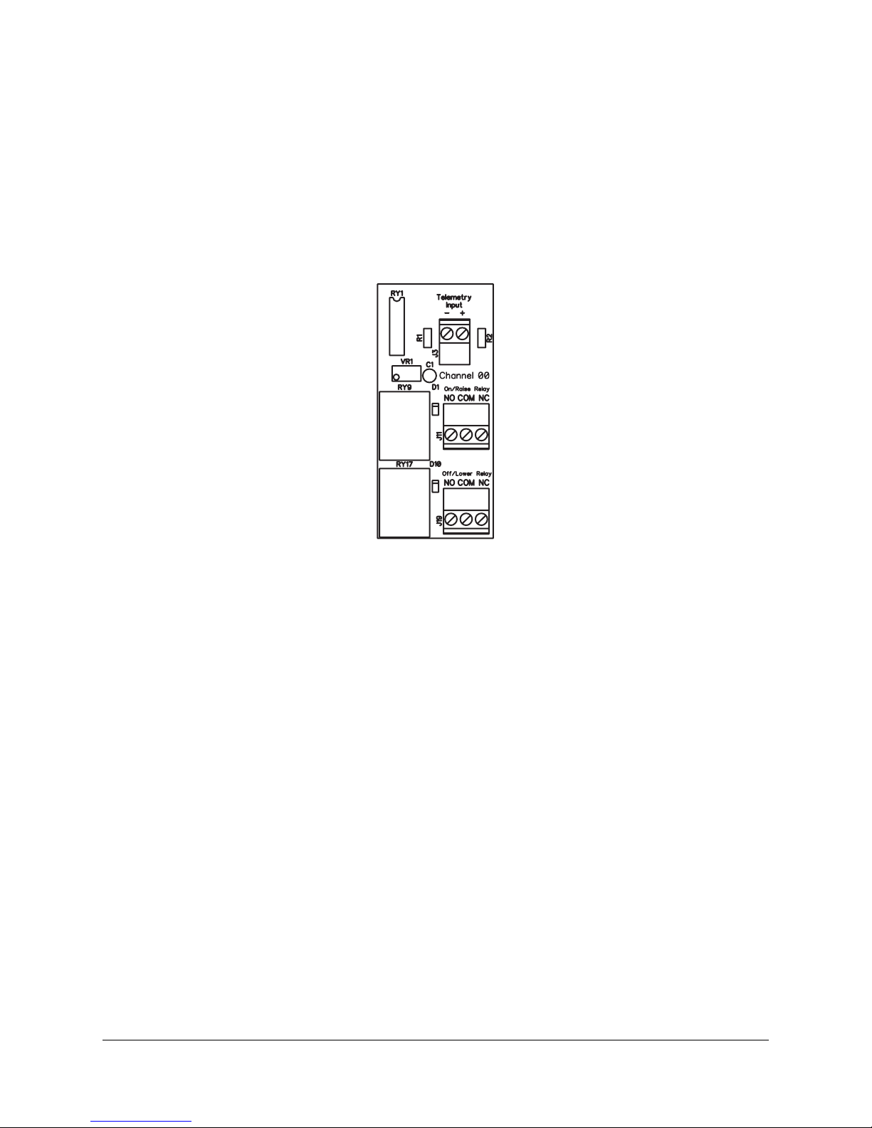
3.2.6 RP-8 Channel Identification
The front of the RP-8 includes a place to record pertinent data regarding each channel. Remember, the channels
read in the correct order from the back of the panel when wiring. Channels read right to left as viewed from the front
of the panel—the lowest channel number is on the far right.
Ch. 00Ch. 07 Ch. 01Ch. 02Ch. 03Ch. 04Ch. 05Ch. 06
Figure 3.5; Order of RP-8 channels as viewed from front
It is often desirable to write the channel number in the space indicated as well as any other information pertinent to
that channel. A grease pencil works well for this task. A permanent marker can be used but it will be difficult to
remove the ink without damaging the painted panel if it becomes necessary to do so.

RFC-1 Installation page 3.6
3.2.7 Telephone and Telephone Line Connection
The RFC-1 should be connected to a standard (POTS) telephone line with the modular (RJ11C) jack on the rear
panel labeled "Line". A telephone cable is supplied with the RFC-1 for this purpose. A telephone may be connected
to the jack labeled "Phone". This telephone will be used to control the RFC-1 locally (on-site) and will function
normally when the RFC-1 is not online.
Line Phone
Power
Sine Systems, inc
Relay Panels
Remote Facilities Controller model RFC-1/B • Sine Systems, Inc. • Nashville,Tennessee
Figure 3.6; RFC-1/B rear panel I/O connectors
3.2.8 Power Supply
Power to operate the RFC-1 and up to eight RP-8 panels is supplied by a 12 volt AC wall-plug transformer that is
supplied with the RFC-1. This transformer is designed for 120 volts AC at 50-60 Hz and is rated at 1 amp. The leads
of this transformer should be stripped and connected to the screw terminal connector marked “12 VAC” on the RP-8.
If more than one RP-8 is used, connect to any one of the RP-8 panels. If the supplied transformer has a connector
on the end of the power cord, simply cut the connector off and discard it.
Figure 3.7; RP-8 Power and I/O connections
In installations where 120 volts AC is not available, the RFC-1 may be powered by any source delivering 12.0 to 14.2
volts AC at 50-60 Hz or 16 to 18 volts DC. The RFC-1 draws a maximum of approximately 0.50 amps when a control
relay is engaged. A 12.6-volt filament transformer makes a good substitute power source. The power source must
be floating. Neither side of the power source should be connected to ground (earth) nor should the power source be
connected to any other equipment. Failure to observe this precaution will result in inaccurate telemetry indications.

RFC-1 Installation page 3.7
3.3 Telemetry Source Inputs
Telemetry samples may be elevated several hundred volts above ground on some equipment.
Permanent damage may occur to the RFC-1 and/or external equipment if a high voltage telemetry
source is connected to the RP-8! Failure to observe this warning may also cause injury to the
installer or other personnel.
Telemetry inputs are located across the top of the RP-8 panel through the 8 two conductor terminal blocks marked
“Telemetry”. The channels are identified as “00” through “07”. In situations where more than one RP-8 is used,
channel numbers increase by 8 on each successive relay panel.
The RFC-1 will accept either a positive or negative DC voltage source as a telemetry input. One volt DC is the
minimum voltage required for a full-scale reading. A lower input voltage can be used but the maximum reading will
not reach full scale. Low sample voltages can be calibrated initially but changing readings will have steps instead of
being smooth and continuous.
Telemetry samples over 5 volts may be used but calibration accuracy suffers on analog readings. Telemetry sample
voltage is less critical for status on/off channels. Samples for status channels may be up to 10 volts DC. Telemetry
sample voltage should never exceed 16 volts DC.
Excessive telemetry sample voltage reduces the useful range of the 22 turn calibration pots to the last few turns. The
result is an overly sensitive calibration that is “touchy”—a small change of the calibration pot causes a large change
in the telemetry reading.
Telemetry samples that are significantly over 5 volts should be reduced with an external attenuator. One solution is
to add a 2.2 KΩshunt resistor across the telemetry input terminals and a series resistor in the telemetry sample. The
series resistor should be about 2200 Ωper volt in excess of two volts. For example, to attenuate a telemetry voltage
of 10 volts, use a 2.2 KΩshunt resistor and an 18 KΩseries resistor. The values are not critical.
The telemetry terminal blocks are polarity specific. Connect the positive (high) side of the telemetry source to the “+”
terminal and the negative (low) side to the “-” terminal. Either side may be ground referenced if necessary.
Telemetry sources may be offset from ground up to 30 volts.
Shielded wire is not normally necessary for short runs to the telemetry inputs since a considerable amount of RFI
filtering is built into the RFC-1. However, long cable runs or lines from AM sampling loops may contain a very large
amount of RF energy which can cause telemetry linearity or other problems. Excessive RF energy can burn the
telemetry input components on the RP-8. This problem can usually be eliminated by inserting 2.5 mH chokes in
series with each telemetry lead.
It makes sense for the telemetry and control on a channel to be related. If the relays on a channel are wired to
control transmitter power, then the telemetry sample on that channel should indicate transmitter power too.
There is no internal hardware connection between the telemetry input and the control I/O. It is entirely possible for a
single channel to control a function that is completely unrelated to the telemetry. System operation is not intuitive in
such a case but the RFC-1 allows this.
Channel readings do not change just because a control function is given. A sample voltage is required to indicate
any change of state. In other words, if you activate the control relay on a channel to turn on a device and there is no
telemetry sample from that device to indicate that the device turned on, the channel reading will still be “status off”.

RFC-1 Installation page 3.8
3.3.1 Analog Readings
Any telemetry channel can be a status channel on the RFC-1. Explained briefly, the RFC-1 has the capability to read
telemetry over a range of 0000 to 2040. If the reading is:
•Between 0003 and 2039 the telemetry is spoken as four digits
•Lower than 0003 the words "status off" are spoken
•Higher than 2037 the words "status on" are spoken
Thus, any channel can act as either an analog input or a status channel with no specific programming changes. A
voltage must be applied to a telemetry input indicate a change of status. The voltage will be interpreted as a logic
level signal by the RFC-1 using the rules listed above.
3.3.2 Status Readings
The diagram below shows how to wire a telemetry input for a status output. When the external contact is closed, the
channel will read "status on" and when the contacts are open the telemetry will read "status off".
Figure 3.8; Typical wiring for a normally open status channel
The power supply shown in the illustration can be a simple wall-plug transformer that supplies anywhere from 6 to 12
volts DC. A single power supply can be used for many status contacts. The external 1 KΩresistor is added to
discharge the input smoothing capacitor on the RP-8 more quickly. Without this resistor it takes about 5 seconds to
reach a “status off” reading after the external contacts open. Adjust the telemetry calibration pot so that the system
reads "status on" when the external contact closes.
This example illustrates one method of generating a status indication. There are many others. For example, to read
a closed contact as "status off", connect the voltage source through a 1 KΩresistor to the positive telemetry terminal
and bridge the contact across the positive and negative telemetry terminals. A closed contact will short the voltage
and produce a "status off" indication.
Figure 3.9; Typical wiring for a normally closed status channel

RFC-1 Installation page 3.9
In some cases it is necessary to use an externally generated voltage to indicate status. Suppose, for example, that a
large AC contactor that does not have auxiliary contacts is to be metered. A small step-down transformer can be
placed across the coil of the contactor to generate a low voltage AC sample. The low voltage AC can then be routed
through a series diode and resistor (approximately 1 KΩ) to the telemetry input. The 10 µF capacitor on the RP-8
should provide sufficient filtering. Do not apply more than 16 volts DC to the telemetry input terminals!
3.3.3 Calibrating Telemetry Readings
Calibrating the telemetry inputs requires basic operational skills with the RFC-1 in local mode. Skip ahead and read
the section that covers operation from the local phone if you have no previous experience with the RFC-1.
Calibrating the telemetry inputs involves adjusting the channel readings so that they correspond to the readings given
from front panel meters. The process is to adjust the calibration pot just behind the front panel for a given channel
while checking the value with the local phone. Tweak the calibration pot until the RFC-1 reads the same reading that
is shown on the corresponding front channel meter. Channels read right to left as viewed from the front of the
panel—the lowest channel number is on the far right. Make sure that you adjust the correct pot for the channel that
you are calibrating.
Figure 3.10; Telemetry calibration point
The calibration pots are 22-turn trimmer resistors that allow precise adjustment. The pots have a clutch at each
extreme to protect the internal mechanism from traveling too far but the pot will turn indefinitely. It does make a faint
clicking sound at each end of travel.
As you adjust the pot, the RFC-1 will read new values automatically if the change is very large. However, as you
close in on the proper value, you will need to reselect the channel to get an updated reading. Take advantage of as
much of the scale as possible. If the normal reading is 100, calibrate the channel to 1000. This is still well within the
upper limit of 2040 and offers much higher resolution than if the channel was calibrated to 0100.
From the factory, the RFC-1 will read a four-digit value between 0003 and 2039 with no decimal point. Programming
options include different scales, a decimal point, unit words and lead zero suppression. The Advanced Operation
section of this manual contains more information.

RFC-1 Installation page 3.10
3.4 Control Outputs
While the control relay contacts are rated for 120 volts AC, only low voltage AC or DC sources
should be connected to the RP-8. The large number of exposed terminals on this panel could
result in a hazardous condition to the installer or other personnel if high voltage were present.
Each RP-8 relay panel has eight “On/Raise” relay contacts and eight “Off/Lower” relay contacts. The output relay
contacts are form C (SPDT), floating, and rated at 120 volts AC, 5 amperes resistive, 2 amperes inductive. Both
normally open (NO) and normally closed (NC) contacts are available on the three conductor terminal block for each
relay.
The control relays on the RP-8 are momentary relays that operate as long as the control commands (* or #) are sent
to the RFC-1. An external latching relay must be used if maintained outputs are required. The appropriate output
relay of the RP-8 can be used to provide a control signal to the latching relay. Electrical or mechanical latching relays
can be used but electrical latching relays may chatter if there is a power supply glitch.
3.5 Telephone Interface
The RFC-1 should be connected to an ordinary (POTS) telephone line. In some cases a telephone line is either not
available or is prohibitively expensive. There are several alternatives to a regular telephone line that are compatible
with the RFC-1.
3.5.1 Cellular Telephone with an RJ-11 Adapter
It is possible to connect a cellular telephone to the RFC-1 in place of a telephone line. Some phone manufacturers
offer docking-station devices that equip an off-the-shelf cellular telephone with a standard RJ-11 jack. There are also
stand-alone devices that combine the radio and emulation hardware in one device. Both types of devices emulate a
standard telephone line including dial tone, ring voltage and battery.
Most devices of this type operate better in a typical transmitter environment with an external antenna and a constant
power supply. Some manufacturers offer these items as part of their product line. There are also many aftermarket
devices that may be useful. The best approach is to discuss your needs with your supplier to find a solution that
meets the needs of the specific site.
Most devices that emulate a telephone line generate a functional but non-standard ring signal on incoming calls. The
RFC-1 has a firmware adjustment to help it recognize the non-standard ring signal. The Advanced Programming
section of the RFC-1 documentation provides details on making this adjustment.
3.5.2 Fixed Location Cellular Telephones
An alternative to using a mobile cell phone with an RJ-11 adapter is to use a phone designed specifically for fixed
locations. These devices combine the wireless radio and line emulation hardware into one device.
Fixed location devices tend to cost more than docking stations but they are typically more flexible and more robust
then their low-cost counterparts. For instance, most fixed-location devices easily support an external antenna.
This manual suits for next models
1
Table of contents
Popular Remote Control manuals by other brands

Universal Electronics
Universal Electronics Apple TV Remote for Video Service Providers user manual

Tripp Lite
Tripp Lite Keyspan URM-15T quick start guide

Comfortaire
Comfortaire B-SMA owner's manual

WhisperPower
WhisperPower WP-BC Instructions for use

Icom
Icom IC-RM2 instruction manual

Fly Sky
Fly Sky FS-T6 instruction manual

Microtech
Microtech e-Trap quick start guide

Contec
Contec CheckMate IV RT-U49A Programming and operating instructions

Contro l4
Contro l4 C4-SR260 manual

Sky Master
Sky Master Universal Remote Control user manual

mundoclima
mundoclima KJRH-120K/BMKO-E Owners & installation manual

One Forall
One Forall URC-7140 user manual


