Sinee EM500 User manual

EM500 Open-Loop Vector Control Inverter User Manual
1
Preface
Thank you for purchasing EM500 series inverter.
Document No.: 31010076
Issue Date: 2017-03
Version: 102
EM500 inverter is an open-loop vector control inverter that supports: 3-phase AC
induction motor and permanent magnet synchronous motor; multiple internationally
leading drive control technologies, including improved vectored VF control technology
(VVF) and sensorless vector control technology (SVC); speed and torque control; I/O
expansion card, communication bus expansion card and special function expansion card.
EM500 dedicates to any application, so it can be applied to nearly all open-loop
control applications, for example fan, water pump (water supply under constant pressure),
air compressor, winding and unwinding function, and direct wire-drawing machine. For
high-precision closed loop application, please select EM600.
Main features:
Built-in DC reactor starting from 11kW, reducing input current distortion,
improving power factor and enhancing reliability of the product;
High torque control precision: SVC/±8% rated torque;
Wide speed regulation range and high control precision: VF/1:50, SVC/1:200 and
±0.2% rated speed;
Loading capacity at low frequency: VF/1Hz/150% and SVC/0.25Hz/150%;
Multiple types of guarantees: Overvoltage stall, rapid current limit, overload
protection, overheating protection, off-load protection, overspeed protection, etc.;
Support I/O expansion: 4 numeric inputs, 1 numeric output, and one -10V - 10V
voltage input;
Support communication bus expansion and realize various industrial networking:
485 bus, Profibus-DP network, CANopen network and DeviceNet network;
Support special function expansion: constant pressure water supply and so on.
Please read this manual carefully before using EM500 and keep it properly.
Before connecting inverter and a motor for the first time, please select proper
motor type (induction motor or synchronous motor) and configure motor nameplate
parameters including rated power, rated voltage, rated current, rated frequency,

EM500 Open-Loop Vector Control Inverter User Manual
2
rated rotation speed, motor connection and rated power factor.
Since SINEE is committed to the development and improvement of products and
product documents, this manual will be updated without notice.
Latest updates and additional information are available at www.sineedrive.com.
EM500 Open-Loop Vector Control Inverter User Manual
3
Safety Information
In this manual, there are two types of safety information.
Danger: The label indicates that a failure to follow instructions can result in
serious injury or even death.
Caution: The label indicates that a failure to follow instructions can result in
moderate or slight injury and device damage.
Please read this chapter carefully before system installation, debugging and
maintenance and always follow the safety precautions below during operation. SINEE
will not undertake any damage or loss caused by a failure to follow the instructions.
Safety Precautions
Before Installation:
Danger
1. Do not install inverter if its package is wetted or any its component is missing or broken.
2. Do not install inverter if the label information on its package is not identical to that on
inverter.
Caution
1. Be careful when carrying or transporting inverter so as to avoid damage!
2. Do not use inverter if it is damaged or any component is missing so as to avoid injury!
3. Do not touch the parts of control system with bare hands so as to avoid ESD!
During Installation:
Danger

EM500 Open-Loop Vector Control Inverter User Manual
4
1. Installation base shall be metal or other non-flammable material so as to prevent fire
risk.
2. Do not unscrew fixing bolts, especially bolts with red mark.
Caution
1. Ensure that no cable strips or screws are dropped into inverter so as to avoid damage to
inverter.
2. Install inverter at a place with less vibration and no direct sunlight.
3. Consider the installation space for cooling purpose when inverter is installed in a closed
cabinet or space.
Wiring:
Danger
1、Wiring must be performed by authorized and qualified personnel so as to avoid
unexpected accidents.
2、A circuit breaker must be installed between inverter and the mains so as to prevent fire
risk.
3、Ensure that power is off before wiring, and ground inverter in accordance with the
applicable wiring standard so as to avoid electric shock.
4、Grounding terminal must be grounded reliably so as to avoid electric shock and fire
risk.
Danger
1、Never connect input power supply cable to output terminals U, V or W of inverter. Pay
attention to terminal symbols and connect to the terminals correctly so as to prevent risks of
damaging inverter.
2、Be sure that wiring meets EMC requirements and local safety standards. Cable should
be in recommended sizes so as to prevent accident risk.
3、Do not connect braking resistor to DC bus terminals + and – so as to prevent fire risk.
4、Tighten terminals with a screwdriver of specified torque so as to prevent fire risk.
5、Do not connect a phase-shifting capacitor or an LC/RC noise filter to output circuits.
6、Do not connect a solenoid switch or an electromagnetic contactor to output circuits.
Otherwise, it will trigger the action of the overcurrent protection circuit or even damage the
internal parts of inverter.
7、Do not disconnect internal cable of inverter, or else this can possibly damage the
internal parts of inverter.
Caution
1. Ensure the distribution lines accord to EMC requirements and the local area's safety
EM500 Open-Loop Vector Control Inverter User Manual
5
standards. The using wire size refers to the preferred recommendation. Otherwise, an
accident may occur!
2. Never connect the braking resistor directly between the DC bus and the terminals.
Otherwise cause a fire!
3. Tighten the terminal with the specified torque screwdriver, otherwise there is the danger
of fire.
4. Do not connect the phase-shift capacitor LC / RC noise filter to the output circuit
5. Do not connect the electromagnetic switch or electromagnetic contactor to the output
circuit. Otherwise, the inverter over-current protection circuit is activated when severe, can
cause damage to the inverter.
6. Do not disassemble the connecting cable inside the inverter. Otherwise, the inverter may
be damaged.
Before Power-on:
Danger
1、Verify that input voltage is identical to the rated voltage of inverter, input terminals R,
S and T and output terminals U, V or W are correctly connected, there are no short circuit
phenomena for the wiring of inverter and its peripheral circuits, and all wires are in good
connection. Otherwise, this may result in inverter damage.
2、Never perform voltage withstanding test on inverter, because it has been done at the
factory. Otherwise, this may result in accident.
Caution
1、The front cover of inverter must be closed before inverter is powered on. Otherwise, it
may result in an electric shock.
2、The wiring of all peripherals must be conducted in accordance with the guidance of
this manual. Otherwise, it may result in an electric hazard.
After Power-on:
Danger
1. Do not touch inverter or its peripheral circuits with wet hands to avoid the electric
shock.
2. If the indicator is off or the keypad does not display any information after power-on,
EM500 Open-Loop Vector Control Inverter User Manual
6
please cut off the power supply immediately. Never touch any terminal of R, S or T of
inverter or the connecting terminals with hands or a screw driver, or else an electric shock
accident may occur. Contact our customer service personnel immediately after cutting off
the power.
3. After being powered on, inverter will automatically check the safety of the external
strong circuit automatically. Therefore, do not touch wiring terminal U, V or W of inverter
or the wiring terminal of the motor with bare hands, otherwise it will result in electric
shock.
Caution
1、If you need to check parameter settings, be careful of personal safety when the motor
is running so as to avoid accidents.
2、Do not change default parameter setting without approval to avoid damage.
During Operation:
Danger
1、Never touch cooling fan, heat sink or discharge resistor with bare hands for checking
temperature, which may result in burning!
2、Only qualified technicians are allowed to detect signal during operation so as to
prevent personal injury or device damage.
Caution
1、Prevent any foreign items from being dropped into the device during operation, so as
to avoid damage to the device.
2、Do not control the start/stop of inverter by ON/OFF of the contactor so as to avoid
damage to the device.
Maintenance:
Danger
1、Maintain and inspect the device only after inverter is powered off for at least 10
minutes to avoid electric shock.
2、Maintain and inspect inverter only after its main circuit is powered off and CHARGE
indicator is off. Otherwise, the residual electric charge of capacitor may result in personal

EM500 Open-Loop Vector Control Inverter User Manual
7
injury.
3、Maintenance and inspection can be performed by well-trained technicians only, so as
to avoid personal injury or device damage.
4、Parameter setting is required if inverter has been replaced. Plug-in & plug-out should
be performed after power-off.
5、For synchronous motor, it will generate power when in rotation, please wait for at least
10 minutes after it stops rotating, and then disconnect the motor from the inverter,
otherwise there is risk of electric shock.
6、
Attentions
Motor Insulation Inspection
Motor insulation inspection shall be performed before using a motor for the first time or
left unused for some time or during routine inspection, in order to avoid damaging
inverter due to failure of insulation performance of motor winding. Make sure to
disconnect motor cable from inverter during inspection; 500V megohmmeter is
recommended. The obtained insulation resistance from test shall not be lower than 5MΩ.
Motor Thermal Protection
If the selected motor does not match with inverter in rated capacity, especially when its
rated power is lower than that of inverter, be sure to adjust motor protection parameters of
inverter or install a thermal relay in front of the motor to protect the motor.
Operation at Power frequency
Output frequency of inverter ranges from 0.00 Hz to 600.00 Hz. To use inverter at over
50.00 Hz, please consider the bearing capacity of mechanical device.
Motor Heat and Noise
Since output voltage of inverter presents a PWM waveform along with some harmonic
waves, the temperature rise, noise and vibration of motor would increase a little in
comparison with the running under power frequency.
Varistor or Power Factor Improvement Capacitor on Inverter Output
Inverter outputs PWM wave. Do not use inverter, if a power factor improvement
capacitor or a lightning varistor is on output side, which may easily result in transient
overcurrent of inverter, or even damage inverter.
Beyond Rated Voltage
Do not use EM500 inverter outside the operating voltage range specified in this manual,
which may easily damage its internal parts. If you have to do so, install a voltage rise or
reduction device for transformation.

EM500 Open-Loop Vector Control Inverter User Manual
8
Surge Protection
A surge protection device is installed in inverter to prevent it from induction lightning
stroke on a certain degree. Additional protection devices are required in front of inverter
in the places where thunder and lightning occur frequently.
Altitude and Derating
When inverter is used in an area at an altitude of over 1,000m, the cooling effect will
degrade, so it must be derated. For details, please consult SINEE.
Attentions at Inverter Scrapping
Burning the electrolytic capacitors of the mains and PCB may result in explosion and
burning plastic parts may generate toxic gas. Please handle them as industrial wastes
when inverter is scrapped.

EM500 Open-Loop Vector Control Inverter User Manual
9
CONTENTS
PREFACE....................................................................................................... 1
SAFETY PRECAUTIONS..................................................................................................... 3
ATTENTIONS....................................................................................................................7
1. OVERVIEW..............................................................................................14
1.1 EM500 MODEL LIST AND TECHNICAL SPECIFICATIONS.......................................... 14
1.2 EM500 OPERATION STATUS.................................................................................... 17
1.3 DESCRIPTION OF PARTS OF EM500 INVERTER......................................................... 22
2. INSTALLATION......................................................................................24
2.1 PRODUCT VERIFICATION.......................................................................................... 24
2.2 OVERALL AND INSTALLATION DIMENSIONS.............................................................25
2.3 CONSIDERATIONS FOR INSTALLATION SITE..............................................................29
2.4 INSTALLATION DIRECTION AND SPACE....................................................................30
2.5 ASSEMBLY AND DISASSEMBLY OF KEYPAD............................................................. 31
2.6 FLUSH MOUNTING................................................................................................... 32
3. WIRING.................................................................................................... 36
3.1 CONNECTION TO PERIPHERALS................................................................................ 36
3.2 WIRING MAIN CIRCUIT TERMINALS.........................................................................37
3.3 WIRING CONTROL CIRCUIT TERMINALS...................................................................48
3.4 EXTENDING KEYPAD WIRE...................................................................................... 60
3.5 WIRING VERIFICATION............................................................................................. 60
4. KEYPAD OPERATION.......................................................................... 61
4.1 KEYPAD FUNCTION.................................................................................................. 61
4.2 LED KEYPAD OPERATION MODE............................................................................ 63
4.3 FAULT MONITORING................................................................................................ 69
4.4 OPERATION MONITORING........................................................................................ 70

EM500 Open-Loop Vector Control Inverter User Manual
10
4.5 PARAMETER COPY................................................................................................... 70
4.6 FUNCTION OF M.K................................................................................................... 71
4.7 RUN/STOP.................................................................................................................71
5. TRIAL OPERATION...............................................................................72
5.1 TRIAL OPERATION PROCEDURE............................................................................... 72
5.2 ATTENTIONS FOR TRIAL OPERATION........................................................................74
6. FUNCTION CODE TABLE....................................................................76
6.1 PARAMETER DESCRIPTION....................................................................................... 76
6.2 FUNCTION PARAMETER TABLE.................................................................................78
7. PARAMETER DESCRIPTION............................................................154
7.1 F00 GROUP: GENERAL PARAMETER......................................................................154
7.2 F01 GROUP: MOTOR 1 PARAMETER...................................................................... 174
7.3 F02 GROUP: INPUT TERMINAL PARAMETER..........................................................179
7.4 F03 GROUP: OUTPUT TERMINAL FUNCTION PARAMETER.....................................196
7.5 F04 GROUP: START/STOP CONTROL PARAMETER.................................................208
7.6 F05 GROUP: VF CONTROL PARAMETER................................................................215
7.7 F06 GROUP: VECTOR CONTROL PARAMETER....................................................... 221
7.8 F07 GROUP: FAULT PROTECTION PARAMETER..................................................... 229
7.9 F08 GROUP: PRESET SPEED AND SIMPLE PLC PARAMETER................................. 237
7.10 F09 GROUP: PID FUNCTION PARAMETER........................................................... 244
7.11 F10 GROUP: COMMUNICATION FUNCTION PARAMETER...................................... 257
7.12 F11 GROUP: USER-DEFINED PARAMETER........................................................... 266
7.13 F12 GROUP: KEYPAD AND DISPLAY PARAMETER................................................ 268
7.14 F13 GROUP: TORQUE CONTROL PARAMETER...................................................... 278
7.15 F14 GROUP: MOTOR 2 PARAMETER.................................................................... 284
7.16 F15 GROUP: AUXILIARY FUNCTION.................................................................... 285
7.17 F16 GROUP: USER DEFINED FUNCTION PARAMETER..........................................298
7.18 F17 GROUP: VIRTUAL I/O FUNCTION PARAMETER.............................................305

EM500 Open-Loop Vector Control Inverter User Manual
11
7.19 F18 GROUP: MONITORING PARAMETER.............................................................. 310
7.20 F19 GROUP: FAULT RECORD PARAMETER.......................................................... 314
7.21 F25 APPLICATION OF WATER SUPPLY BASIC GROUPS.......................................317
7.22 F26 APPLICATION OF WATER SUPPLY ADVANCED GROUP.....................................327
7.23 F27 WINDING ROLLING APPLICATION..................................................................330
7.24 F28 AIR COMPRESSOR APPLICATION................................................................... 347
8. MOTOR PARAMETER AUTOTUNING............................................ 362
8.1 MOTOR PARAMETER AUTOTUNING........................................................................ 362
8.2 PRECAUTIONS BEFORE AUTOTUNING.....................................................................362
8.3 STEPS OF AUTOTUNING.......................................................................................... 363
9. TROUBLESHOOTING.........................................................................365
9.1 FAULTS...................................................................................................................365
9.2 WARNING ANALYSIS.............................................................................................. 373
9.3 FAULT ANALYSIS................................................................................................... 375
10. MAINTENANCE AND INSPECTION..............................................379
10.1 ROUTINE MAINTENANCE AND INSPECTION OF INVERTER.....................................379
10.2 WARRANTY INSTRUCTION FOR INVERTER.............................................................381
11. OPTIONS.............................................................................................. 382
11.1 BRAKING RESISTOR..............................................................................................382
11.2 BRAKING UNIT.....................................................................................................383
11.3 OPTIONS OF CABLE.............................................................................................. 383
11.4 OPTION CARD.......................................................................................................384
11.5 BASE.................................................................................................................... 385
11.6 UPPER MOUNTING HOLE......................................................................................388
11.7 COPPER ROW FOR INCOMING AND OUTGOING CABLE SWITCHOVER...................389
12. MODBUS COMMUNICATION PROTOCOL.................................391
12.1 APPLICATION SCOPE............................................................................................ 391

EM500 Open-Loop Vector Control Inverter User Manual
12
12.2 PHYSICAL INTERFACE.......................................................................................... 391
12.3 PROTOCOL FORMAT............................................................................................. 392
12.4 PROTOCOL DESCRIPTION..................................................................................... 414
12.5 EXAMPLE............................................................................................................. 417
13. CANSINEE COMMUNICATION PROTOCOL............................. 422
13.1 APPLICATION SCOPE............................................................................................ 422
13.2 PHYSICAL INTERFACES.........................................................................................422
13.3 PROTOCOL FORMAT............................................................................................. 423
13.4 BROADCAST MESSAGES....................................................................................... 431
13.5 ABNORMAL INFORMATION RESPONSE.................................................................. 432
13.6 ILLUSTRATE..........................................................................................................433
APPENDIX I. MULTI-FUNCTIONAL IO EXPANSION CARD
(EC-IO-A1)..................................................................................................438
I.1 GENERAL............................................................................................................... 438
I.2 INSTALLATION INSTRUCTIONS..............................................................................438
I.3 EXPANSION TERMINAL FUNCTION....................................................................... 439
APPENDIX II MULTI-FUNCTIONAL IO EXPANSION CARD 3
(EC-IO-A3)..................................................................................................441
II.1 GENERAL............................................................................................................. 441
II.2 INSTALLATION INSTRUCTIONS............................................................................ 441
II.3 EXPANSION TERMINAL FUNCTION......................................................................442
APPENDIX III PROFIBUS-DP EXPANSION CARD (EC-CM-P1)...443
III.1 GENERAL............................................................................................................443
III.2 INSTALLATION INSTRUCTIONS...........................................................................443
III.3 EXPANSION TERMINAL FUNCTION.................................................................... 444
APPENDIX IV CANOPEN EXPANSION CARD (EC-CM-C1)..........446
IV.1 GENERAL.............................................................................................................446

EM500 Open-Loop Vector Control Inverter User Manual
13
IV.2 INSTALLATION INSTRUCTIONS........................................................................... 446
IV.3 EXPANSION TERMINAL FUNCTION.....................................................................447
APPENDIX V DEVICENET EXPANSION CARD (EC-CM-D1)........449
V.1 GENERAL.............................................................................................................. 449
V.2 INSTALLATION INSTRUCTIONS.............................................................................449
V.3 EXPANSION TERMINAL FUNCTION...................................................................... 450
APPENDIX ⅥAIR COMPRESSOR EXPANSION CARD
(EC-CM-D1)................................................................................................453
Ⅵ.1 GENERAL.............................................................................................................453
Ⅵ.2 INSTALLATION INSTRUCTIONS........................................................................... 453
Ⅵ.3 EXPANSION TERMINAL FUNCTION.....................................................................454
APPENDIX ⅦCLOCK EXPANSION CARD (EC-TM-A1)..............456
Ⅶ.1 GENERAL.............................................................................................................456
Ⅶ.2 INSTALLATION INSTRUCTIONS........................................................................... 456
Ⅶ.3 EXPANSION TERMINAL FUNCTION....................................................................... 457
APPENDIX ⅧAPPENDIX VII. PHASE SEQUENCE EXPANSION
CARD (EC-PSP-A1).................................................................................. 458
Ⅷ.1 GENERAL.............................................................................................................458
Ⅷ.2 INSTALLATION INSTRUCTIONS........................................................................... 458
Ⅷ.3 EXPANSION TERMINAL FUNCTION....................................................................... 459

EM500 Open-Loop Vector Control Inverter User Manual
14
1. Overview
1.1 EM500 Model List and Technical Specifications
Rated voltage: 3-phase, 380 - 415VAC, 3-phase or single-phase 220 – 230VAC;
Applicable motor: 3-phase AC induction motor and permanent magnet synchronous
motor, power range: 0.75 - 630kW;
Maximum output voltage is identical to input voltage.
EM500 model and rated output current are shown in Table 1–1.
Table 1-1 EM500 Model List
Rated Voltage
Model
Motor Power (kW)
Rated Output Current (A)
3-phase,
380 - 415V
EM500-0R7G/1R5P-3B
0.75/1.5
2.5/4.2
EM500-1R5G/2R2P-3B
1.5/2.2
4.2/5.6
EM500-2R2G/3R0P-3B
2.2/3.0
5.6/7.2
EM500-4R0G/5R5P-3B
4.0/5.5
9.4/12
EM500-5R5G/7R5P-3B
5.5/7.5
13/17
EM500-7R5G/9R0P-3B
7.5/9
17/20
EM500-011G/015P-3B
11/15
25/32
EM500-015G/018P-3B
15/18.5
32/38
EM500-018G/022P-3B
18.5/22
38/44
EM500-022G/030P-3/3B
22/30
45/59
EM500-030G/037P-3/3B
30/37
60/73
EM500-037G/045P-3/3B
37/45
75/87
EM500-045G/055P-3/3B
45/55
90/106
EM500-055G/075P-3/3B
55/75
110/145
EM500-075G/090P-3/3B
75/90
150/169
EM500-090G/110P-3
90/110
176/208
EM500-110G/132P-3
110/132
210/248
EM500-132G/160P-3
132/160
253/298
EM500-160G/185P-3
160/185
304/350
EM500-185G/200P-3
185/200
357/372
EM500-200G/220P-3
200/220
380/410
EM500-220G/250P-3
220/250
426/456
EM500-250G/280P-3
250/280
465/510
EM500-280G/315P-3
280/315
520/573
EM500-315G/355P-3
315/355
585/640
EM500-355G/400P-3
355/400
650/715

EM500 Open-Loop Vector Control Inverter User Manual
15
EM500-400G/450P-3
400/450
725/810
EM500-450G/500P-3
450/500
820/900
EM500-500G/560P-3
500/560
900/1010
EM500-560G/630P-3
560/630
1010/1140
3-phase,
220~230V
EM500-0R7G/1R5P-2B
0.75/1.5
4.8/8.0
EM500-1R5G/2R2P-2B
1.5/2.2
8.0/10.0
EM500-2R2G/3R0P-2B
2.2/3.0
10.0/13.0
Single-phase
220~230V
EM500-0R7G/1R5P-1B
0.75/1.5
4.8/8.0
EM500-1R5G/2R2P-1B
1.5/2.2
8.0/10.0
EM500-2R2G/3R0P-1B
2.2/3.0
10.0/13.0
★the difference between inverter and motor shall not be more than two power ratings.
Please try to select a motor that matches with inverter in rated current.
EM500 technical specifications are shown in Table 1–2.
Table 1-2 EM500 Technical Specifications
Items
Specifications
Input
Rate Voltage
Range
3-phase 380V-20% - 415V+20%, 3-phase or single-phase 220
– 230VAC; 50 - 60 Hz±5%, voltage unbalance <3%
Output
Maximum
Output Voltage
Maximum output voltage is identical to input voltage.
Rated Output
Current
100% non-stop rated current output
Maximum
Overload
Current
Model G: 150% rated current for 60s, 180% rated current for
10s and 200% rated current for 2s
Model P: 120% rated current for 60s, 150% rated current for
10s and 180% rated current for 2s
Basic
Control
Functions
Control Mode
V/F(VVF) and SVC
Input Mode
Frequency (speed) input and torque input
Start/Stop
Control Mode
Keypad, control terminals (2-wire sequence, 3-wire
sequence) and communication
Frequency
Control Range
0.00 - 600.00 Hz /0.0 – 3000Hz
Input Frequency
Resolution
Numeric input: 0.01 Hz/ 0.1Hz, analog input: 0.1% of
maximum frequency
Governor
Deflection
1: 50 (VVF), 1:200 (SVC)
Speed Control
Accuracy
±0.2% rated synchronous speed
Acceleration/De
celeration Time
0.01-600.00 seconds/0.1 - 6000.0 seconds/1 - 60000 seconds
V/F Features
Rated output voltage: 20% - 100% adjustable; frequency
base: 1 Hz - 600 Hz/3000Hz adjustable

EM500 Open-Loop Vector Control Inverter User Manual
16
Torque Boost
Fixed torque boost curve, customer defined V/F curve scaling
Start Torque
150%/ 1 Hz (VVF), 150%/ 0.25 Hz (SVC)
Torque Control
Accuracy
±8% rated torque (SVC)
AVR
Output voltage remains unchanged basically and input
voltage varies when AVR is active
Automatic
Current Limit
Automatically limit output current to avoid frequently
overcurrent trip.
DC Brake
Brake frequency: 0.01 - Maximum frequency, brake time: 0 -
30S
Brake current: 0% - 100% rated current
Signal Input
Source
Communication, preset speed, analog, high-speed impulse
Function
of Input
and Output
Reference
Power Supply
10V/20mA
Terminal
Control Power
Supply
24V/200mA
Numeric Input
Terminal
7 (standard X1 - X7) + 4 (expansion card X8 - X11) numeric
multi-functional input terminals:
X7 can be selected as high-speed impulse input terminal
(F02.06=35/38/40);
X1 - X6 and X8 - X11 (10 in total) can be used as common
digital input terminals.
Analog Input
Terminal
3 (standard AI1 -AI3) + 1 (expansion card AI4) analog
input terminals:
1 (AI1) voltage source 0 - 10 input;
2 (AI2/AI3) voltage source 0 - 10V inputs or current
source 0 - 20mA input;
1 (AI4) voltage source -10V - 10V input
Numeric Output
Terminal
2 (standard Y1/Y2) + 1 (expansion card Y3) OC
multi-functional outputs and 2 (R1: EA/EB/EC and R2:
RA/RB/RC) relay multi-functional outputs.
Maximum output current of OC: 50mA; relay contact
capacity: 250VAC/3A or 30VDC/1A. When the relay works,
EA-EC and RA-RC are on, but EB-EC and RB-RC are off.
Analog Output
Terminal
M1 is with output 0 - 10V only.
M2 is with output 0 - 10V or 0 – 20 mA.
Keypad
Display
LED
LED displays relevant information about inverter.
Parameter Copy
Upload and download parameter setting information of
inverter to realize rapid copy.
Protection
Protection
Short circuit, overcurrent, overvoltage, undervoltage, phase
loss, overload, overheating, overspeed, offload, external fault,
etc.

EM500 Open-Loop Vector Control Inverter User Manual
17
Working
Condition
Installation Site
To be installed indoor with an altitude less than 1,000 meters,
free from dust, corrosive gas and direct sunlight.
Ambient
Temperature
-10℃- +40℃, 20% - 90%RH (no condensation)
Vibration
< 0.5g
Storage
Temperature
-25℃~ +65℃
Installation
Method
Wall mounting, floor mounting (electrical cabinet) and flush
mounting
Protection Degree
IP20/IP21 (450kW and above)
Cooling Method
Forced air cooling
1.2 EM500 Operation Status
1.2.1Operating Status of Inverter
EM500 inverter operating status: Parameter setting status, normal running status,
JOG running status, autotuning status, stop status, JOG stop status and fault status.
Parameter setting status: After it is powered on and initialized and is standby
without a fault or a start-up command, inverter has no output.
Normal running status: Having received an active start command through
keypad, control terminal or communication, inverter drives motor as per the
setting input.
JOG running status: Drives motor at JOG input speed through setting of keypad,
external terminal or communication.
Autotuning status: Set through keypad to autotune the parameters of motor in
stationary or rotational autotuning.
Stop status: When a running command is inactive, output frequency drops to zero
as per set deceleration time.
JOG stop status: When JOG running command is inactive, output frequency
drops to zero as per JOG deceleration time.
Fault status: Status of inverter under protection, and all kinds of faults and
failures.
EM500 Open-Loop Vector Control Inverter User Manual
18
1.2.2Control Modes of Inverter
Control modes of inverter refer to what kind of method is adopted to drive motor at
desired speed or torque. These modes include:
VVF (Vector decoupling based VF control): The steady performance is the same as
that in SVC. Suitable for occasions of low speed change and low speed stability
accuracy and meet the needs of most AC motor drives.
SVC (Sensorless Vector Control): Advanced speed estimate algorithm, no need for
encoder, open loop vector control and high control accuracy.
1.2.3Setting Modes of Inverter
Setting mode of inverter refers to what kind of physical quantity is taken as the
control object when inverter drives motor.
Speed setting mode: Motor speed is taken as the control object;
This mode can be realized by numeric setting, analog input setting, high-speed pulse
input setting, communication setting, digital potentiometer setting, process PID, simple
PLC or preset speed, individually or jointly. In Figure 1-1 to Figure 1-4, various input
modes under the speed setting mode of EM500 are described:
Figure 1-1 Speed Input Mode
As indicated in Figure 1-1, there are mainly three speed setting modes of EM500,
respectively main frequency source A setting (referred to as “Main A” for short),
auxiliary frequency source B setting (referred to as “Auxiliary B” for short) and main &
auxiliary arithmetic setting. The speed setting mode is finalized by simple regulation and

EM500 Open-Loop Vector Control Inverter User Manual
19
limit (upper limit frequency limit, maximum frequency limit, direction limit and
frequency hopping limit). The setting descriptions are given in Figure 1-2 to Figure 1-4.
主频率切换
DI:51~56
0:数字频率给定F00.07
1:AI1*F00.16
2:AI2*F00.16
3:AI3*F00.16
4:AI4*F00.16
5:HDI*F00.16
0
1
2
3
4
5
主
频率源
增益
F00.10
多段速端子
DI:14~11 0
n=1,2,…,15
第n段速
F08.00~F08.14
无
有效 F00.07
AI1
AI2
AI3
HDI(脉冲)
通讯
+
+
6:SCI*F00.16
6
UP/DOWN给定
+
+
Preset speed terminal
DI: 14 - 11
Main frequency
switching
DI: 51 – 56
Disabled
Enabled
Preset speed n
F08.00 – F08.14
Main frequency
source A
F00.04
HDI (pulse)
Communication
0: Numeric frequency setting
F00.07
1: AI1 * F00.16
2: AI2 * F00.16
3: AI3 * F00.16
4: AI4 * F00.16
5: HDI * F00.16
6: SCI * F00.16
UP/DOWN setting
Main
frequency
source gain
F00.10
Figure 1-2 Main Frequency Source A Setting
As indicated in Figure 1-2, when setting main frequency source A, user needs to
consider settings and status of numeric terminals comprehensively. According to terminal
settings, inverter can run at a preset speed or at a speed determined through numeric
setting, analog input, pulse or communication.
If all the numeric terminals are disabled, function code F00.04 is used to set present
channel and is in arithmetic together with UP/DOWN to get the final setting.
Figure 1-3 Auxiliary Frequency Source B Setting

EM500 Open-Loop Vector Control Inverter User Manual
20
As indicated in Figure 1-3, when auxiliary frequency source B is being set, the
setting of F00.05 will be based upon to determine present setting channel. Process PID
and Simple PLC can participate in the setting.
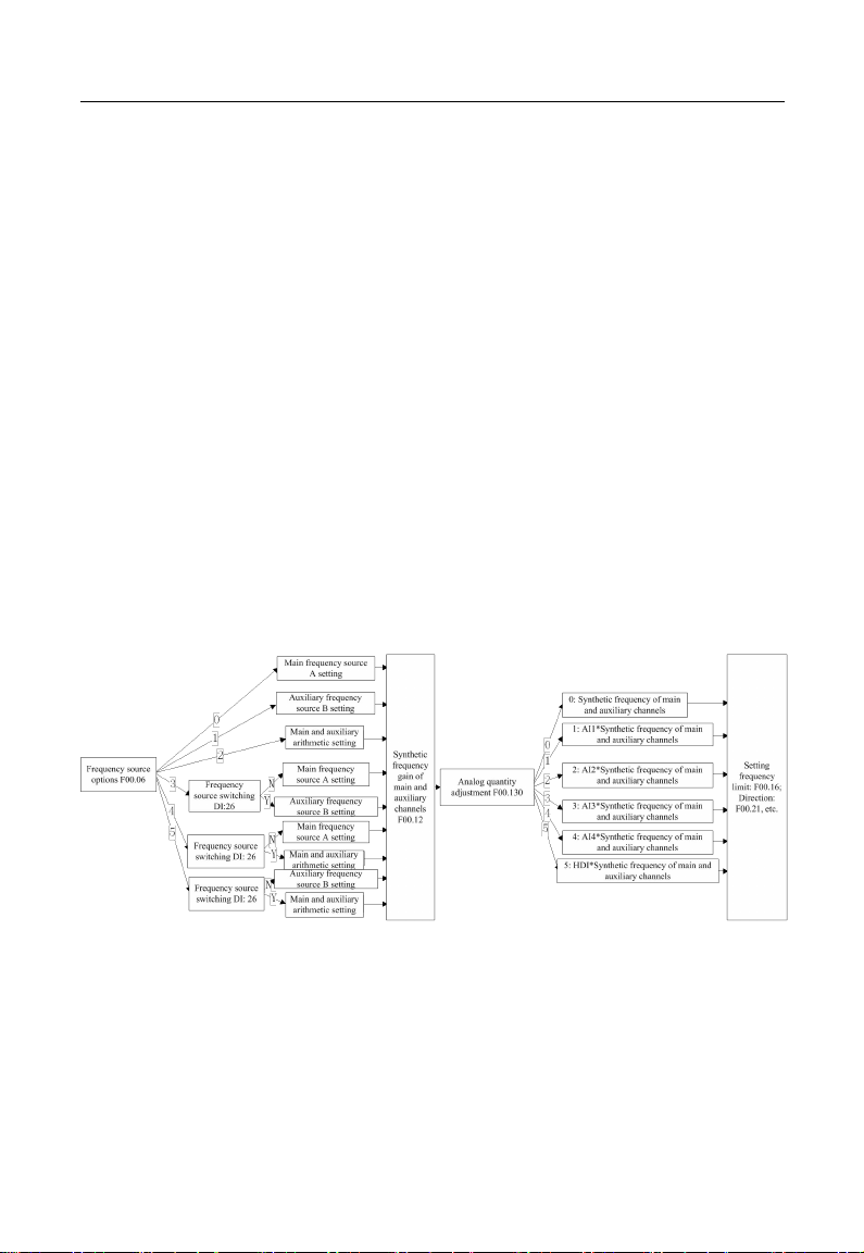
Figure 1-4 Main and Auxiliary Arithmetic Setting
As indicated in Figure 1-4, main and auxiliary arithmetic can be classified into four
categories. At this time, both main and auxiliary settings are enabled.
Torque setting mode: Motor current is taken as the control object.
Torque setting mode can be set by multiple ways, which include numeric setting,
analog input setting, high-speed pulse input setting, communication setting, digital
potentiometer setting and preset torque setting. In Figure 1-5, various input modes for
torque setting of EM500 are described.
Figure 1-5 Torque Setting Mode
Table of contents
Other Sinee Inverter manuals


Popular Inverter manuals by other brands

Berges
Berges ACM-D2 Series operating manual

Resol
Resol DeltaSol AL E Manual for the specialised craftsman

Chelion
Chelion iHome-B5-HD02 Series user manual

SolarEdge
SolarEdge StorEdge SE7600A-USS installation guide

Siemens
Siemens SINAMICS V20 Inverter Compact operating instructions

PNI
PNI L1200W user manual


