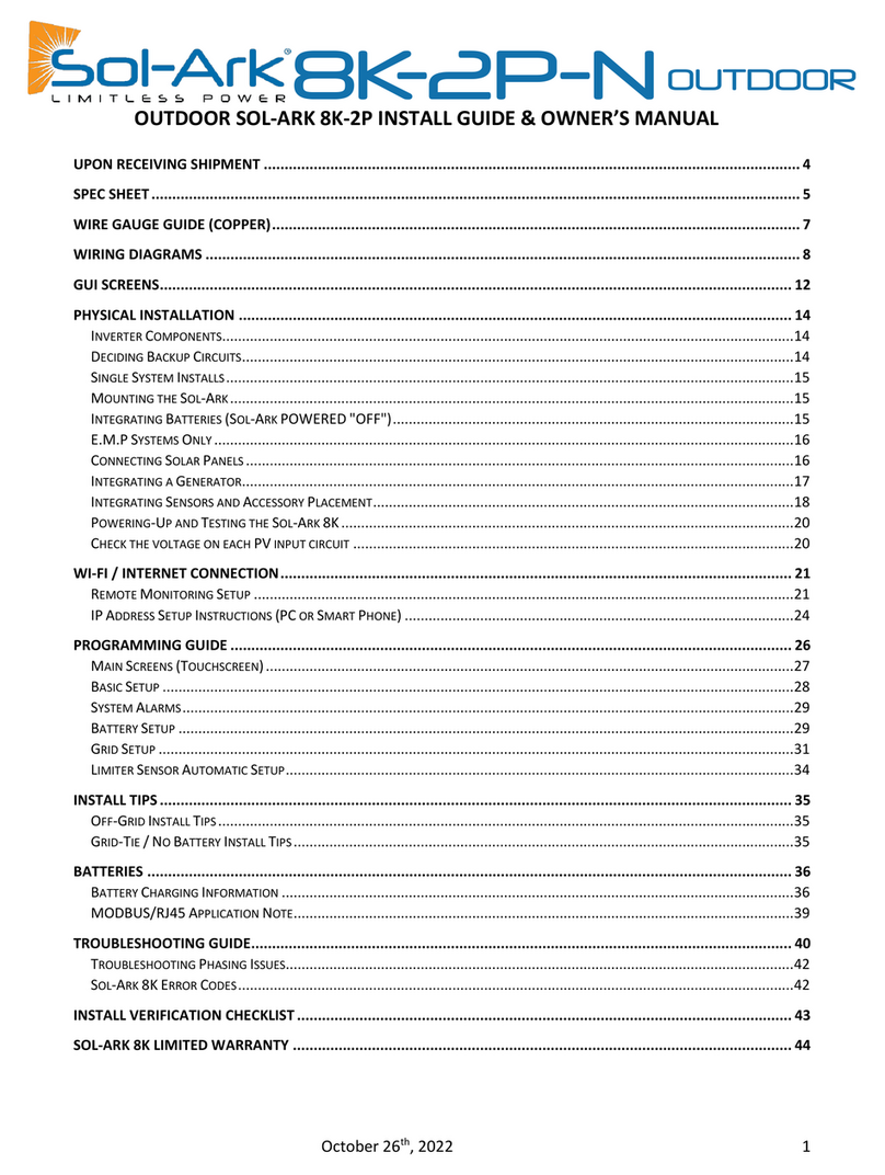
Solark 8K-2P-L User manual

February 7, 2023 1
RESIDENTIAL
INSTALLATION GUIDE USER MANUAL

February 7, 2023 2
READ THE INSTRUCTIONS COMPLETELY
BEFORE OPERATING THE EQUIPMENT.
Check the grid type before turning ON the unit.
Turn ON and program the unit using only batteries.
The unit will be programmed in 120/240V
Split phase at a Frequency of 60Hz, by
default.
Not following the instructions may result in permanent damage to the
equipment.
Warning
STOP

February 7, 2023 3
DISCLAIMER........................................................................................................................................................... 4
WARNING SYMBOLS.............................................................................................................................................. 5
UPON RECEIVING SHIPMENT ................................................................................................................................. 6
WIRE GAUGE GUIDE (COPPER)............................................................................................................................... 9
WIRING DIAGRAMS ............................................................................................................................................. 10
GUI SCREENS........................................................................................................................................................ 18
PHYSICAL INSTALLATION ..................................................................................................................................... 21
INVERTER COMPONENTS................................................................................................................................................21
BACKUP CIRCUITS .........................................................................................................................................................22
MOUNTING THE SOL-ARK..............................................................................................................................................22
INTEGRATING BATTERIES (SOL-ARK 8K-2P-L MUST BE OFF) ................................................................................................24
INTEGRATING A GENERATOR ...........................................................................................................................................26
INTEGRATING SENSORS AND ACCESSORIES .........................................................................................................................28
POWERING-UP AND TESTING THE SOL-ARK .......................................................................................................................29
WI-FI / INTERNET CONNECTION........................................................................................................................... 31
REMOTE MONITORING SETUP ........................................................................................................................................31
IP ADDRESS SETUP (PC OR SMART PHONE)........................................................................................................................32
PROGRAMMING GUIDE ....................................................................................................................................... 39
MAIN SCREEN (TOUCHSCREEN) ......................................................................................................................................40
(1)BASIC SETUP...........................................................................................................................................................42
(2)SYSTEM ALARMS .....................................................................................................................................................43
(3) BATTERY SETUP ......................................................................................................................................................43
(5) GRID SETUP ...........................................................................................................................................................48
LIMITER SENSORS (CT SENSORS).......................................................................................................................... 50
AUTOMATIC S LIMIT SENSORS CONFIGURATION ............................................................................................................51
INSTALLATION TIPS.............................................................................................................................................. 52
OFF-GRID INSTALL TIPS.................................................................................................................................................52
NO BATTERY INSTALL TIPS .............................................................................................................................................52
BATTERIES ........................................................................................................................................................... 53
CHARGE CONTROLLER ...................................................................................................................................................53
NOTE FOR BATTERY COMMUNICATION WITH MODBUS/CANBUS ........................................................................................55
PARALLEL SYSTEMS.............................................................................................................................................. 56
BEFORE ENABLING PARALLEL OPERATIONS .........................................................................................................................56
3PHASE CONFIGURATION IN PARALLEL SYSTEMS.................................................................................................................59
TROUBLESHOOTING GUIDE WITH PHASE SEQUENCE. ............................................................................................................60
TROUBLESHOOTING GUIDE.................................................................................................................................. 61
SOL-ARK 8K-2P-L ERROR CODES ....................................................................................................................................63
INSTALL VERIFICATION CHECKLIST ....................................................................................................................... 64
LIMITED WARRANTY: SOL-ARK 8K-2P-L................................................................................................................ 65
SOL-ARK 8K Installation guide & manual

February 7, 2023 4
Disclaimer
Unless specifically agreed to in writing, Sol-Ark:
(a) Does not warrant the accuracy, sufficiency or suitability of any technical or other information provided in
its manuals or other documentation.
(b) Assumes no responsibility or liability for any loss or damages, whether direct, indirect, consequential or
risk.
Sol-Ark is not responsible for system failure, damage or injury resulting from improper installation of its
products.
Information in this manual is subject to change without notice.
This version is only focused on the inverter labeled as: 8K-2P-L.

February 7, 2023 5
Warning symbols
This symbol indicates information that, if ignored, could result in minor injury or
equipment damage.
This symbol indicates information that, if ignored, could cause serious injury,
equipment damage or death.
This symbol indicates relevant information that is not related to hazard situations.
Warnings
Read this entire document before installing or using the Sol-Ark 8K inverter. Failure to follow any of
the instructions or warnings in this document can result in electrical shock, serious injury, or death.
Damage to the 8K inverter is also possible, potentially rendering it inoperable.
High Life Risk Due to Fire or Electrocution ONLY qualified persons should install the Sol-Ark 8K
inverter.
The system must have Ground connections and Neutral connections. Ground MUST be bonded to
Neutral ONLY ONCE in the circuit.
Solar PV+/PV- are UNGROUNDED. Note, you may ground PV Racking/Mounts, but doing so directly to
the Sol-Ark will likely result in damage in the case of a direct lightning strike to the PV array.
DO NOT connect the grid to the Load Output Terminal Block.
DO NOT reverse the polarity of batteries. Damage WILL occur.
DO NOT exceed 500Voc on any MPPT on the Sol-Ark.
DO NOT use impact drivers to tighten any fasteners on the Sol-Ark.
MUST use Strain Reliefs ON ALL wires entering/exiting the Sol-Ark 8K user area.
MUST use conduit (or double insulated wire) for AC Wires entering/exiting Sol-Ark 8K user area.
ALL terminals/breakers, including battery, MPPT, and AC Terminal Block inputs, should only have one
conductor connecting to them.

February 7, 2023 6
Upon Receiving Shipment
Inspect Shipment.
A. The box should include all items shown in the component guide.
B. If there are damages or missing parts, call immediately (USA) 972-575-8875 Ext. 2
Components guide.
Object
Description
Qty
A
8K-2P-L inverter
1
B
Expansion plugs for concrete M8x80mm
4
C
CAT 5E communication cable
1
D
Allen key
1
E
Temperature sensor (3m)
1
F
User manual
1
G
Wi-Fi (Dongle)
1
H
Current transformer sensors (CTs)
2
A
D
B
C
E
H
F
G

February 7, 2023 7

February 7, 2023 8
Sol-Ark 8K-2P-L torque values application note
1.2 NM
1.2 NM
1.2 NM
Neutral / Ground (busbar)
1.2 NM
Cover Screws
3 NM
Battery Connection
10 NM
Do not use impact drivers to tighten any fasteners on the Sol-Ark.
Reducción de potencia por
temperatura.
Temperatura optima: -45°C a 60°C
Reducción de potencia: >45°C
Minimum lateral clearance = 500 mm
Units expressed in mm
Temperature derating.
Optimum: -25°C to 60°C
Derating: >45°C
Shutdown with DC @100°C
Shutdown with AC @82°C

February 7, 2023 9
Solar panel conductors Sensores CT (included)
Battery cables AC breaker CT extension
Wire Gauge Guide (copper)
* AC Input/Outputs: GRID-Breaker 50A MAX -> 50A passthrough , 6 AWG conductor.
LOAD-Breaker 50A MAX -> 50A passthrough , 6 AWG conductor.
*It is possible to use 10AWG conductors if using the inverter for grid sell only.
*Wire gauge should be selected in compliance with your local electrical code.
Sensors: 20-24 AWG / CT Sensors: 4m (13ft) included.
Battery temperature sensor: 3m.
RJ45 Cat 5 cable: 2m included.
Battery Cables: 2/0 AWG (Based on
D=16.1mm
Max distance
0m 10m: 12 AWG
10m90m: 10 AWG
Cable length: 4m
2 pole
Pins in the inverter

February 7, 2023 10
Wiring Diagrams
These Wiring Diagrams are examples of common use-cases for Sol-Ark
inverters.
Sol-Ark does not provide custom diagrams; however, you may contact
Diagram 1

February 7, 2023 11
Diagram 2
Diagram 3

February 7, 2023 12
Diagram 4

February 7, 2023 13
Diagram 6
Diagram 5

February 7, 2023 14
Diagram 7
NOTA: Antes de encender sistemas en paralelo asegúrese

February 7, 2023 15
Diagram 8
NOTA

February 7, 2023 16
Diagram 9
NOTA

February 7, 2023 17
Diagram 10
NOTA: Antes de encender sistemas en paralelo asegúrese

February 7, 2023 18
GUI Screens
Main Menus
Basic Setup

February 7, 2023 19
c
Battery Setup
Limiter

February 7, 2023 20
Grid Setup
(All the values shown on this manual are meant for illustration purposes. If you do not know the appropriate setting, contact technical
support).
Table of contents
Other Solark Inverter manuals
Solark
Solark 30K-3P-N User manual
Solark
Solark LATAM 12K-3P-L Troubleshooting guide

Solark
Solark 12K User manual
Solark
Solark 5K-P User manual
Solark
Solark 8K-1P-N Assembly instructions
Solark
Solark 5K-1P-N User manual
Solark
Solark 8K-P User manual
Solark
Solark 12K User manual
Solark
Solark L12K-Tr User manual
Solark
Solark 8K User manual
Solark
Solark 5K-2P-N Assembly instructions

Solark
Solark 5K-2P-N User manual

Solark
Solark 8K User manual

Solark
Solark 5K User manual
Solark
Solark L8K-2P User manual
Solark
Solark 5K-IP-N Assembly instructions

Solark
Solark 8K User manual
Solark
Solark SA-5K-1P Assembly instructions
Solark
Solark 5K User manual
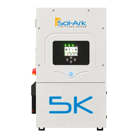
Solark
Solark 5K User manual
