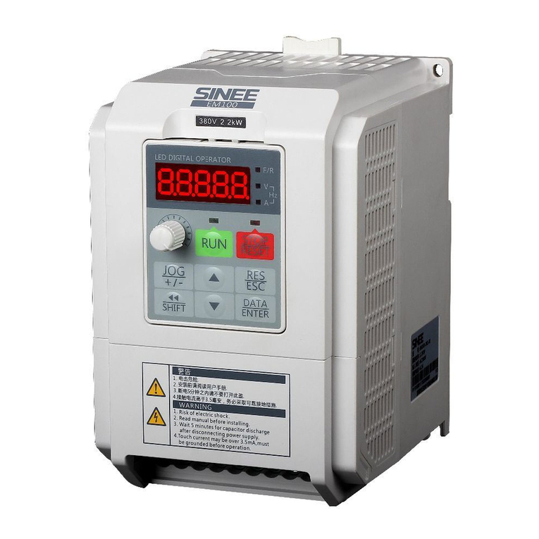
Sinee EM303A-1R1-1CB User manual

User Manual
EM303A General Purpose Inverter
1
Preface
Thank you for purchasing EM303A series inverter.
Document No.: 31010005
Issue Date: 06/06/2013
EM303A is a general purpose inverter (Speed Sensorless Vector Control). It helps an
induction motor to achieve not only the speed regulation standard of a DC motor, but also
the control ability of a torque motor, and the motion control system is optimized with
quick response, precise control and system stability.
The updates of EM303A:
1.Support Modbus RTU standard communication protocol.
2.Support RS485 master-slave communication control mode, numeric synchronized
control achieved.
3.Numeric input terminals support F/R logic control, delay input control, and etc.
4.Numeric output terminals support PWL/pulse output, F/R logic output and delay output,
and etc.
5.Analog input signals VS/IS/VF/IF can be programmed as numeric inputs, numeric
terminals expansion control achieved.
6.With filtering, analog input signals VP/VS/IS/VF/IF can actively avoid analog signals
interference and drift.
7.User can easily define the display of function code menus.
8.Run, stop and parameters setting status can program the displayed parameters
independently.
It is the duty of any user to perform the appropriate, correct installation or configuration
of the optional parameters of the devices. Neither SINEE nor its distributors shall be
responsible or liable for misuse of the information contained herein or mismatching the
inverter with the motor.
In the interests of commitment to a policy of continuous development and improvement,
SINEE reserves the right to update the specification of the product or its performance, or
the content herein without notice.

User Manual
EM303A General Purpose Inverter
2
Safety Information
The addition of this symbol to a Danger or Warning safety label indicates
that an electrical hazard exists, which will result in personal injury if the
instructions are not followed.
Thisisthesafetyalert symbol. It is used to alert you to potential personal
injury. Obey all safety messages that follow this symbol to avoid possible
injury or death.
Safety Precautions
Read and understand these instructions before performing any procedure with this
inverter.
● Verifying Product upon Delivery
Caution
1. Never install an inverter that is damaged or missing components.
Failure to comply can result in injury.
zInstallation
Caution
1. Always hold the case when carrying the inverter.
If the inverter is only held by the front cover, the main body of the inverter may fall, possibly
resulting in injury.
2. Installlation base shall be a metal plate or other non-flammable materials.
Installing the inverter on inflammable material may cause fire.
3. Install a cooling fan when installing more than one inverter in the same
cabinet, the temperature of the air entering the inverter shall be lower than
40℃.
Overheating may result in fire or other accidents.

User Manual
EM303A General Purpose Inverter
3
zWiring
Danger
1.Always turn off the input power supply before wiring.
Otherwise, an electric shock or fire may occur.
2.Wiring must be performed by authorized and qualified personnel.
Otherwise, an electric shock or fire may occur.
3.Be sure the ground terminals earthed.
Otherwise, an electric shock or fire may occur.
4.Always verify the function of emergency stop terminal in work after
connecting.
Otherwise, it may result in injury. (User takes the responsibilities of wiring).
5.Never touch the input or output terminals directly with bare hands, or
connect the terminals of inverter to the housing, or connect the input
terminals to output terminals.
Otherwise, an electric shock or short circuit may occur.
Caution
1.Always confirm if the voltage of AC input power supply satisfies the rated
voltage of inverter.
Otherwise, it may result in injury and fire.
2.Never perform voltage withstanding test.
Otherwise, semi-conductors and other devices can be damaged.
3.Connect braking resistor or braking unit according to required wiring.
Otherwise, a fire may occur.
4.Tighten terminals with screw drivers of specified torque.
Otherwise, a fire may occur.
5.Never connect input power supply cable to output terminals U, V, and W.
The inverter will be damaged if voltage is applied to the output terminals.
6.Never connect phase-shifting capacitor and LC/RC noise filter to output
circuits.
Otherwise, the inverter will be damaged.
7.Never connect the solenoid switch and electromagnetic contactor to output
circuits.
When inverter is with load, surge current, which is produced by the operation of
solenoid switch or electromagnetic contactor, will trigger the overcurrent
protection circuit to act. Sometimes the inverter will be damaged.
8.Never take off the interior wires of inverter.
Otherwise, the inverter will be damaged.

User Manual
EM303A General Purpose Inverter
4
zTrial Operation
Danger
1. Only after the front cover is installed, power can be turned on. Never take
off the front cover when power is on.
An electric shock may occur.
2. Do not come close to the machine at power failure if fault reset function is
active. The inverter will restart automatically when power is on.
An injury may occur.
3. Install an emergency switch for a quick brake in case of abnormal
conditions.
An injury may occur.
Caution
1. Never touch braking resistor. It will be very hot and with high-voltage when
running.
Otherwise, an electric shock and a burn injury may occur.
2. Reconfirm the motor and machine are within the applicable ranges before
starting operation.
Otherwise, an injury may occur.
3. Do not check signals while the inverter is running.
Otherwise, the inverter will be damaged.
4. Be careful when editing inverter settings. The inverter is in factory default.
Otherwise, the inverter will be damaged.
zMaintenance and Inspection
Danger
1. Do not touch inverter’s wiring terminals where high voltage exists.
Otherwise, an electric shock may occur.
2. Always keep the front cover in place before power is supplied to the inverter.
Turn off power before taking the front cover off.
Otherwise, an electric shock may occur.
3. Maintenance and check must be performed only after the power supply of
main circuit is turned off, and the indicator of CHARGE is off.
An electric shock may occur due to the residual voltage on electrolytic capacitor
after power is off.
4. Maintenance and inspection must be performed only by authorized
professionals.
Otherwise, an electric shock may occur.
5. Do not change the wiring and disconnect terminal wiring when power is on.
Otherwise, an electric shock may occur and the inverter will be damaged.

User Manual
EM303A General Purpose Inverter
5
Caution
1. CMOS ICs are installed on keypad, control circuit board and drive circuit
board respectively. Handle those parts and CMOS ICs carefully.
The CMOS IC can be destroyed by ESD if touched directly with bare hands.
2.Do not check signals while the inverter is running.
Otherwise, the inverter will be damaged.
zOther
Danger
1. Never attempt to modify or alter the inverter.
Failure to comply can result in electric shock or injury.
2. User shall take full responsibilities for the damages caused by wrong wiring,
improper operation or modifying and altering, and etc.

User Manual
EM303A General Purpose Inverter
6
CONTENTS
SUPPLEMENT FOR EM303A-XXX-1C, EM303A-XXX-2C ........... 8
1. OVERVIEW ................................................ 9
1.1EM303A MODEL LIST AND TECHNICAL SPECIFICATIONS .......... 9
1.2BASIC FUNCTIONS OF EM303A ............................ 11
1.3EM303A OPERATION STATUS DEFINITION .................... 13
1.4EM303A OUTLOOK ..................................... 17
2INSTALLATION ......................................... 18
2.1 VERIFYING PRODUCT ....................................... 18
2.2 OVERALL AND INSTALLATION DIMENSIONS ...................... 19
2.3CONSIDERATIONS OF INSTALLATION SITE .................... 21
2.4DIRECTION AND SPACE OF INSTALLATION .................... 21
2.5DISASSEMBLY AND ASSEMBLY OF KEYPAD ................... 22
3WIRING ................................................ 24
3.1CONNECTIONS TO PERIPHERALS ........................... 24
3.2WIRING MAIN CIRCUIT TERMINALS ......................... 25
3.3WIRING CONTROL CIRCUIT TERMINALS ..................... 32
3.4EXTENDING KEYPAD WIRE ............................... 38
3.5WIRING CHECK ........................................ 38
4KEYPAD OPERATION ................................... 39
4.1 TYPE AND FUNCTION OF KEYPAD .............................. 39
4.2LED KEYPAD OPERATION MODE ........................... 40
5TRIAL OPERATION...................................... 41
5.1TRIAL OPERATION PROCEDURES ........................... 41
5.2TRIAL OPERATION PRECAUTIONS ........................... 43
6PARAMETER TABLES ................................... 45
6.1FORMAT OF PARAMETER TABLES ........................... 45
6.2PARAMETERS .......................................... 46
SECTION 1GENERAL PARAMETERS ............................... 46
SECTION 2ADVANCED PARAMETERS .............................. 61
7PARAMETER DESCRIPTION ............................. 77
7.1GROUP F0: GENERAL PARAMETERS ......................... 77

User Manual
EM303A General Purpose Inverter
7
7.2GROUP F1: MOTOR PARAMETERS .......................... 88
7.3GROUP F2: INPUT/OUTPUT TERMINAL PARAMETERS ............ 91
7.4GROUP F3: PRESET SPEED PARAMETERS ..................... 99
7.5GROUP F4: GENERAL PARAMETERS OF PID .................. 104
7.6GROUP F5: GENERAL PARAMETERS OF VECTOR CONTROL ...... 112
7.7GROUP C0: MONITORING PARAMETERS ..................... 117
8 AUTOTUNING MOTOR PARAMETERS ...................... 119
8.1 AUTOTUNING MOTOR PARAMETERS ........................... 119
8.2PRECAUTIONS BEFORE AUTOTUNING ....................... 119
8.3AUTOTUNING PROCEDURE ............................... 120
8.4AUTOMATIC TORQUE BOOST AND SLIP COMPENSATION ......... 121
9 TROUBLESHOOTING ..................................... 123
9.1 FAULTS ................................................. 123
9.2FAULT ANALYSIS ...................................... 125
10 MAINTENANCE AND INSPECTION ........................ 128
10.1 MAINTENANCE AND INSPECTION ............................ 128
10.2DAILY INSPECTION .................................... 128
10.3PERIODIC MAINTENANCE ................................ 128
10.4PERIODIC MAINTENANCE AND REPLACEMENT OF PARTS ........ 129
10.5OUTLINE OF WARRANTY ................................ 129
11ACCESSORIES ......................................... 130
11.1 KEYPAD EXTENSION WIRE ................................. 130
11.2REMOTE OPERATION CASE .............................. 130
11.3 BRAKING RESISTOR ...................................... 131
11.4 BRAKING UNIT .......................................... 132
11.5 CONNECTING CABLE ..................................... 132
12 COMMUNICATION PROTOCOL OF EM303A ................ 133
12.1 APPLICATION SCOPE ...................................... 133
12.2 PHYSICAL INTERFACE ..................................... 133
12.3 PROTOCOL FORMAT ...................................... 133
12.4 DESCRIPTION OF PROTOCOL FORMAT ......................... 136
APPENDIX 1 ............................................... 139

User Manual
EM303A General Purpose Inverter
8
PBWUVL2L1
Supplement for EM303A-XXX-1C,
EM303A-XXX-2C
Except input voltage, applicable motor and power wire size, EM303A-XXX-1C and
EM303A-XXX-2C are the same as EM303A-XXX-3C in terms of installation, wiring,
operation and function codes, and etc.
1. Model and Specifications of EM303A-XXX-1C and EM303A-XXX-2C Inverter
(Open Loop Vector Control)
zRated voltage: 1-phase AC220V, 3-phase AC220V
zApplicable motor: 3-phase AC induction motor. Power ratings: 0.4~4.0 kW.
Rated voltage: AC220V
zOutput voltage: 3-phase, from 0 to Usupply.
Model and rated output current of EM303A-XXX-1C are shown in Table 0-1.
Table 0-1 Model List of EM303A-XXX-1C
Rated Input
Voltage Model No. Motor
Power(kW)
Rated Output
Current
(A)
Overall
Dimensions
Wire Size
(m2)
1-Phase
AC220V
EM303A-1R1-1CB 1.1 6.2 The same as
EM303A-2R2G
/3R0P-3CB
2.5
EM303A-1R5-1CB 1.5 8.0 4
EM303A-2R2-1CB 2.2 10.0 4
EM303A-3R0-1CB 3.0 13 The same as
EM303A-7R5G
/9R0P-3CB
6
EM303A-4R0-1CB 4.0 17 6
See Table 0-2 for model number and rated output current of EM303A-XXX-2C.
Table 0-2 Model List of EM303A-XXX-2C
Rated Input
Voltage Model No. Motor Power
(kW)
Rated Output
Current
(A)
Overall
Dimensions
Wire Size
(m2)
3-Phase
AC220V
EM303A-0R4-2CB 0.4 3.0
The same as
EM303A-2R2G
/3R0P-3CB
1.5
EM303A-0R5-2CB 0.55 3.7 1.5
EM303A-0R7-2CB 0.75 4.8 1.5
EM303A-1R1-2CB 1.1 6.2 2.5
EM303A-1R5-2CB 1.5 8.0 4
EM303A-2R2-2CB 2.2 10.0 4
EM303A-3R0-2CB 3.0 13 The same as
EM303A-7R5G
/9R0P-3CB
6
EM303A-4R0-2CB 4.0 17 6
2. Terminal Block of EM303A-XXX-1C and EM303A-XXX-2C
Terminal block of EM303A-XXX-1A is shown as below.
Terminal block of EM303A-XXX-2C is the same as that of EM303A-XXX-1C.

User Manual
EM303A General Purpose Inverter
9
1. Overview
1.1 EM303A Model List and Technical Specifications
zRated voltage: 3-phase, AC380V/415V
zApplicable motor: 3-phase induction motor, power range: 0.75~400kW.
Rated voltage: AC380V/415V
zOutput voltage: 3-phase, from 0 to Usupply.
1.1.1 EM303A Model and Rated Output Current
Table 1-1 Model List of EM303A
Rated Voltage Model No. Motor Power(kW) Rated Output
Current(A)
3-phase,
AC380V±20
%/415V±20%
EM303A-0R7G/1R1P-3CB 0.75 2.8
EM303A-1R1G/1R5P-3CB 1.1 3.7
EM303A-1R5G/2R2P-3CB 1.5 4.8
EM303A-2R2G/3R0P-3CB 2.2 6.2
EM303A-3R0G/4R0P-3CB 3.0 8
EM303A-4R0G/5R5P-3CB 4.0 10
EM303A-5R5G/7R5P-3CB 5.5 13
EM303A-7R5G/9R0P-3CB 7.5 17
EM303A-9R0G/011P-3CB 9.0 20
EM303A-011G/015P-3CB 11 26
EM303A-015G/018P-3CB 15 34
EM303A-018G/022P-3C 18.5 41
EM303A-022G/030P-3C 22 48
EM303A-030G/037P-3C 30 60
EM303A-037G/045P-3C 37 75
EM303A-045G/055P-3C 45 90
EM303A-055G/075P-3C 55 115
EM303A-075G/090P-3C 75 150
EM303A-090G/110P-3C 90 180
EM303A-110G/132P-3C 110 220
EM303A-132G/160P-3C 132 265
EM303A-160G/185P-3C 160 310
EM303A-185G/200P-3C 185 360
EM303A-200G/220P-3C 200 380
EM303A-220G/250P-3C 220 420
EM303A-250G/280P-3C 250 470
EM303A-280G/315P-3C 280 530
EM303A-315G/355P-3C 315 600
EM303A-355G/400P-3C 355 660
EM303A-400G/450P-3C 400 740
Remarks:
1.EM303A is an integrated model with G (Fixed torque) and P (square torque) in one.
The data listed above is of Model G. When applied to square torque like blower, water
pump and etc., the power ratings of applicable motor can be one grade higher. See the
details of inverter’s nameplate.
2.See 2.1 for the model numbering scheme.

User Manual
EM303A General Purpose Inverter
10
1.1.2 EM303A Technical Specifications
Table 1-2 EM303A Technical specifications
Items S
p
ecifications
Input
Rated Voltage 3-phase AC380V~415V±20%, 50~60Hz±5%, voltage imbalance rate <3%
Output
Output Voltage 3-phase, from 0 to Usu
pp
l
y
.
Rated Output Current 100% rated current non-stop output
Max. Overload Current Model G: 150% rated current for 1 minutes, 180% rated current for 2 seconds
Model P: 120% rated current for 1 minutes, 150% rated current for 2 seconds
Basic Control Functions
Control Mode V/F, SVC
Input Mode Frequency (Speed) input, torque input
Running Mode Keypad, control terminals (2-wire sequence, 3-wire sequence), RS485
Frequency Control Range 0.00~600.00Hz
Input Frequency
Resolution Numeric input:0.01Hz, analog input: 0.1% of maximum frequency
Governor Deflection 1:50(V/F), 1:100(SVC)
Speed Control Accuracy ±0.5% rated synchronous speed
Acceleration/Deceleration
Time 0.01~600.00 seconds/minutes
V/F Features Rated output voltage: 20%~100% adjustable, frequency base :20Hz~600Hz adjustable
Torque Boost Automatic torque boost, fixed torque boost curve, customer defined V/F curve scaling
Start Torque 150%/1Hz(V/F),150%/0.5Hz(SVC)
Torque Control Accuracy ±15% rated torque (SVC1)
AV R AVR is active while output voltage remains unchanged if input voltage is varying.
Automatic Current Limit Automatically limit output current, avoid frequent overcurrent tripping
DC Brake Brake frequency:0.1~60Hz, brake time:0~30S, brake current:0~100% rated current
Signal Input Source Communication, analog voltage, analog current, preset speed, simple PLC and their
combinations
Special
Function
Control
Textile Wobbulation Realize textile wobbulation functions like wobbulation range, time and jump
Droop Control With increase of load, the speed droops, suitable for one machine driven by multi-motor
Function of Input and
Output
Reference Power 10V/20mA
Terminal Control Power 24V/150mA
Numeric Input Terminals 7 programmable numeric input terminals
Analog Input Terminals 4 analog inputs:2 voltage inputs (0~10V), and 2 current inputs(0~20mA)
Numeric Output Terminal
s
2 OC outputs and 1 relay output are programmable. Maximum output current of OC:
50mA. Relay contact capacity: 250VAC/3A or 30VDC/1A. When relay acts, EA-EC is
NO, and EB-EC is NC.
Analog output Terminals 2 programmable analog output terminals can output 0~10V or 0~20mA
Keypad
Display
LED Human interactions with displays and control actuators
Parameter Copy Upload and download parameter information of the inverter, copy parameters rapidly.
Protections Protections Short circuit, overcurrent, overload, overvoltage, undervoltage, phase loss, overheating,
external fault, and etc.
Applica-tion
Conditions
Installation Site Indoor, with altitude less than1,000 meters, free from dust,corrosive gas, and direct
sunlight
Ambient Temperature -10℃~+40℃. In the temperature range +40 °C…+50 °C, the rated output current is
decreased by 1% for every additional 1 °C. 20%~90%RH (no condensation)
Vibration <0.5g
Storage Temperature -25℃~+65℃
Installation Method Wall mounting, or floor mounting
Degree of Protection IP20
Cooling Method Forced air cooling

User Manual
EM303A General Purpose Inverter
11
1.2 Basic Functions of EM303A
1.2.1 Process PID Control
2 process PID control modes: Speed process PID control and torque process PID
control. When output of process PID control is taken as inverter’s speed input, it
is speed process PID control. When output of process PID control is taken as
inverter’s torque input, it is torque process PID control. Speed process PID
control is applicable to all drive modes, while torque process PID control is only
active in SVC1.
Speed process PID control is used for:
zPressure control: Regulate motor speed by taking pressure signal as a feedback
to keep pressure constant.
zFlow control: Regulate motor speed by taking flow signal as a feedback to keep
flow constant.
zTemperature control: Regular motor speed by taking temperature signal as a
feedback, to keep temperature constant.
Torque process PID control is used for:
zTension control: Regulate motor’s torque current by taking tension signal as a
feedback to keep tension constant.
1.2.2 Program Operation (Simple PLC)
Program operation is that inverter finishes specified control logic according to the
mode and time set in the program. Program operation is categorized as speed
program operation, torque program operation and process PID program operation
(including speed and torque process PID program operation). The program
operation mode can be further categorized as: Single-cycle (stop after
completion), run at the 7th preset speed after single-cycle, limited continuous
cycle (stop after completion), and unlimited continuous cycle.
1.2.3 Wobbulation Operation (Textile only)
Wobbulation is applied to textile and chemical fiber industry that needs for
traverse and winding.
1.2.4 Stepping Mode Operation
Provide 5 stepping input modes for speed, torque and process PID input control
modes.
1.2.5 Droop Control
When the machine is driven by multi-motor, setting function of droop control can
evenly assign the output power of each inverter.
1.2.6 Stop Control at Power-off
When driving load with big inertia, the inverter will automatically enter stop
control status in case of power failure, and convert the rotational kinetic energy
into electrical energy to stop the motor quickly. It prevents the system from free
revolving with big inertia for a long time.

User Manual
EM303A General Purpose Inverter
12
1.2.7 Low Noise Design
Due to the high frequency harmonic wave with the output of inverter, the motor
generates the electromagnetic noise inevitably. Usually, electromagnetic noise can
be lowered by increasing carrier frequency, which, however, in turn makes the
inverter overheat, and the rated output current is required to be decreased by 5%
for every additional 1 kHz in carrier frequency. EM303A achieves low noise
operation with low carrier frequency by carrier frequency regulation.
1.2.8 Current Limit
When inverter is running, if acceleration/deceleration time is too short or the load
becomes heavier, the output current of inverter may exceed the permitted limit. If
current limit is enabled, inverter will automatically decrease its output frequency
to keep the output current limit unchanged. When output current is less than the
current limit, it runs as per regular input command. This function is applied to
V/F control mode only. For other control modes, the current is automatically
regulated.
1.2.9 Energy Autosaving
When motor is idling or with light load, EM303A will properly regulate its output
voltage for energy saving purpose.
1.2.10 Constant Power Output
With the same load, output current will increase as the input voltage of inverter
decreases. Meanwhile, if constant power output is active, the inverter will
automatically calculate its real-time output power and work at maximum power
permitted.
1.2.11 Automatic Voltage Regulation (AVR)
When the input voltage fluctuates, the output voltage remains unchanged
basically, and V/F value keeps constant.
1.2.12 Dynamic Overvoltage Stall
Effectively avoid bus voltage accumulation by real-time detecting voltage of DC
bus and regulate overvoltage points dynamically.
1.2.13 Dynamic Brake
When motor decelerates or runs with potential energy load, the voltage of DC bus
will rise due to energy feedback, and such voltage is called as rebounding
overvoltage. In order to make motor brake quickly within given deceleration time
while the inverter will not perform overvoltage protection, and rebounding
braking resistor or braking unit can be used to consume this energy, such brake is
called as dynamic brake.
1.2.14 Fault Autoretry
During operation of inverter, faults such as undervoltage (instant power failure
but resume immediately), overvoltage, overcurrent, and overload may occur. If
faults autoretry is active, inverter will automatically try to restart after a setting

User Manual
EM303A General Purpose Inverter
13
interval. Meanwhile, if speed search is active, inverter will automatically detect
motor speed and direction to make it return the setting input frequency smoothly.
1.2.15 Multi-function Numeric Input Terminals
7 multi-function numeric input terminals X1 ~X7 of EM303A can be
programmed based on real needs.
1.2.16 Multi-function Analog Output Terminals
Multi-function analog output terminals M0~M1 of EM303A can be defined as
different information, or as signals of 0~10V or 0~20mA.
1.2.17 Multi-function Numeric Output Terminals
The output of multi-function numeric output terminals Y1 and Y2, and relays of
EM303A can be programmed based on real needs.
1.2.18 Autotuning Motor Parameter
When autotuning motor parameters is enabled, the inverter will autotune and save
the motor parameters. (Autotuning motor parameter is categorized as stationary
autotuning and rotational autotuning. Please make motor in idling status by
separating motor and load if taking rotational autotuning mode. )
1.2.19 Parameter Copy
All function parameters of EM303A can be copied through keypad.
1.2.20 Programmable Displayed Information
Monitoring codes C0-00 ~C0-31 of EM303A can be displayed by setting
program.
1.2.21 RS-485 Interface
Through RS-485 interface and computer monitoring software, multi-inverter
operation can be easily achieved with computer network.
1.2.22 User Password
User can set password to protect function codes from unauthorized editing.
1.2.23 Overmodulated Output
When the load is heavy, overmodulation can raise the output voltage of inverter
and lower motor current, and then lower motor temperature rising.
1.2.24 Oscillation Suppression
Mechanical load may have mechanical resonance point, and motor may have
electromagnetic resonance point. Oscillation suppression can eliminate resonance
and enable system to operate stably and to be free from failures.
1.3 EM303A Operation Status Definition
1.3.1 Operation Status of Inverter
zParameters setting status: After power is on, inverter finishes initialization
enters standby status without fault or start-up command, and does not output.
zNormal running status: After receiving active start command through
keypad, control terminal or RS485, the inverter drives motor in accordance

User Manual
EM303A General Purpose Inverter
14
with the requirements of setting input.
zJOG running status: Set by keypad, external terminal or RS485 to make
motor run per JOG input speed.
zJOG stop status: Refer to the process that the output frequency drops to zero
in JOG deceleration time after JOG running command is not active.
zAutotuning status: Set by keypad to autotune motor’s parameters in
stationary or rotational autotuning.
zStop status: Refer to the process that the output frequency drops to zero in
given deceleration time after running command is not active.
zFault status: Status of inverter at protections, all kinds of faults and failures.
1.3.2 Control Modes of Inverter
The control modes of inverter refer to that the inverter controls motor rotation as
per required speed and torque with open loop or close-loop control mode. The
control modes include:
zGeneral open loop space vector control——V/F control
Applicable to the applications of slow speed changes and low speed stability
accuracy demand, and meet needs of most of AC motor drives.
zSVC 0—— Open-loop vector control without PG feedback
Only estimate speed in real-time, but no feedback control. Output current is
under real-time close-loop control, output of motor reaches 150% of rated
torque at 0.5Hz, and inverter automatically traces load variables and limit
output current to make it not exceed the maximum value. Even if there is
sudden load change, quick acceleration or deceleration, inverter will not trip
overcurrent, short-circuit, and etc., and keeps high performance and reliability.
zSVC1—— Torque control(Close-loop vector control without PG feedback)
Not only estimate speed in real-time, but also conduct feedback control. Speed
and current are under real-time close-loop control. Not only speed control but
also torque control can be realized. A regular AC induction motor can be
converted to AC variable speed motor and AC torque motor by adopting this
control mode. It is a genuine speed sensorless vector control.
1.3.3 Setting Modes of Inverter
The setting mode of inverter refers to that what kind of physical quantity inverter
is taken as control object when driving motor.
zSpeed setting mode is to take motor speed as the control object
zTorque setting mode is to take motor torque as the control object.
Set through various and flexible methods such as numeric setting, analog voltage,
and analog current or other mathematical combinations. Jog speed setting mode
is prior to other setting modes, i.e. when pressing JOG button on keypad or
making control terminals FJOG and RJOG on, no matter what the present setting
mode is, the inverter will automatically switch to jog speed setting. See Figure
1-1 and Figure 1-2 for the details of all speed setting modes of EM303A.

User Manual
EM303A General Purpose Inverter
15
Figure 1-1 Speed Setting Modes

User Manual
EM303A General Purpose Inverter
16
Figure 1-2 Torque Input Modes

User Manual
EM303A General Purpose Inverter
17
1.3.4 Operation Control Mode of Inverter
The operation control mode of inverter refers to the action conditions when
inverter enters operation status, which includes 3 modes as controlled by keypad
operation, terminal operation, and RS485 communication. Terminal operation
mode is categorized as 2-wire sequence, and 3-wire sequence. The setting details
and control logic of these three modes are shown in the description of function
parameters F0-04 and F0-05 in 7.1.
1.4 EM303A Outlook
See Figure 1-3 for the outlook of EM303A (Instance: EM303A- 4.0kW).
Figure1-3 EM303A Outlook
The face terminal cover can be taken away by following the arrow shown in
Figure1-3. See Figure 1-4 for control circuit terminals and main circuit terminals.
a. Control Circuit Terminal Block
PBWUVSTR
b. Main Circuit Terminal Block
Figure 1-4 Control Circuit Terminals and Main Circuit Terminals

User Manual
EM303A General Purpose Inverter
18
2Installation
2.1 Verifying Product
Refer to Table 2-1, and check and verify the EM303A.
Table 2-1 Check List
Item Action
If the products are identical to the
purchase order.
Check the devices reference marked on
the label.
Any part damaged. Check the outlook if any damages.
Any screw loosened. Check with a screwdriver if necessary.
Contact the distributor or SINEE directly for quality issue.
zNameplate
zModel Numbering Scheme

User Manual
EM303A General Purpose Inverter
19
2.2 Overall and Installation Dimensions
Classified to 10 sizes for total 30 models of EM303A, installation dimensions as
shown in Figure 2-1 and Table 2-2.
The keypad can be installed on the metal panel separately with a hole size of
116.5±0.1(L)*71.5±0.1 (W)mm, and applicable panel thickness:1.2~2.0mm
71
74
118
26
34
116
8
58
77
16
-R
2-M3
(a)Keypad Dimensions for Installation
W
W1
4-
d
H1
H
D
D1
D2
-R
D1
H2
H1
H
W
W1
2-d
D
-R
D2
(b) (c)
Figure 2-1 Overall and Keypad Dimensions of EM303A for Installation

User Manual
EM303A General Purpose Inverter
20
Table 2-2 Overall and Installation Dimensions of EM303A
Model No. WW1 H H1 H2 D D1 D2 dFrame
EM303A-0R7G/1R1P-3CB
140 125 220 205 -- 152 120 161 6 (b)
EM303A-1R1G/1R5P-3CB
EM303A-1R5G/2R2P-3CB
EM303A-2R2G/3R0P-3CB
EM303A-3R0G/4R0P-3CB
EM303A-4R0G/5R5P-3CB
EM303A-5R5G/7R5P-3CB
165 148 250 235 -- 161 126 170 6 (b)
EM303A-7R5G/9R0P-3CB
EM303A-9R0G/011P-3CB
215 150 352 335 317 215 172 224 7 (c)
EM303A-011G/015P-3CB
EM303A-015G/018P-3CB
EM303A-018G/022P-3C
270 200 470 450 424 245 187 254 10 (c)
EM303A-022G/030P-3C
EM303A-030G/037P-3C
EM303A-037G/045P-3C
335 240 550 530 500 245 190 254 10 (c)
EM303A-045G/055P-3C
EM303A-055G/075P-3C
390 300 695 665 635 250 200 259 12 (c)
EM303A-075G/090P-3C
EM303A-090G/110P-3C
560 400 828 803 775 355 255 364 12 (c)
EM303A-110G/132P-3C
EM303A-132G/160P-3C
EM303A-160G/185P-3C
650 400 1060 1034 1000 400 325 409 13 (c)
EM303A-185G/200P-3C
EM303A-200G/220P-3C
EM303A-220G/250P-3C
825 660 1200 1170 1137 400 320 409 13 (c)
EM303A-250G/280P-3C
EM303A-280G/315P-3C
EM303A-315G/355P-3C
1068 870 1213 1183 1150 410 330 419 13 (c)
EM303A-355G/400P-3C
EM303A-400G/450P-3C
Remarks:
z5 models: EM303A-055~075, EM303A-090~132, EM303A-160~200,
EM303A-220~280, and EM303A-315~400 can be floor-mounted with a chassis
which is in the same width as the inverter. Heights of optional chassis: 120mm,
250mm, 300mm, 300mm and 350mm.
zEM303A-090 or above: power input terminals are on the top, and power output
terminals are at the bottom of the inverter.
This manual suits for next models
42
Table of contents
Other Sinee Inverter manuals
Popular Inverter manuals by other brands
Federal Signal Corporation
Federal Signal Corporation PVS220W-24 installation manual

Greatwatt Energy
Greatwatt Energy S-700 owner's manual
Guardian
Guardian 4389 Diagnostic repair manual
CyberPower
CyberPower CPSHB300ETR user manual
Hitachi
Hitachi SJ Series Safety function Guide
Toyotomi
Toyotomi UTN-17AP user manual

Briggs & Stratton
Briggs & Stratton 40213 Installation and start-up manual
TOOLINE
TOOLINE HY70i user manual
brennenstuhl
brennenstuhl SES P1307 Instructions & user's manual
Stanley
Stanley PC1000S instruction manual

Berges
Berges ACM-D2 Series operating manual

Siemens
Siemens SINAMICS G180 Installation and operating instructions
