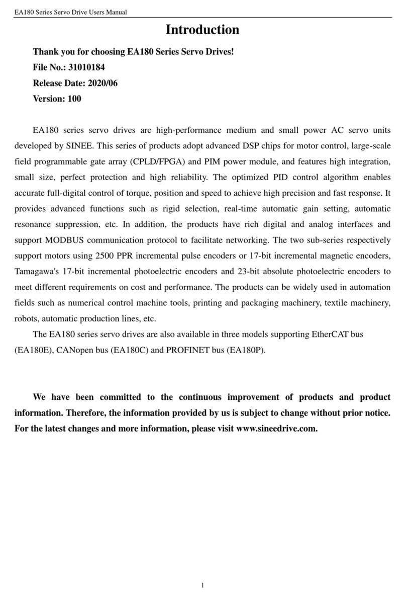
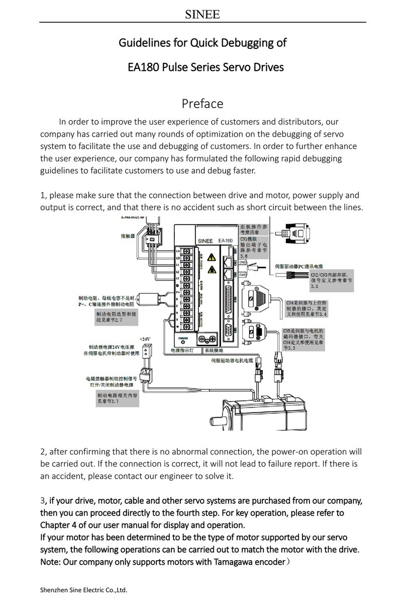
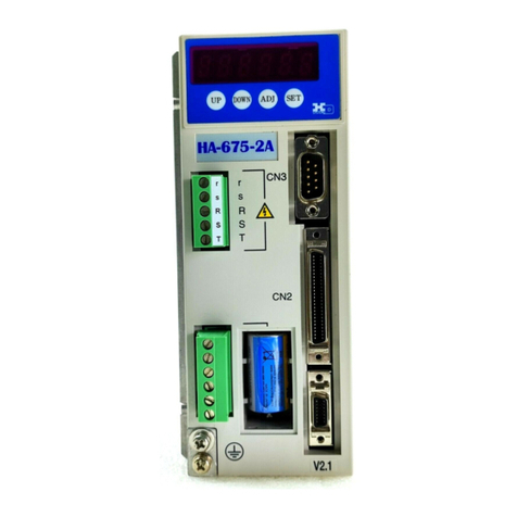
Sinee EA100-2R8-2A User manual

1
Preface
Thank you for purchasing EA100 series servo drive.
EA100 is a high performance general-purpose servo drive, which can be widely used in the numerically controlled machine
tools, printing and packaging machinery, textile machinery, robot automatic production line and other automation fields.
Since SINEE is committed to the development and improvement of products and products documents, this manual will be
updated without notice.

2
Safety Information
Danger: The label indicates that a failure to follow instructions can result in
serious injury or even death.
Caution: The label indicates that a failure to follow instructions can result in moderate or slight injury and device damage.
Please read this chapter carefully before system installation, debugging and maintenance and always follow the safety precautions below during
operation. SINEE will not undertake any damage or loss caused by a failure to follow the instructions.
Safety Precautions
Before Installation:
Danger
1. Do not install servo drive if its package is wetted or any its component is missing or
broken.
2. Do not install servo drive if the label information on its package is not identical to that on
servo drive.
Caution
1. Be careful when carrying or transporting servo drive so as to avoid damage!
2. Do not use servo drive if it is damaged or any component is missing so as to avoid
injury!
3. Do not touch the parts of control system with bare hands so as to avoid ESD!
During Installation:
Danger
1. Installation base shall be metal or other non-flammable material so as to prevent fire risk.
Caution
1. Ensure that no cable strips or screws are dropped servo drive so as to avoid damage to
servo drive.
2. Install servo drive at a place with less vibration and no direct sunlight.
3. Consider the installation space for cooling purpose when servo drive is installed in a
closed cabinet or space.
Wiring:
Danger
1、1.Wiring must be performed by authorized and qualified personnel so as to avoid unexpected
accidents.
2、2.A circuit breaker must be installed between servo drive and the mains so as to prevent fire
risk.
3、3.Ensure that power is off before wiring, and ground inverter in accordance with the
applicable wiring standard so as to avoid electric shock.
4、4.Grounding terminal must be grounded reliably so as to avoid electric shock and fire risk.
Caution
1、1. Never connect input power supply cable to output terminals U, V or W of servo drive. Pay
attention to terminal symbols and connect to the terminals correctly so as to prevent risks of
damaging servo drive.
2、2. Be sure that wiring meets EMC requirements and local safety standards. Cable should be in
recommended sizes so as to prevent accident risk.
3、3.Do not connect braking resistor to DC bus terminals + and –so as to prevent fire risk.
4、4.Tighten terminals with a screwdriver of specified torque so as to prevent fire risk.
5、5.Do not connect a phase-shifting capacitor or an LC/RC noise filter to output circuits.
6、6.Do not connect a solenoid switch or an electromagnetic contactor to output circuits.
Otherwise, it will trigger the action of the overcurrent protection circuit or even damage the
internal parts of servo drive.
7、7.Do not disconnect internal cable of servo drive, or else this can possibly damage the internal
parts of servo drive.

3
Before Power-on:
Danger
1、1.Verify that input voltage is identical to the rated voltage of servo drive, input terminals L1,
L2 and L3 and output terminals U, V or W are correctly connected, there are no short
circuit phenomena for the wiring of servo drive and its peripheral circuits, and all wires are
in good connection. Otherwise, this may result in servo drive damage.
2、2.Never perform voltage withstanding test on servo drive, because it has been done at the
factory. Otherwise, this may result in accident.
Caution
1、1.The front cover of inverter must be closed before inverter is powered on. Otherwise, it
may result in an electric shock.
2、2. The wiring of all peripherals must be conducted in accordance with the guidance of this
manual. Otherwise, it may result in an electric hazard.
After Power-on:
Danger
1. Do not touch servo drive or its peripheral circuits with wet hands to avoid the electric
shock.
2. If the indicator is off or the keypad does not display any information after power-on,
please cut off the power supply immediately. Never touch any terminal of L1, L2 or L3 of
servo drive or the connecting terminals with hands or a screw driver, or else an electric
shock accident may occur. Contact our customer service personnel immediately after
cutting off the power.
3. After being powered on, servo drive will automatically check the safety of the external
strong circuit automatically. Therefore, do not touch wiring terminal U, V or W of servo
drive or the wiring terminal of the motor with bare hands, otherwise it will result in electric
shock.
Caution
1、1.If you need to check parameter settings, be careful of personal safety when the motor is
running so as to avoid accidents.
2、2.Do not change default parameter setting without approval to avoid damage.
During Operation:
Danger
1、1. Never touch cooling fan, heat sink or discharge resistor with bare hands for checking
temperature, which may result in burning!
2、2. Only qualified technicians are allowed to detect signal during operation so as to prevent
personal injury or device damage.
Caution
1、1.Prevent any foreign items from being dropped into the device during operation, so as to
avoid damage to the device.
2、2. Do not control the start/stop of servo drive by ON/OFF of the contactor so as to avoid
damage to the device.
3.Do not contact the rotating shaft of the motor on running so as to prevent personal
injury..
Maintenance:
Danger
1、1.Maintain and inspect the device only after servo drive is powered off to avoid electric
shock.
2、2. Maintain and inspect servo drive only after its main circuit is powered off and CHARGE
indicator is off. Otherwise, the residual electric charge of capacitor may result in personal
injury.
3、3. Maintenance and inspection can be performed by well-trained technicians only, so as to
avoid personal injury or device damage.
4、4. Parameter setting is required if inverter has been replaced. Plug-in & plug-out should be
performed after power-off.
Attentions

4
Varistor or Power Factor Improvement Capacitor on Inverter Output
Servo drive outputs PWM wave. Do not use servo drive, if a power factor improvement capacitor or a lightning varistor is on output side, which
may easily result in transient overcurrent of servo drive, or even damage servo drive.
Surge Protection
A surge protection device is installed in servo drive to prevent it from induction lightning stroke on a certain degree. Additional protection
devices are required in front of servo drive in the places where thunder and lightning occur frequently.
Altitude and Derating
When servo drive is used in an area at an altitude of over 1,000m, the cooling effect will degrade, so it must be derated. For details, please
consult SINEE.
Attentions at Servo Drive Scrapping
Burning the electrolytic capacitors of the mains and PCB may result in explosion and burning plastic parts may generate toxic gas. Please handle
them as industrial wastes when servo drive is scrapped.

5
CONTENT
1 Product Information ..............................................................................................................6
1.1 Verifying Product ..........................................................................................................6
1.2 Model Numbering Scheme and Nameplate...................................................................6
1.3 Model Number List .......................................................................................................7
1.4 Servo Drive Control Mode............................................................................................ 7
2 Installation..............................................................................................................................8
2.1 Caution..........................................................................................................................8
2.2 Storage ambient conditions ...........................................................................................8
2.3 Installation ambient conditions......................................................................................8
2.4 Servo Drive Installation Direction and Space................................................................8
2.5 Servo Motor Installation Direction and Space...............................................................9
2.6 Circuit breakers and fuse recommendations................................................................10
2.7 Brake resistance selection............................................................................................ 10
2.8 EMI Filters ..................................................................................................................12
3 Display & Operation............................................................................................................ 13
3.1 Display and key operation Exterior............................................................................. 13
3.2 Display and operation mode........................................................................................13
3.3 Parameter setting Description...................................................................................... 13
3.4 Status Display.............................................................................................................. 14
3.5 Monitor display ........................................................................................................... 14
3.6 Fault and alarm display ...............................................................................................14
4 Wiring ...................................................................................................................................15
4.1 Peripheral connection..................................................................................................15
4.2 Main circuit wiring...................................................................................................... 15
4.3 CN5 encoder signal terminal.......................................................................................18
4.4 CN4 Control signal terminal ....................................................................................... 20
4.5 CN2, CN3 communication terminal wiring.................................................................31
4.6 CN1 analog output terminal ........................................................................................31
4.7 Holding brake.............................................................................................................. 32
4.8 Standard wiring diagram for control circuit................................................................. 34
4.9 Control circuit wiring precaution ................................................................................36
4.10 Servo drive main circuit block diagram.....................................................................36
5 Running and debugging.......................................................................................................38
5.1 Drive power on............................................................................................................38
5.2 Trial running................................................................................................................38
5.3 Servo enable method ................................................................................................... 38
5.4 Speed control mode.....................................................................................................39
5.5 Torque control mode debugging steps.........................................................................40
5.6 Gain parameter adjustment strategy ............................................................................40
6 Function Parameters............................................................................................................42
6.1 Function parameters define .........................................................................................42
6.2 Function parameter list................................................................................................42
7 Function parameter details..................................................................................................54
7.1 P0 group - Monitoring parameters............................................................................... 54
7.2 P1-xx Basic control parameters...................................................................................58
7.3 P2-xx Internal multi segment position (Pr) control parameter.....................................74
7.4 P3-xx Internal multi-speed control parameters............................................................76
7.5 P4-xxTorque control parameter...................................................................................76
7.6 P5-xx Gain tuning parameters.....................................................................................77
7.7 P6-xx Input and output(DI/DO)parameter................................................................... 82
7.8 P7-xx Communication parameters ..............................................................................87
7.9 P8-xx Auxiliary check even-parity function parameters..............................................88
7.9 Pb-xx the origin of regression function parameters.....................................................91
8 Communications protocol.................................................................................................... 96
8.1 Application Scope .......................................................................................................96
8.2 Physical interface ........................................................................................................ 96
8.3 Protocol format............................................................................................................96
8.4 Command interpretation..............................................................................................96
8.5 Protocol Format Description .......................................................................................97
8.6 Example....................................................................................................................... 98
9 Fault alarm and Treatment ................................................................................................. 99
9.1Fault Diagnosis and Treatment.....................................................................................99
9.2 Alarm Diagnose and Treatment Measures.................................................................102
10 Specification......................................................................................................................104
10.1 Technical specification............................................................................................ 104
10.2 Dimensions.............................................................................................................. 105
10.3 Motor specification..................................................................................................106
10.4 SER series servo motor dimension.......................................................................... 108
10.5 SER series servo motor overload characteristics..................................................... 110

6
1 Product Information
1.1 Verifying Product
Check and verify the product:
Item
Method
Check if they are identical to the
purchase order.
Check the nameplate at the side of inverter.
Any damage.
Check the overall appearance to see if they are
damaged in transportation.
Any loosened screws or other
fastening parts.
Check with a screw driver if necessary.
If you find any quality problem, please contact SINEE Direct Sale Department or the distributor.
1.2 Model Numbering Scheme and Nameplate
1.2.1 Nameplate
EA100 series servo drive
产品型号
适配电机功率
电源规格
输出规格
产品条码
产品序列号
额定输出电流
SER series servo motor
NOTE:The actual product nameplate may be different from as shown in the figure.
1.2.2 Model Numbering Scheme
Servo drive:
Servo motor:

7
1.3 Model Number List
Servo Drives
Matched Servo Motors
Model of servo
drives
Input voltage
Rated
output
current
Size
Model of servo motors
Motor
power
EA100-2R8-2A
1/3 phase AC
220V
2.8A
SIZE A
SER06-0R4-30-2AAY
400W
EA100-5R5-2A
5.5A
SER08-0R7-30-2AAY
750W
EA100-7R6-2A
7.6A
SIZE B
SER13-1R0-20-2ABY
1000W
EA100-010-2A
3 phase AC
220V
10.0A
SER13-1R5-20-2ABY
1500W
EA100-5R4-3A
3 phase AC
380V
5.4A
SER13-1R5-20-3ABY
1500W
EA100-8R4-3A
8.4A
SER13-2R0-20-3ABY
2000W
EA100-012-3A
12.0A
SER13-3R0-20-3ABY
3000W
EA100-018-3B
18.0A
SIZE C
SER18-4R5-15-3BBZ
4500W
EA100-021-3B
21.0A
SER18-5R6-15-3BBZ
5600W
EA100-030-3B
30.0A
SER18-7R5-15-3BBZ
7500W
1.4 Servo Drive Control Mode
The drive can provide multiple control modes for users, please refers to as follows:
Type
Control mode and
function parameter
Display
Specification
Single
mode
Position mode
P1-00=1
P
Drive accepts position command to control motor
Running at target position.
Position command input by terminal, signal is pulse.
Speed mode
P1-00=0
S
Drive accepts speed command to control motor running to
targer speed.
Speed command can be provided by internal register (3
groups) or analog voltage input terminal, and confirm which
use at present based on DI.
Torque mode
P1-00=2
T
Drive accepts torque command to control motor
running to target torque.
Torque command can be provided by internal register (3
groups) or analog voltage input terminal, and confirm which
use at present based on DI.
Mixed
mode
Speed and Position
switch mode
P1-00=3
S-P
S and P can switch by DI terminal.
Torque and Position
Switch mode P1-00=5
T-P
T and P can switch by DI terminal.
Speed and Torque
switch mode
P1-00=4
S-T
S and T can switch by DI terminal.

8
2 Installation
2.1 Caution
Please pay special attention to the following:
The cable between servo drive and servo motor should stay relaxed, not tense.
If the cable between servo drive and servo motor is more than 20 meters, please
Strengthen UVW connection and encoder connection.
When the servo driver is fixed, the installation direction must be in accordance with the regulations, and each fixed screw must be locked.
For the determination of concentric with the servo motor shaft and equipment shaft, to
prevent the radial stress when motor running.
Four fixed screws of the servo motor must be locked according to the prescribed torque.
In order to make the cooling effect better, when install AC servo drives, the upper and lower, left and right and adjacent items and baffle
(wall) must keep enough space, otherwise it will cause fault.
When the servo driver is installed, it can not be dumped. The air suction and exhaust holes are not blocked, otherwise, the fault can be
caused.
2.2 Storage ambient conditions
Please put the product in its packing box before installation. If the drive is not used, in order to enable the product to meet the company's
scope of warranty and future maintenance, be sure to pay attention to the following conditions:
2.3 Installation ambient conditions
2.3.1 EA100 servo drive using ambient conditions:
Item
Description
Dust and gas
No dust, free of corrosive gas or liquid.
Ambient humidity
Relative humidity 20%~90%(no condensation)
Ambient temperature
0℃~+45℃
Vibration
Below 4.9m/s²
Impact
Below 49m/s²
Elevation
Below 1000m,please derating above 1000m
2.3.2 SER series servo motor using ambient conditions:
Item
Description
Ambient humidity
Relative humidity20%~80% (no condensation)
Ambient temperature
0℃~+40℃
Vibration
Below 4.9m/s²
Impact
Below 49m/s²
Elevation
Below 1000m,please derating above 1000m
Do not use motor in closed ambient. Closed ambient will lead to high temperature of motor, shorten the service life.
2.3.3 Other caution
In addition to the above ambient conditions, regardless of the drive or motor, when selecting the installation site, please observe the
following precautions,otherwise, may make the product can not meet the company's warranty coverage and future maintenance:
No high temperature.
No water drops, steam, dust and oil dust.
No corrosive or flammable gas or liquid.
No floating fiber or metal particles.
Installation base shall be solid and free from vibration.
No electromagnetic interference and away from interference source.
2.4 Servo Drive Installation Direction and Space
Servo drive and servo motor appearance size and weight specifications, please refer to the chapter 10.
2.4.1 Method
Please ensure the installation direction and walls are vertical. To use natural convection or fan for cooling of the servo drive. Through the
mounting hole, the servo driver is firmly fixed on the mounting surface.
When installing, please turn the servo drive front (the operator's actual mounting face) to the operator, and make it perpendicular to the wall.
2.4.2 Cooling
Item
Description
Storage temperature
-20℃~+65℃(high temperature: 80℃72hours)
Storage humidity
Relative humidity of 0% to 95% with no condensation
Vibration
Below 49m/s²
Impact
Below 490m/s²

9
In order to ensure the air convection, please refer to Figure 2-1, around the servo drive with enough space.
In order not to make the ambient temperature of the servo drive partial excessive phenomenon, so that to maintain a uniform temperature of
electric cabinet, please install cooling fan above servo drive in electric cabinet.
2.4.3 Ground
Make sure the ground terminal is grounded, otherwise, there may be a risk of electric shock or interference arising from false action.
Figure 2-1 Servo Drive Installation Direction and Space
2.5 Servo Motor Installation Direction and Space
2.5.1 Motor installation
SER series servo motor must be installed in a dry and solid platform, please keep good ventilation and heat radiation effect, and keep a
good grounding.
2.5.2 Installation diagram
Item
Description
Anti-rust
solution
Wipe clean servo motor shaft extension ends of the "anti rust agent" before
installation, and then do the relevant anti rust treatment
Encoder note
Installation to prohibit the impact of the shaft extension end, otherwise it
will cause internal encoder fragmentation.
Pulley
installation
When installing the pulleys in the servo motor shaft with keyway ,please
use screw on the shaft end. In order to install pulley, at first, the double
headed nail is inserted into the screw hole of the shaft, washer is used on
the surface of the coupling end and a nut gradually locked into the
pulley.
About the servo motor shaft with keyway, use the screw holes of shaft
end to install. About the shaft of no keyway, adopt the wear coupling or
similar method.
When removing the pulley, adopt pulley removal device to prevent shaft
subjected to impact.
In order to ensure safety, a protective cover or similar device shall be
installed in the rotating area.

10
Item
Description
Centering
In connection with the machine, please use the coupling, as well as the
axis of the servo motor and mechanical axis to keep in a straight line, the
circumference radial pulsation of the shaft coupling should not be
greater than 0.03mm. If the centering is not sufficient, it will produce
vibration, it can damage the bearings and encoders etc.
Installation
direction
The servo motor can be installed in horizontal direction or vertical
direction, do not install slant, otherwise it may cause motor bearing
wear.
Oil solution
When using at the place of water droplets drop , please confirm the servo
motor on the basis of the protection level (except the shaft through part).
When using for the site of oil droplets will drop to the shaft through part,
please specify the use of oil seal with the servo motor.
The servo motor operating conditions with oil seal:
Please ensure the oil level is lower than the oil seal lip when
using.
Please use when oil seal can keep oil splash in a good condition.
In the servo motor vertical installation, please pay attention not to use oil
seal.
Shaft through part: Refers to the gap of motor shaft from the end surface of the
protruding part
Stress condition
of cable
Don't make cable excessive bending or tension is applied to it, especially the
core wire of the encoder signal line is 0.12 mm or0.22 mm, very fine, so in
wiring and using, please don't make the stretching tight.
Connector parts
solution
For connector parts, please note the following:
The connector, please confirm there is no garbage or metal debris and
other foreign bodies in connector.
The connector connects to the servo motor please first from one side of
the servo motor circuit cable and cable main grounding wire must
reliable connection. If first connected one side of the encoder cable, the
encoder may be fault caused by the potential difference between the PE.
The connection, please confirm the correct pin arrangement.
The connector is made of resin. Do not apply impact to prevent damage
to the connector.
When cable maintain connection to handle, please hold the servo motor
main body. If only seize the cable handling, may be damaged or broken
cable or connector.
If you need to bend the cable, you should pay full attention to the
wiring , do not make the connector part of the pressure or tension, or
may cause the connector damage or poor contact.
2.6 Circuit breakers and fuse recommendations
If there is a drive to install the leakage circuit breaker to be used as the leakage fault protection, to prevent leakage circuit breakers
malfunction, please select the model about the sense of current in the 200mA above and the action time of 0.1 seconds above.
Fuse, please use the fast fuse model, its rated current should be based on the drive capacity of about 1.5 times.
Strongly recommended: The fuse and circuit breakers recognized by UL/CSA .
2.7 Brake resistance selection
When the motor's output torque and speed in the direction of the opposite, the energy will be transmitted back to the drive from the load.
This energy will be poured into the bus bar so that the voltage value of the bus inside the drive is increased, and the magnitude of the recharge
energy depends on the inertia of the motor and the load. If the system inertia small, may through drive internal capacitors to absorb recharge
energy, but if the system inertia is large, more than the energy that capacity absorb, voltage value may rise too high, causing the drive stop or
even damage, so when the voltage rises to a certain value, recharge energy must by a braking resistor to consume.
The following table 2-1 lists commonly used SER series servo motor rotor inertia and EA100 drive internal capacitive absorption ability, and
retrogradation energy calculation formula.

11
Table 2-1 SER series servo motor rotor inertia and retrogradation capacity absorbed
Model
Motor
rotor inertia
42
( 10 )J kg m
Retrogradation
from rated speed
to motionless
without load
Eo (J)
Capacity
maximum
retrogradatio
n
Ec (j)
EA100-2R8-2□
SER06-0R4-30-2□AY
0.3
1.48
16
EA100-5R5-2□
SER08-0R7-30-2□AY
1.01
4.99
24
EA100-7R6-2□
SER13-1R0-10-2□BY
17.14
9.42
41
EA100-7R6-2□
SER13-1R0-20-2□BY
8.71
19.1
41
EA100-010-2□
SER13-1R5-20-2□BY
12.08
26.5
41
EA100-5R4-3□
SER13-1R5-20-3□BY
12.08
26.5
34
EA100-8R4-3□
SER13-2R0-20-3□BY
17.14
37.67
49.6
EA100-012-3□
SER13-3R0-20-3□BY
25.58
56.22
49.6
EA100-018-3B
SER13-4R5-15-3BBZ
35.37
43.73
61.2
EA100-021-3B
SER13-5R6-15-3BBZ
45.51
56.26
91.8
EA100-026-3B
SER13-7R5-15-3BBZ
79.89
98.76
91.8
retrogradation energy calculation formula:
v:rpm,motor maximum speed
The motor rotor inertia of servo motor with brake is same with servo motor without
brake’s.
2.7.1 Built-in brake resistance
There is brake resistance in EA100 series drive, suitable for the general situation of the load inertia. About EA100 series built-in brake
resistance specifications, please refer to Table 2-2.
Table2-2 EA100 drive built-in brake resistance allowable minimum external brake resistance
Model
Brake resistance(built in)
Retrogradation
treated by built in
brake resistance
Allowable
minimum
external brake
resistance
Resistor(P8-18)
Capacity(P8-19)
EA100-2R8-2□
50Ω
100W
50W
50Ω
EA100-5R5-2□
50Ω
100W
50W
50Ω
EA100-7R6-2□
50Ω
100W
50W
40Ω
EA100-010-2□
50Ω
100W
50W
40Ω
EA100-5R4-3□
50Ω
100W
50W
50Ω
EA100-8R4-3□
50Ω
100W
50W
50Ω
EA100-012-3□
50Ω
100W
50W
45Ω
EA100-018-3B
40Ω
200W
90W
30Ω
EA100-021-3B
40Ω
200W
90W
30Ω
EA100-026-3B
40Ω
200W
90W
25Ω
2.7.2 External brake resistance capacity calculation
When the retrogradation capacity exceeded retrogradation capacity internal brake
resistance can dealt with, should use external braking resistance.
According to the calculation formula of retrogradation , assuming the load inertia is N times the inertia of the rotor of the motor, motor
from the rated speed to 0, retrogradation is (N+1) *Eo, the action cycle is T, then
Power of braking resistance
2.7.3 Note when using external braking resistance
When using external braking resistor, resistor connected to the P+ and C terminal, at the same time must remove the short circuit piece
installing between P+ and D, makes P and D two terminals in the open state.
The external braking resistance cannot be less than reported in table 2-2, otherwise it might damage the drive.
Please make the external resistor braking resistor value and the capacity set to the function parameters of drive correctly, otherwise it will
affect the execution of the function.
P8-18 (brake resistance), P8-19 (brake resistance capacity).
In the natural environment, when the braking resistor can handle retrogradation capacity (average) below the rated capacity, resistance
temperature will rise to 120℃above(in the continuous braking condition). For security, please use the forced cooling system, to reduce
the temperature of the brake resistor; or recommend the use of braking resistor with thermo switch. The load characteristics on braking
resistance, please refer to the manufacturer.
Note:
1) Please make the external braking resistor same with the internal braking resistor, otherwise,
may lead to drive damaged.
)(182/
2
0JJ v
E
T
NEE C))1((20

12
2) When using external braking resistance, if don‘t remove the short circuit piece which is
between P and D, it may lea to drive damaged.
2.8 EMI Filters
All of the electronic equipment (including servo drives) in normal operation, will produce some high frequency or low frequency noise, and
through the conduction or radiation interference peripheral equipment. If you can match the appropriate EMI filter and the correct installation
method, the interference will be reduced to a minimum.
When the servo driver and EMI filter are installed, we can follow the installation and wiring of the contents of the manual, we can be sure that it
can meet the following specifications:
1. EN61000-6-4(2001)
2. EN61800-3 (2004)PDS of category C2
3. EN55011+A2(2007)Class A Group 1
2.8.1 EMI Filter installation caution
In order to ensure that the EMI filter can achieve maximum effect of inhibit the servo drive interference, in addition to the servo drive
according to the contents of the manual installation and wiring, still need to pay attention to the followings:
1) Servo drive and EMI filter must be installed on the same piece of well grounded metal plane.
2) Servo drive and EMI filter, please try to install the servo drive above the EMI filter .
3) All wiring will be as short as possible.
4) Metal shell of servo drive and EMI filter must be reliably connected with the metal ,surface, and the contact area between the two should be
as large as possible.
2.8.2 Selection of motor cable and installation notes
The selection and installation of the motor line is correct or not, it’s related to the EMI filter can play the greatest effect of servo drive
interference suppression.
Please note the followings:
1) The cable with isolation copper mesh (Double isolation layer is preferred).
2) The isolated copper mesh on both ends of motor line to ground in the shortest distance and the maximum contact area.
3) Motor line isolation copper mesh connects metal plane correctly, isolated copper mesh on both sides of motor line should be fixed with
U-shaped metal piping supports and metal plane.

13
3 Display & Operation
3.1 Display and key operation Exterior
Mode key UP key DOWN key Left key Set key
Digital display
EA100-8R4-3A
01020052111410280001
MOD SET
88888 Drive model
and serial
number
3.2 Display and operation mode
There are 5 display and operation mode for EA100 servo drive
Mode
Function
Monitor mode
Monitoring the value of parameter code
Parameter group
selection mode
Choose parameter group to be monitored or set
Parameter code
selection mode
Choose parameter code to be monitored or set
Setting Mode
Setting the value of the selected parameter code
Fault and alarm mode
Display fault and alarm information
3.3 Parameter setting Description
1) When the drive is powered on, the digital tube display the default monitor code for one second, then work in monitor mode.
2) In monitor mode, pressing UP or DOWN key to change the monitored parameter code, then press the SET key to monitor selected
parameter code. If there is no key operation, it will monitor selected parameter code automatically after one minute.
3) In monitor mode, if the monitored parameter is 32 bit or displaying a more than 5 digits binary number, press the left key to switch the
display for high bit and low bit. When displaying high bit, the digital tube decimal point of the highest bit is lit.
4) In monitor mode, press MOD to enter the parameter set selection mode, then press UP / DOWN key to switch the parameter set, press the
MOD key to exit the parameter set selection mode back to monitor mode.
5) In parameter group selection mode, pressing left key, the flashing character shift left. It is easy to choose parameter group number. Press
SET key to enter parameter code selection mode, press MOD key to exit parameter code selection mode and back to parameter group
selection mode.
6) In parameter code selection mode, pressing UP or DOWN key can change the value of last two code to change parameter code, then press
the SET key immediately to enter the parameter setting mode and display the value of the parameter code.
7) In the parameter setting mode, use UP / DOWN key to set parameter. When pressing left key the blinking character will shift left, it is
easily and quickly to modify the value of the parameter high bit.
8) After setting the value, press SET key to store or execute a command.
9) After setting the value, the digital tube will display the status information of the parameter, for example, displaying -End-. Then
automatically back to parameter code selection mode.
10) In parameter setting mode, press MODE key or no key operation in one minute will cancel the modification of parameter value, and back
to parameter code selection mode.
11) When servo alarm, pressing MODE key for one second, it will show the current alarm code; pressing any key again to exit the alarm code
displayed.
Alarm display Monitoring
parameter Basic control
parameter Internal multi-
location parameters Auxiliary function
parameter
...
Or
MOD MOD
SET Display parameter settings
SET Storage Parameters
MOD
Double-click
or Shift Left
Fault
Fault
Fault
Fault
Fault
MOD MOD
MOD
Double-click
MOD
Double-click
AL00
1
P0-00
P0-01
P0-02
P1-00
P1-01
P1-02
P2-00
P2-01
P2-02
P8-00
P8-01
P8-02
10000
10001
-EnD-

14
Figure 3-1 Panel Operation flowchart
3.4 Status Display
There are following states:
Display symbol
Content note
-End-
The set value is stored correctly.
Po-0n
This parameter must be rebooting to be effective.
Sru0n
Parameter cannot be set when servo starting
Err-r
Read - only parameters, which cannot be modified
EESud
This parameter is reserved and cannot be modified.
3.5 Monitor display
Press the MOD key twice or no key operation more than one minute, servo drive will automatically enter monitor display group function code
P0---, in monitor mode, you can press UP or DOWN key to change the monitoring code.
Example
Describe
P0-00
Press SET key to display the motor speed
P0-01
Press SET key to display the motor load rate
P0-02
Press SET key to display current electric angle
P0-30
Press SET key to display received external pulse frequency
3.6 Fault and alarm display
Example
Describe
AL0nn
When there is a fault in the drive, it will be shown in the panel and
displaying fault code "Al0" and "NN". "NN" ranges from 01 to FFH.
Pressing operation key for other display, but the decimal point of the
lowest digital tube will be flashing, until it is cleared, there are no fault or
displaying AL--- when warning
ALEnn
When the drive alarms, it will be shown in the panel and displaying
warning code "AlE" and "NN". Pressing operation key for other display,
but the decimal point of the lowest digital tube will be flashing, until the
alarm is cleared.

15
4 Wiring
4.1 Peripheral connection
CN2
CN3
When braking resistance or bus
capacitance is insufficient, an
external braking resistor should
connect to P+ terminal and C
terminal
+24V
Electromagnetic contactor
brake control signal.
Open / Close brake power
supply
EMI filter
24V power supply for
brake (only for servo
motor with brake)
System ground
PC communication cable
of servo drive
Servo motor cable
Contactor
Servo motor
3-phae 220V AC / 380V AC
Breaker
CN1 analog
output terminal.
Please see
section 3.6 for
the circuit.
CN2 / CN3 internal
connected in parallel.
Please see section 3.5
for signal definition
Please see section 4
for panel operation
CN4 is connected to the
upper computer.
Please see section 3.4 for
definition and use of CN4
CN5 is connected to servo
motor encoder.
Please see section 3.3 for
definition and use of CN5
Please see section 2.8 for
selection and wiring of
braking resistor
Please see section 3.7
for braking circuit
Power indicator
SINEE EA100
L1C
L2C
L1
L2
L3
P+
D
C
U
V
W
CHARGE
CN1CN2CN3CN4CN5
电源 POWER 电机 MOTOR
制动 BRK
直流母线
Remark:
1) The servo drive is connected to the industry power supply directly, and there is no power isolation like transformer. To prevent electric
shock of servo system, please put a fuse or molded case circuit breaker in the input power supply.
2) Do not install electromagnetic contactor between the drive and the motor, which can damage the drive.
3) Please note the power supply capacity when connect to external control power supply or 24V power supply, especially when the power
supply is connected to several drives or brakes. If power supply capacity is not enough, the output current will also be not enough,
which can lead to the damage of drive or brake. Please note that the brake power supply is 24V DC, whose capacity should be
consistent brake power. Please refer to describe of servo motor for related brake power.
4) Check the servo motor output U, V, W terminal wiring phase. The motor will not run or run out of control and then alarm, or even
damaged by incorrect wiring.
5) When using external resistor, P+ and D terminal should be open, and the external brake resistor should be connected to P+, C terminal.
When using internal brake resistor, P+ and D terminal should be shorted and P+ and C terminal should be open.
6) In 1-phase 220V wiring, the main power supply terminal is L1, L2 terminal, and L3 should be empty.
7) CN2 and CN3 are same defined communication terminals, so that you can use any one of them.
4.2 Main circuit wiring
Main circuit (strong electric part) terminals and screw size are shown below.

16
L1C
L2C
L1
L2
L3
P+
D
C
U
V
W
SIZE
Main circuit terminal
Screw Size
Tightening
torque
SIZE A
M4
2.5N.m
SIZE B
M4
2.5N.m
SIZE C
M4
2.5N.m
SIZE
PE ground terminal
Screw Size
Tightening
torque
SIZE A
M4
2.5N.m
SIZE B
M4
2.5N.m
SIZE C
M4
2.5N.m
4.2.1 Main circuit (strong electric) terminal Introduction
Table 4-1 servo drive main circuit terminal
Terminals
markings
Terminal name
Terminal Function
L1C, L2C
Control power supply
input terminals
1-phase input which is consistent with the main circuit
power supply voltage level
L1, L2, L3
Main circuit AC
power input terminals
EA100-2R8-2□
EA100-5R5-2□
EA100-7R6-2□
L1, L2 1-phase 220V input
L1, L2, L3 3-phase 220V input
EA100-010-2□
L1, L2, L3 3-phase 220V input
EA100-5R4-3□
EA100-□□□-3□
EA100-026-3□
3-phase 380V input
P+,D,C
External braking
resistor connection
terminals
Default connection between D and P +.
When the braking is insufficient, please keep P +, D
circuit open, and connect an external braking resistor
between the P + and C.
P+,
DC bus terminal
DC bus terminal of servo drive. It can be shared when
multi-parallel.
U,V,W
Servo motor
terminals
Connection terminals of the servo motor and they are
connected to U, V, W of the motor
PE
Ground
One ground terminal for EA100-2R8-2A and
EA100-5R5-2A; Two ground terminals for other power
drives. It is connected to the ground terminal of power
supply and the ground terminal of motor.
4.2.2 Power Wiring
Servo drive power connection is divided into 1-phase and 2-phase. 1-phase only for the drives with output current 7.6Aand less than 7.6A
1-phase power supply wiring (rated output current ≤7.6A)
Figure 4-1 1-phase power supply wiring diagram
3-phase power supply wiring (all series are applicable)

17
Figure 4-2 3-phase power supply wiring diagram
Remark:
1: If you do not want to cut off the main circuit power supply when a failure occurs, RA relay is
not necessary.
2: L1C, L2C can be connected to P +, - terminals instead of external power supply.
Power on timing
Control circuit power
supply
Mains supply
Servo ready output
(S-RDY)
Servo enable
(S-ON )
Servo motor
excitation
Unpowered
Powered
Unpowered
Powered
Not ready Ready
Enable invalid
Not receive
instruction
Motor
Unpowered
Motor
powered
Not receive
instruction
Receive instruction
Position / speed /
Torque command
Delay1.5S
Delay as P1-54 set
Servo enable signal
(S-ON signal) Invalid Valid Invalid
Enable invalid
Motor
Unpowered
Enable valid
Figure 4-3 power-on timing chart
Please refer to figure 3-1 and 3-2 for power wiring and wire as followed sequence.
1) Control power circuit L1C, L2C must be powered on before the main circuit or at the same time as the main circuit power supply. If only
the power control circuit is powered on, the servo ready signal (S-RDY) will be invalid.
2) The main circuit power input terminals should be connected to the mains supply by electromagnetic contactor (3-phase: L1, L2, L3, 1
phase: L1, L2).
3) After the main circuit power supply is powered on and a 1.5-second delay, servo ready signal (SRDY) will be valid, then it can accept the
servo enable (S-ON) signal. When detecting the servo enable signal is valid, the motor will be activated, and running. When detecting the
servo enable is invalid or alarmed, output of drive will be off, and the motor is in a free state.
4) When the servo enable and the mains supply are powered on at the same time, the motor will be activated after 1.5 second.
5) Frequently turning on or off of the main circuit power supply may damage the soft start circuit and dynamic braking circuit. The frequency
of tuning on or off should be less than 5 times one hour, and 30 times one day. When the drive or motor is overheating, after the solving
the problem, the main circuit should be powered on again after 30 minutes cooling.
6) The input power cable cannot connect to the output terminals U, V, W, which can damage the servo drive.
7) The braking resistor is absolutely prohibited to be connected to the DC bus P +, terminals, which may lead a fire.
8) After the power is turned off, there may be residual voltage in the servo drive internal capacitance, confirm the CHARGE indicator on the
servo drive panel is off before other operation.
4.2.3 Connector specification of motor power cables
Table 4-2 motor servo motor power cable connection terminals
Connector shape and model
Terminal pinout
Motor
flange size
12
34
Shell model:C4140HM-2X2P
4PIN AMP Plug(without brake)
Pin
Define
1
U
2
V
3
W
4
PE
60
80
86

18
Connector shape and model
Terminal pinout
Motor
flange size
Plug model:C4140F-TP-H
1
23
4
Model:YD28K4TS
Aviation plug(without brake)
Pin
Define
1
PE
2
U
3
V
4
W
130
1
23
4
56
7
Model:YD28K7TS
Aviation plug(with brake)
Pin
Define
1
PE
2
24V(brake)
3
0V(brake)
4
not used
5
U
6
V
7
W
130
Note: Due to the product improvement, the aviation plug model may be changed.
4.2.4 Specifications of recommended cable for main circuit connection
Model
L1C,L2C
L1,L2,L3
P+,C
U,V,W
PE
EA100-2R8-2□
0.5mm2
1.0mm2
1.0mm2
1.0mm2
2.5mm2
above
EA100-5R5-2□
EA100-7R6-2□
2.0mm2
2.0mm2
2.0mm2
EA100-010-2□
EA100-5R4-3□
1.0mm2
1.0mm2
1.0mm2
EA100-8R4-3□
2.0mm2
2.0mm2
2.0mm2
EA100-012-3□
EA100-018-3B
4.0mm2
4.0mm2
4.0mm2
EA100-021-3B
EA100-026-3B
6.0mm2
6.0mm2
6.0mm2
4.3 CN5 encoder signal terminal
CN5 is encoder signal terminal (DB15 socket), its position is shown in Figure 3-4:
1
2
3
4
5
6
7
8
9
10
11
12
13
14
15
SINEE EA100
L1C
L2C
L1
L2
L3
P+
D
C
U
V
W
CHARGE
电源 POWER 直流母线 制动 BRK 电机 MOTOR
CN1CN2CN3CN4CN5
Figure 4-4 CN5 terminal positions
4.3.1 Encoder terminal definition drive-side

19
5
10
4
9
3
8
2
7
1
15
14
13
12
11
6
Encoder B+ signal
Encoder B- signal
Encoder A+ signal
Encoder A- signal
Shielded layer
connect to PE
Encoder Z- signal
Encoder U- signal
Encoder V- signal
Encoder W- signal
Encoder power
supply 5V
Encoder Z+ signal
Encoder U+ signal
Encoder V+ signal
Encoder W+ signal
GND 5
10
4
9
3
8
2
7
1
15
14
13
12
11
6
Shielded layer
connect to PE
Encoder power
supply 5V
SD+
SD-
GND
CN5 2500ppr incremental encoder terminal definition CN5 17-bit encoder terminal definition
It indicates that the
terminal Is Left,
and do not connect
Note: When connected to
the wire-saving encoder, U
+ / U-, V + / V-, W + / W-,
Need not to be connected.
Figure 4-5 CN5 terminal pinout
2KΩ
100Ω
100Ω
1
33
34
上位机装置
100Ω
100Ω
31
32
14
16
PULSE+
PULSE-
SIGN+
SIGN-
GND
PE
GND
GND
伺服驱动器
普通脉冲位置指令
最小脉冲宽度1us
最大输入频率为500kpps
PULHIP
PULHIS
1
6
11
5
10
15
Figure 4-6 CN 5 terminal welding pinout
4.3.2 Encoder terminal definition of servo motor side
There are two shapes encoder terminal in the servo motor side.
AMP plug,for motor with 60, 80 flange, the pin defined in Table 4-3a, 3b, 3c
Plugs in motor side
Shape
2500ppr incremental encoder
17 bit encoder
4 532
1
9 107
6
14 151312
11
8
Motor side
321
64
987
5
Motor side
Encoder cable connector
15
610
11
15
234
9 7
12
1314
8
123
6 4
7
89
5
Shell model:
C4140-HM-3*5P
Plug model:
C4140F-TP-L
Shell model:
C4140-HM-3*3P
Plug model:
C4140F-TP-L
Aviation plug: for motor with 110 flange and above, the pin defined in Table 4-3a, 3b, 3c
2500ppr incremental encoder
17 bit encoder
2
5
14
13
15
11
10
6
3
1
Terminal type:YD28K15TS
Note: Due to the product improvement, the aviation plug model may be changed.
Table 4-3a 17-bit incremental encoder cable connection
Function
Description
Drive side DB15
Servo motor side
AMP plug
Aviation plug
Signal name
Pin
Pin
Pin
Encoder power
supply
+5V
5
1
2
Encoder power
GND
10
2
3

20
Function
Description
Drive side DB15
Servo motor side
AMP plug
Aviation plug
Signal name
Pin
Pin
Pin
supply ground
Positive terminal
of serial signal
SD+
1
5
4
Negative terminal
of serial signal
SD-
3
6
7
Shield layer PE
PE
Shell
9
1
Table 4-3b 17-bit absolute encoder cable connection
Function
Description
Drive side DB15
Servo motor side
AMP plug
Aviation plug
Signal name
Pin
Pin
Pin
Encoder power
supply
+5V
5
1
2
Encoder power
supply ground
GND
10
2
3
Positive terminal
of serial signal
SD+
1
5
4
Negative terminal
of serial signal
SD-
3
6
7
Positive terminal
of external battery
VB+
7
14
Negative terminal
of external battery
VB-
8
15
Shield layer PE
PE
Shell
9
1
Table 4-3c 2500ppr non-wire-saving encoder cable connection
Function
Description
Drive side DB15
Servo motor side
AMP plug
Aviation plug
Signal name
Pin
Pin
Pin
Encoder signal Z +
Z+
1
7
6
Encoder signal U +
U+
2
6
10
Encoder signal V +
V+
3
10
11
Encoder signal W +
W+
4
11
12
Encoder supply 5V
+5V
5
2
2
Encoder signal Z-
Z-
6
5
9
Encoder signal U-
U-
7
8
13
Encoder signal V-
V-
8
12
14
Encoder signal W-
W-
9
15
15
Encoder power
supply ground
GND
10
3
3
Encoder signal B +
B+
11
4
5
Encoder signal B-
B-
12
14
8
Encoder signal A +
A+
13
9
4
Encoder signal A-
A-
14
13
7
Shielding layer PE
PE
Shell
1
1
Remark for servo wiring:
1) Make sure the drive and the motor shielded layer are grounded; otherwise it will cause the drive error.
2) Do not confuse GND and PE.
3) Be sure that the differential signal can match the two cables of a twisted pair. For example, A + and A- is a set of differential signal, you
should use a twisted pair.
4) Encoder cable routing must be separated from the power cable routing by at least 30cm or more.
4.4 CN4 Control signal terminal
Using the DB44 socket, CN4 signal terminal provides signals for communication with upper computer.
Signals include:
8 programmable digital inputs
4 programmable digital differential output
This manual suits for next models
19
Table of contents
Other Sinee Servo Drive manuals
Popular Servo Drive manuals by other brands
RHINO MOTION CONTROLS
RHINO MOTION CONTROLS RMCS-1110 Installation Manual and Datasheet
Omron
Omron R88D-KTA5L user manual
Kollmorgen Seidel
Kollmorgen Seidel 6SM56 Series Technical description
Siemens
Siemens SIMOTICS S-1FL6 Compact operating instructions
Minimotors
Minimotors DBS 55 Series Installation, use and maintenance manual
Omron
Omron OMNUC G Series user manual
