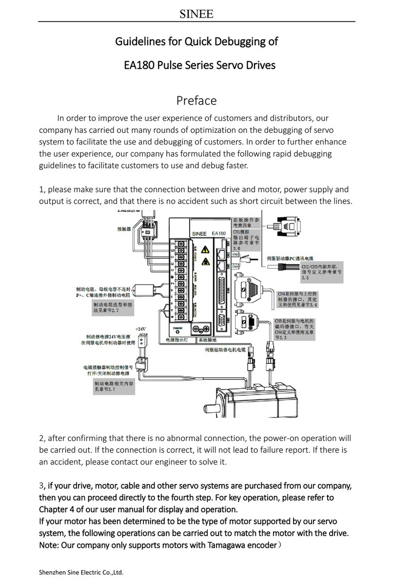
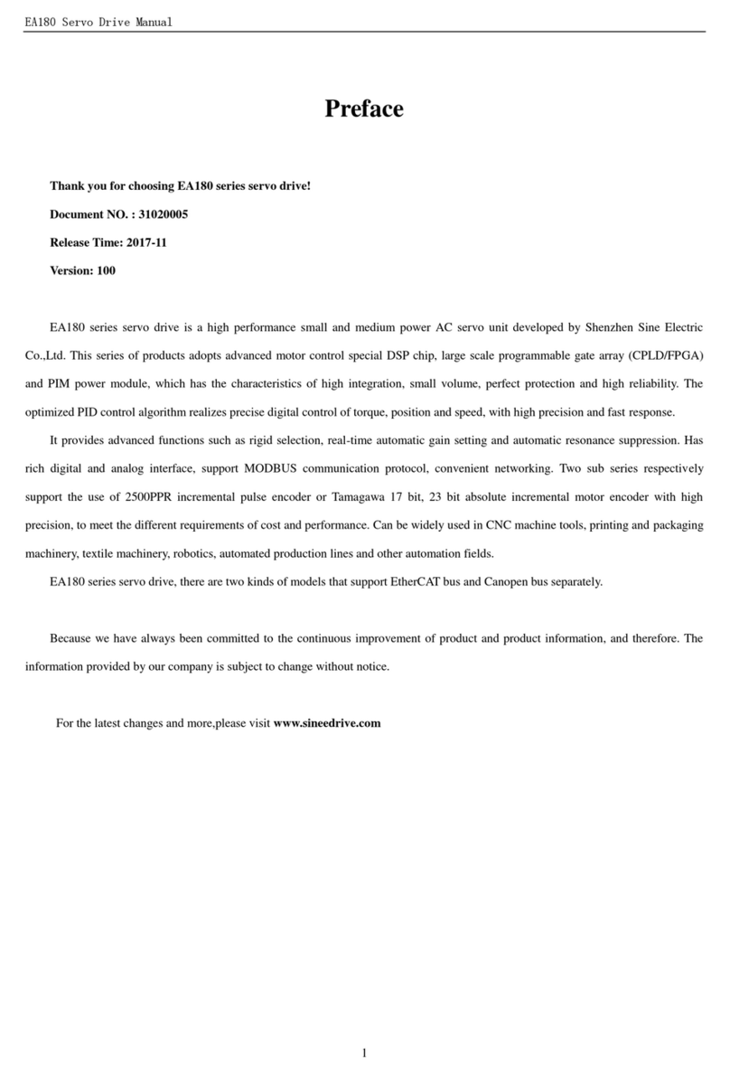
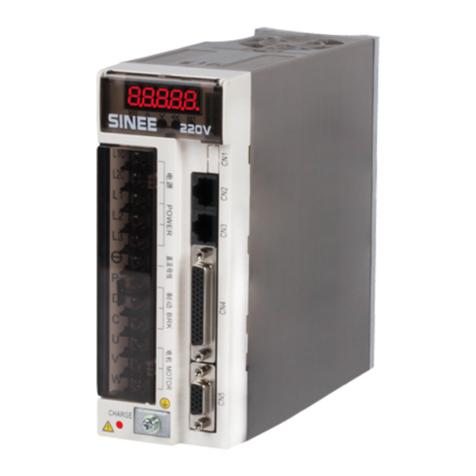
Sinee EA180 Series User manual

EA180 Series Servo Drive Users Manual
1
Introduction
Thank you for choosing EA180 Series Servo Drives!
File No.: 31010184
Release Date: 2020/06
Version: 100
EA180 series servo drives are high-performance medium and small power AC servo units
developed by SINEE. This series of products adopt advanced DSP chips for motor control, large-scale
field programmable gate array (CPLD/FPGA) and PIM power module, and features high integration,
small size, perfect protection and high reliability. The optimized PID control algorithm enables
accurate full-digital control of torque, position and speed to achieve high precision and fast response. It
provides advanced functions such as rigid selection, real-time automatic gain setting, automatic
resonance suppression, etc. In addition, the products have rich digital and analog interfaces and
support MODBUS communication protocol to facilitate networking. The two sub-series respectively
support motors using 2500 PPR incremental pulse encoders or 17-bit incremental magnetic encoders,
Tamagawa's 17-bit incremental photoelectric encoders and 23-bit absolute photoelectric encoders to
meet different requirements on cost and performance. The products can be widely used in automation
fields such as numerical control machine tools, printing and packaging machinery, textile machinery,
robots, automatic production lines, etc.
The EA180 series servo drives are also available in three models supporting EtherCAT bus
(EA180E), CANopen bus (EA180C) and PROFINET bus (EA180P).
We have been committed to the continuous improvement of products and product
information. Therefore, the information provided by us is subject to change without prior notice.
For the latest changes and more information, please visit www.sineedrive.com.

EA180 Series Servo Drive Users Manual
2
Safety Precautions
Safety definitions: In this Manual, safety precautions include the following two types:
Danger: Danger caused by failure to operate as required, which may lead to
serious injuries and even death;
Attention: Danger caused by failure to operate as required, which may lead to
moderate or minor injuries and equipment damage;
Please read this chapter carefully when installing, debugging and repairing this system, and be sure
to operate according to the safety precautions required herein. We bear no liability for any injury
and loss caused by illegal operation.
Safety Precautions
Before installation:
Danger
1. If it is found that the package is flooded, any parts are missing or damaged after unpacking,
please do not install the device!
2. If the mark on the outer package does not match the name of the physical product, please do
not install the device!
Attention
1. Please handle the device gently, otherwise it may be damaged!
2. Do not use damaged servo drives or servo drives with missing parts, otherwise there is a
risk of injury!
3. Do not touch any component of the control system with your hands, otherwise electrostatic
damage may be caused!
During installation:
Danger
1. Please install the device on metal or other flame retardant objects and keep it away from
combustible materials, otherwise a fire may be caused!
Attention
1. Please prevent any lead end or screw from falling into the servo drive, otherwise the device
will be damaged!
2. Please install the servo drive in a place with less vibration and no direct sunlight.
3. When the servo drive is placed in a relatively closed cabinet or space, please reserve the
installation gap to ensure the cooling effect.
When wiring:
Danger
1. The instructions in this Manual must be followed and used by professional electrical
engineers, otherwise unexpected risks will occur!
2. There must be a circuit breaker between the servo drive and the power supply, otherwise a
fire may occur!
3. Please make sure the power supply is in zero energy state before wiring, otherwise electric
shock may be caused! The servo drive must be grounded correctly according to the
standard, otherwise electric shock may be caused!
4. The grounding terminal must be grounded reliably, otherwise electric shock or a fire may be
caused.

EA180 Series Servo Drive Users Manual
3
Attention
1. Never connect the input power supply to the output terminals (U, V, W) of the servo drive.
Pay attention to the marking on the wiring terminals to ensure correct wiring! Otherwise,
the servo drive will be damaged!
2. Please ensure that the power lines comply with EMC requirements and local safety
standards. Please refer to the recommendations for the preferred wire diameter, otherwise
accidents may occur!
3. Never connect the braking resistor directly between the DC bus P + and - terminals!
Otherwise, it will cause a fire!
4. Please fasten the terminals with a screwdriver with the specified torque, otherwise a fire
may be caused.
5. Never connect a phase-shift capacitor and LC/RC noise filter to the output circuit.
6. Never connect an electromagnetic switch or magnetic contactor to the output circuit.
Otherwise, the overcurrent protection circuit of the servo drive will operate, which will
cause internal damage to the servo drive in serious cases.
7. Do not remove the connection cables inside the servo drive, otherwise it may cause internal
damage to the servo drive.
Before power-on:
Attention
1. Please confirm whether the voltage level of the input power supply is consistent with the
rated voltage level of the servo drive and whether the wiring positions on the power input
terminals (L1, L2, L3) and output terminals (U, V, W) are correct; and pay attention to
check whether there is any short circuit in the peripheral circuit connected with the servo
drive and ensure the wire connections are reliable, otherwise the servo drive may be
damaged!
2. Withstand voltage test has been performed for the product before delivery from the factory,
and it's not necessary to do it again for any part. Otherwise, an accident may be caused!
Attention
1、The servo drive must be covered with the cover plate before being powered on, otherwise it
may cause electric shock!
2、The wiring of all peripheral fittings must be performed correctly according to the
instructions and circuit connection method in this Manual. Otherwise, an accident may be
caused!
After power-on:
Danger
1. Do not touch the servo drive and peripheral circuits with wet hands, otherwise an electric
shock may be caused!
2. After power-on, if the indicator light is not on or the keypad displays nothing, please
disconnect the power switch immediately. Do not touch the servo drives L1, L2, L3 or any
connection terminals by hand or screwdriver, otherwise an electric shock may be caused.
After disconnecting the power switch, contact our customer service personnel
immediately.
3. At the beginning of power-on, the servo drive will automatically carry out safety detection
on the external strong current circuit. At this time, never touch the U, V, W connection
terminals of the servo drive or the motor connection terminals, otherwise an electric shock
may be caused!

EA180 Series Servo Drive Users Manual
4
Attention
1. If parameter identification is required, please pay attention to the danger of injury caused by
motor rotation, otherwise accidents may occur!
2. Do not change the default parameters of the servo drive, otherwise it may cause damage to
the device!
During operation:
Danger
1. Do not test the temperature by touching the cooling fan, radiator, servo motor or discharge
resistor, otherwise it may cause burns!
2. Non-professional technicians are not allowed to detect signals during operation, otherwise
personal injury or equipment damage may be caused!
Attention
1. Please prevent anything from falling into the servo drive during its operation, otherwise the
device may be damaged!
2. Do not control the start and stop of servo drive by switching on or off the contactor,
otherwise the device may be damaged!
3. Do not touch the rotating shaft of a running motor, otherwise it may cause injury!
During maintenance:
Danger
1. Please do not repair or maintain the device when powered on, otherwise an electric shock
may occur!
2. Cut off the power supply of the main circuit and confirm that the CHARGE indicator light
is off before maintenance or repair of the servo drive, otherwise personal injury may be
caused by the residual charge on the capacitor!
3. Personnel without professional training is not allowed to repair and maintain the servo
drive, otherwise personal injury or equipment damage may be caused!
4. After replacing a variable servo drive, the parameters must be set, and power must be cut
before plugging or unplugging of any pluggable component!
Precautions
If there is any voltage-sensitive component or capacitor to improve the power factor on the
output side:
The servo drive outputs PWM waves. If there is any capacitor or voltage-sensitive component to
improve the power factor or capacitor for lightning protection on the output side, instantaneous
overcurrent of or even damage to the servo drive may be easily caused. Please do not use it.
Lightning shock protection
This series of servo drives are equipped with lightning overcurrent protection unit, which have
certain self-protection capability for induced lightning. For areas with frequent lightning, lightning
protection device should also be installed before the servo drive.
Altitude and derating
In areas with an altitude of more than 1,000m, the servo drive will have a poor cooling effect due
to thin air, so it is necessary to derate the device. Please consult us for technical advice in such a
case.
Attention for servo drive scrapping
The electrolytic capacitor in the main circuit and the one on the PCB may explode during
incineration, and toxic gases will be generated during incineration of plastic parts. Please treat
them as industrial waste.

EA180 Series Servo Drive Users Manual
5
Maintenance and Inspection
Please carry out regular maintenance and inspection on the drive and motor for safe use.
Notes for maintenance and inspection
1) The operator should first cut off the power supply. Do not approach the motor and the machine
it drives when wrong actions occur during power-on.
2) For a short period of time after the power supply is cut off, the internal circuit still maintains a
high voltage charging state. Before inspection, the power supply must be cut off; wait for 10
minutes, and make sure that the charging light is completely off.
3) If it is necessary to test the insulation resistance of the drive, all connections to the drive must
be cut off. Insulation resistance test on the drive connected with wires or a motor will damage
the device.
4) Do not use gasoline, diluents, acidic or alkaline detergents to clean the device, otherwise
discoloration or damage to the case may occur.
Inspection items and frequencies
Normal use conditions
Daily inspections and regular inspections shall be carried out according to the following list
below.
Inspection
Frequency
Items
Daily
inspection
Daily
Confirm the use environment (temperature and humidity,
dust, foreign matters)
Check for any abnormal vibration or sounds
Check whether the power supply voltage is in the normal
range
Check for peculiar odors
Check for fiber adhesion at the vents
Check whether connections are clean and tight
Check for wire damage
Check whether any connection with the device is loose or
eccentricity occurs
Check whether any foreign matter has entered the
mechanical transmission part
Regular
inspection
Yearly
Check whether any fastening part is loose
Check for signs of overheating
Check whether there is any oil leakage in the transmission
mechanism and whether the shaft extension of the motor
has been polluted.
Check whether the terminals are intact
Check whether any connection between wires and the
drive is loose
The environmental conditions are as follows: the annual average temperature is 30 ℃,
the average load rate is below 80%, and the daily operation time is below 20 hours.

EA180 Series Servo Drive Users Manual
6
Table of Contents
CHAPTER 1 PRODUCT INFORMATION..........................................................................................................................8
1.1 CONFIRMATION UPON UNPACKING...............................................................................................................................8
1.2 EA180 SERVO DRIVE ...................................................................................................................................................8
1.3 SERVO MOTOR...........................................................................................................................................................12
1.4 CONFIRM SERVO DRIVE AND MOTOR MODELS............................................................................................................13
CHAPTER 2 INSTALLATION ......................................................................................................................................... 14
CHAPTER 2..........................................................................................................................................................................14
2.1 NOTES FOR INSTALLATION.........................................................................................................................................14
2.2 ENVIRONMENTAL CONDITIONS FOR STORAGE............................................................................................................14
2.3 ENVIRONMENT CONDITIONS FOR INSTALLATION........................................................................................................14
2.4 INSTALLATION DIRECTION AND SPACE OF SERVO DRIVE.............................................................................................15
2.5INSTALLATION DIRECTION AND SPACE OF SERVO MOTOR ...........................................................................................15
2.6 SUGGESTIONS FOR CIRCUIT BREAKERS AND FUSES....................................................................................................17
2.7 SELECTION OF BRAKING RESISTOR ............................................................................................................................17
2.8 EMI FILTERS .............................................................................................................................................................18
CHAPTER 3 WIRING................................................................................................................................................... 19
CHAPTER 3..........................................................................................................................................................................19
3.1 PERIPHERALS CONNECTION.......................................................................................................................................19
3.2 MAIN CIRCUIT TERMINAL CONNECTION.....................................................................................................................20
3.3 CN5 ENCODER SIGNAL TERMINAL.............................................................................................................................24
3.4 CN4 CONTROL SIGNALTERMINAL .............................................................................................................................26
3.5 CN2AND CN3 COMMUNICATION TERMINAL WIRING.................................................................................................36
3.6 CN1ANALOG OUTPUT TERMINAL..............................................................................................................................37
3.7 BRAKE ......................................................................................................................................................................37
3.8 STANDARD WIRING DIAGRAM OF CONTROL CIRCUIT..................................................................................................40
3.9 NOTES FOR CONTROL CIRCUIT WIRING ......................................................................................................................41
CHAPTER 4 DISPLAY AND OPERATION ....................................................................................................................... 42
CHAPTER 4..........................................................................................................................................................................42
4.1 APPEARANCE OF DISPLAY AND BUTTONS...................................................................................................................42
4.2 OVERVIEW OF DRIVE OPERATING MODES...................................................................................................................43
4.3 INITIALIZATION MODE
It
........................................................................................................................................43
4.4 STATUS MONITORING MODE
St
...............................................................................................................................43
4.5 PARAMETER MONITORING MODE
dS
........................................................................................................................45
4.6 PARAMETER SETTING MODE
pr
...............................................................................................................................46
4.7 CHANGED PARAMETER MODE
Cg
............................................................................................................................47
4.8 WARNING AND ALARM MODE
Al
.............................................................................................................................48
4.9 AUXILIARY FUNCTION MODE
A F
.............................................................................................................................49
4.10 AUXILIARY FUNCTION OPERATION.........................................................................................................................50
CHAPTER 5 TRIAL RUN .............................................................................................................................................. 53
CHAPTER 5..........................................................................................................................................................................53
5.1 DRIVE POWER-ON......................................................................................................................................................53
5.2TRIAL RUN.................................................................................................................................................................53
5.3 SERVO ENABLE METHOD ...........................................................................................................................................54
CHAPTER 6 ADJUSTMENT.......................................................................................................................................... 55
CHAPTER 6..........................................................................................................................................................................55
6.1POSITION CONTROL MODE BLOCK DIAGRAM .............................................................................................................55
6.2 SPEED CONTROL MODE BLOCK DIAGRAM ..................................................................................................................56
6.3 TORQUE CONTROL MODE BLOCK DIAGRAM ...............................................................................................................57
6.4 GAIN ADJUSTMENT SUMMARY...................................................................................................................................58

EA180 Series Servo Drive Users Manual
7
6.5 REAL-TIME AUTO GAIN ADJUSTMENT ........................................................................................................................61
6.6 OFFLINE INERTIA IDENTIFICATION .............................................................................................................................62
6.7 REAL-TIME AUTO GAIN ADJUSTMENT ........................................................................................................................62
6.8 RIGIDITYADJUSTMENT COEFFICIENT.........................................................................................................................63
6.9 MECHANICAL RESONANCE SUPPRESSION ..................................................................................................................63
6.10 MANUAL GAIN ADJUSTMENT (BASIC).....................................................................................................................65
6.11 MANUAL GAIN ADJUSTMENT (APPLICATION)..........................................................................................................68
CHAPTER 7 FUNCTION PARAMETER TABLE................................................................................................................ 72
CHAPTER 7..........................................................................................................................................................................72
7.1 FUNCTION PARAMETER DEFINITION...........................................................................................................................72
7.2 FUNCTION PARAMETER TABLE...................................................................................................................................72
CHAPTER 8 WARNING, ALARM AND TROUBLESHOOTING ......................................................................................... 99
8.1 ALARM DIAGNOSIS AND TROUBLESHOOTING.............................................................................................................99
8.2 WARNING DIAGNOSIS AND TROUBLESHOOTING.......................................................................................................105
CHAPTER 9 SPECIFICATIONS .................................................................................................................................... 107
9.1 EA180 SERVO DRIVE SPECIFICATIONS.....................................................................................................................107
9.2 DIMENSIONS OF EA180 SERVO DRIVE .....................................................................................................................108
9.3 SERVO MOTOR SPECIFICATIONS ...............................................................................................................................110
9.4 SERVO MOTOR DIMENSIONS.....................................................................................................................................113
9.5 OVERLOAD CHARACTERISTICS OF SERVO MOTOR....................................................................................................115

EA180 Series Servo Drive Users Manual
8
Chapter 1 Product Information
1.1 Confirmation upon unpacking
In order to check if there is negligence in the purchase and delivery of this product, please check
the items listed in the following table in detail:
Items
Content
Is it consistent with the model
you ordered?
Check the product model on the motor and drive nameplates
respectively.
If cables are ordered, check the type and length listed on the
label of the cables.
Is there any damage during
transportation?
Visually inspect the appearance for any damage or scratches
Does the motor shaft run
smoothly?
Rotate the motor shaft by hand. If it can run smoothly, it
means that the motor shaft is normal. However, the motor with
a brake cannot be rotated by hand!
1.1.1 Afully operable servo assembly shall include:
1) A servo drive and a matching servo motor.
2) An encoder signal line connecting the mother seat of the motor-side encoder and the CN5
terminal of the drive.
3) A motor power line with four core wires of U (red), V (white or blue), W (black or brown) and
PE (yellow and green) (a motor with a brake should also have two power lines for the brake).
U, V and W wires must be connected to the corresponding terminals on the drive in sequence,
and PE wire must be connected to the ground terminal of the drive.
4) The DB44 connector for CN4 can be used to make control lines according to actual needs.
Note:
1) It is strongly recommended to purchase encoder signal lines from SINEE.
2) The colors of internal core wires of your motor power line purchased may be different
from the above description. Therefore, please be sure to follow the letter marks on the core
wires rather than colors.
1.2 EA180 servo drive
1.2.1 Nameplate description
Model
Applicable
motor power
Power supply
Output
Barcode
S/N
Rated output current
EA180-8R5-3B
XXXXXX Software version
8.5A
If there is any abnormal situation, please contact the agent for a proper solution.

EA180 Series Servo Drive Users Manual
9
1.2.2 Product model description
8R4
EA: Servo drive
Encoder Type
A: pulse incremental
B: serial communication
Power Supply
1: Single-phase 220V
2: single/three-phase
220V
3: Three-phase 380V
Rated output current
EA 180 E-8R5-3B-XX
0110R9 2R5 4R8
11A
4.8A
2.5A0.9A
Product series
180: 180 Series
Interface
None: analog pulse
028
28A
…
…
Special version
E: EtherCAT
C: CANOPen
P: PROFINET
Note: 1): Products of AC220V, 4.8A - 6.2A apply to single-phase and three-phase AC220V power
supply, so there is no special single-phase AC220V product.
2): For products ofAC 220V, 11A and above, only the ones applicable to three-phase AC 220V
power supply are provided.
3): For products ofAC 220V, 2.5A and below, only the ones applicable to single-phase AC
220V power supply are provided.
1.2.3 Servo drive part names
LED display
Buttons
CHARGE Bus voltage
indicator lamp
L1C, L2C control
circuit power supply
L1, L2, L3 main circuit
power supply
P+,
P+, D, C
external braking resistor
CN5 encoder
connection terminal
PE grounding
terminal
5-bit 7-segment LED displays running state
Parameters
setting
Used to indicate whether the bus capacitance is in a charged state. When the
lamp is on, the capacitor inside the drive is charged even if the main circuit
power supply is OFF.
Refer to the nameplate
Refer to the nameplate (Size A model, i.e. 0R9, 1R6, 2R5 models have no
L3 terminal)
DC bus voltage terminal, for DC bus sharing
A short connector is installed between P+ and D by default; when using
external braking resistor, remove the short bar to create open circuit between P+
and D, and connect an external braking resistor between P+ and C. (Size A
model, i.e. 0R9, 1R6, 2R5 models have no D terminal)
Connected to servo motor U, V, W
Connected to the encoder of servo motor
Connected to power supply and servo motor ground
Connected to the upper controller
CN4 control terminal
CN2, CN3
comm terminal Two in parallel, including RS232, RS485, CAN comm. port
CN6
USB comm. port USB comm. port reserved
U, V, W
Servo motor
CN1 analog
Monitoring port Two analog outputs
CHARGE
CN4CN5 INCN3 OUTCN2 CN6
88888
SIZE A/B model part names

EA180 Series Servo Drive Users Manual
10
CN4CN5 INCN3 OUTCN2 CN6
CHARGE
88888
LED display
Buttons
CHARGE
Bus voltage indicator
lamp
L1C, L2C control
circuit power supply
L1, L2, L3
Main circuit power
supply
P+,
P+, D, Cexternal
braking resistor
CN5 encoder
connection terminal
PE grounding terminal
5-bit 7-segment LED displays running state
Parameters
setting
Used to indicate whether the bus capacitance is in a charged state. When the
lamp is on, the capacitor inside the drive is charged even if the main circuit
power supply is OFF.
Refer to the nameplate
Refer to the nameplate
P+, DC bus voltage terminal, for DC bus sharing
A short connector is installed between P+ and D by default; when using
external braking resistor, remove the short bar to create open circuit between P+
and D, and connect an external braking resistor between P+ and C. (Size D
models, i.e. 017, 022, 028 models have no D terminal)
Connected to servo motor U, V, W
Connected to the encoder of servo motor
Connected to power supply and servo motor ground
(PE terminals of SIZE D model are in the same row as other ones)
Connected to the upper controller
CN4 control terminal
CN2, CN3
comm terminal Two in parallel, including RS232, RS485, CAN comm. port
CN1 analog
Monitoring port Two analog outputs
U, V, W
Servo motor
SIZE C/D model part names

EA180 Series Servo Drive Users Manual
11
1.2.4 Block diagram of EA180 servo drive
Operation
panel
CN4
CN2/
CN3
CN1
CN5
M
Enco
der
Servo motor
Rectifying circuit
+
P
External braking resistor
Servo drive
Retrogradation
processing circuit
IGBT module
U
V
W
IGBT drive
Protection
circuit
L1
L2
L3
Control power
supply
+15V
+5V
+3.3V
+24V
L1C
L2C
A/D
Position
control Speed
control Current
control
To DSP
PWM
DSP CPLD
From
protection
circuit
Data Bus
External speed
External torque
Position pulse
A, B, Z outputs
Digital input
Digital output
Analog output
D/A
Current signal
processing
A/
D
Encoder
signal
processing
D C
Cooling
fan
Power Supply
Single/three-phase
AC220V
Three-phase AC380V
RS232
RS485
Internal
braking
resistor
CHAR
GE
Electrolytic capacitor
L3 not used
for single
phase

EA180 Series Servo Drive Users Manual
12
1.3 Servo motor
1.3.1 Nameplate description
Model
Rated output power, rated input voltage, rated current
Rated torque, rated speed, insulation grade
Barcode & S/N
Motor code Protection level
SER13-1R5-20-3FBY
Note: The text on the actual product nameplate may be slightly different from that shown in the figure.
1.3.2 Model description
SER 08 - 0R7- 30- 2 F1
AY
2 3 4 6 75 8 9
-XX
10
1
①Product series
②Motor flange size
③Rated output power
SER: Standard servo motor
04: 40mm
005: 50W
SES: High performance servo
motor
06: 60mm
0R1: 100W
SEM: High-power servo motor
08: 80mm
0R2: 200W
09: 86mm
0R4: 400W
11: 110mm
0R7: 750W
④Rated motor speed
13:130mm
1R0: 1000W
10: 1000rpm
18: 180mm
1R5: 1500W
15: 1500rpm
20: 200mm
2R0: 2000W
20: 2000rpm
26: 266mm
3R0: 3000W
25: 2500rpm
4R4: 4400W
30: 3000rpm
⑦Inertia type
5R5: 5500W
⑤Voltage level
A: Low inertia
7R5: 7500W
2: 220V
B: Medium inertia
011: 11000W
3: 380V
C: High inertia
⑨Optional
⑥Encoder type
⑧Shaft end
None: No option
A: 2500ppr incremental
X: Shaft without keyway*1
1: With brake (DC24V)
B: 17-bit incremental
Y: Shaft with U-shaped
keyway and screw hole*2
2: With oil seal
H: 17-bit magnetic incremental
Z: Shaft with double round
keyways and screw hole
3: With a brake and oil
seal
F: 23-bit absolute
G*1: 2500ppr wire-saving
encoder
⑩Special specifications
*1: Non-standard product, not recommended.
*2: Some varieties may have double round keyways, but except the 130 flange motors, the
width and height of the key are the same as those of the U keyway. See Chapter 10.
The above 10 elements are not optional, please refer to the selection guide or consult SINEE.

EA180 Series Servo Drive Users Manual
13
1.4 Confirm servo drive and motor models
1.4.1 Servo drive and motor matching table
Servo drive
Servo motor
Drive model
Voltage
Size
Model
Power
Rated speed
Rated torque
EA180□-0R9-1□
Single-phase AC 220V
SIZE A
SES04-005-30-2□AY□
50W
3000rpm
0.16Nm
EA180□-1R6-1□
SES04-0R1-30-2□AY□
100W
3000rpm
0.32Nm
SER06-0R2-30-2□AY□
200W
3000rpm
0.64Nm
EA180□-2R5-1□
SER06-0R4-30-2□AY□
400W
3000rpm
1.28Nm
EA180□-4R8-2□
Single/three-phase AC
220V
SIZE B
SER08-0R7-30-2□AY□
750W
3000rpm
2.38Nm
SER08-0R7-30-2□AY□
750W
3000rpm
2.38Nm
SER08-0R7-20-2□AY□
750W
2000rpm
3.58Nm
SER08-1R0-30-2□AY□
1000W
3000rpm
3.18Nm
EA180□-6R2-2□
SER13-1R0-10-2□BY□
1000W
1000rpm
9.55Nm
SER13-1R0-20-2□BY□
1000W
2000rpm
4.77Nm
SER13-1R0-30-2□BY□
1000W
3000rpm
3.18Nm
EA180□-011-2□
Three-phase AC 220V
SIZE C
SER13-1R5-10-2□BY□
1500W
1000rpm
14.32Nm
SER13-1R5-20-2□BY□
1500W
2000rpm
7.16Nm
SER13-1R5-30-2□BY□
1500W
3000rpm
4.77Nm
EA180□-8R5-3□
Three-phase AC 380V
SER13-1R5-10-3□BY□
1500W
1000rpm
14.32Nm
EA180□-5R6-3□
SER13-1R5-20-3□BY□
1500W
2000rpm
7.16Nm
SER13-1R5-30-3□BY□
1500W
3000rpm
4.77Nm
EA180□-8R5-3□
SER13-2R0-20-3□BY□
2000W
2000rpm
9.55Nm
SER13-2R0-30-3□BY□
2000W
3000rpm
6.37Nm
EA180□-013-3□
SER13-3R0-20-3□BY□
3000W
2000rpm
14.32Nm
SER13-3R0-30-3□BY□
3000W
3000rpm
9.55Nm
SES18-2R9-15-3FBY□
2900W
1500rpm
19Nm
EA180□-017-3□
SIZE D
SES18-4R4-15-3FBY□
4400W
1500rpm
28Nm
EA180□-022-3□
SES18-5R5-15-3FBY□
5500W
1500rpm
35Nm
EA180□-028-3□
SES18-7R5-15-3FBY□
7500W
1500rpm
48Nm
Note that the type of encoder used for servo motors must be consistent with the one supported by
the servo drive.
For more specifications of servo motors, please consult SINEE.
1.4.2 Cables for encoders
Motor flange size
Encoder type
Cable model
40~80
2500ppr standard-wire incremental encoder
A10-LP-A000-m*1
17-bit incremental encoder
A10-LS-A000-m
23-bit absolute encoder
A10-LA-A000-m*2
110~180
2500ppr standard-wire incremental encoder
A10-LP-H100-m
17-bit incremental encoder
A10-LS-H100-m
23-bit absolute encoder
A10-LA-H100-m*2
Note *1: m indicates cable length, in meters.
Note *2: Battery for absolute encoder is mounted on the cable. When an absolute encoder is used
as incremental, the 17-bit incremental encoder cable can be used.
1.4.3 Servo motor power cables / brake cables
Motor flange size
Motor power cables
Brake cables (brake)
Motor power cables
Motor power with brake cables
40~60
A10-LM-A010-m*1
-
A10-LZ-A005-m
80
A10-LM-A010-m*1
-
A10-LZ-A005-m
110~130
A10-LM-H120-m
A10-LB-H120-m
-
180(2.9~4.4KW)
A18-LM-M525-m*2
-
A18-LZ-H405-m
180(5.5~7.5KW)
A10-LM-M240-m
-
A18-LZ-H405-m
Note *1: m indicates cable length, in meters.
Note *2: For 180 flange, 2.9 and 4.4 KW motors with a brake, the motor power cable needs to be
A10-LM-M240-m.
For the above cables, we only provide length of an odd number.
If you want to make the cables by yourself, please carefully read Chapter 3 in this Manual.

EA180 Series Servo Drive Users Manual
14
Chapter 2 Installation
2.1 Notes for installation
Please pay attention to the following points:
The cable between the servo drive and servo motor should be kept loose.
If the cable between the servo drive and servo motor exceeds 20 meters, please thicken the
UVW cables and the encoder cable.
When fixing the servo drive, the installation direction must follow the instructions, and each
fixing screw must be firmly fastened.
Make sure the servo motor shaft is concentric with the equipment shaft to prevent radial stress
during operation.
The four fixing screws of the servo motor must be fastened according to the specified torque.
In order to have a good cooling effect, when installing the AC servo drive, please keep
enough space between the device and adjacent articles and baffles (walls) around it, otherwise
faults may be caused.
The servo drive shall not be toppled and placed during installation, and its suction and exhaust
holes shall not be blocked, otherwise faults may be caused.
2.2 Environmental conditions for storage
Please put this product in its packing box before installation. If the servo set is not used for the
time being, in order to make the product conform to the warranty scope and requirements for
future maintenance of SINEE, the following matters must be paid attention to during storage:
Item
Description
Ambient
temperature
-20 ℃~ + 65 ℃
Ambient humidity
Relative humidity 20%~90% (no condensation)
Vibration
Below 49m/s²
Shock
Below 49m/s²
2.3 Environment conditions for installation
2.3.1 Operating conditions of EA180 servo drive
Item
Description
Dust and gas
The device must be installed in a dust-free environment without
corrosive gases or liquids.
Ambient humidity
Relative humidity 20%~90% (no condensation)
Ambient temperature
0 ℃~ + 45 ℃
Vibration
Below 49m/s²
Shock
Below 49m/s²
Altitude
Below 1000m; if above 1000m, please derate the device
2.3.2 Operating conditions of servo motor
Item
Description
Ambient
humidity
Relative humidity 20%~90% (no condensation)
Ambient
temperature
0℃~+40℃
Vibration
Below 49m/s²
Shock
Below 49m/s²
Altitude
Below 1000m; if above 1000m, please derate the device
Do not use the motor in a closed environment. Closed environment will lead to high
temperature of motor and shorten its service life.
2.3.3 Other notes
In addition to the above environmental conditions, no matter the servo drive or motor, please
follow the following instructions when selecting the installation location, otherwise the product
may not meet our warranty scope and future maintenance requirements:

EA180 Series Servo Drive Users Manual
15
Places without high-temperature devices
Places free of water droplets, vapor, dust or oily dust
Places free of corrosive or flammable gases or liquids
Places free of floating dust or metal particles
Firm places without vibration or electromagnetic noise interference.
2.4 Installation direction and space of servo drive
Refer to Chapter 11 for outer dimensions and weight of servo drives and servo motors.
2.4.1 Method
Please ensure that the installation direction is perpendicular to the wall. Use natural convection or
a cooling fan to cool the servo drive. Fix the servo drive firmly on the mounting surface through
the mounting holes.
When installing, ensure that the front side of the servo drive (the actual installation surface of the
operator) faces the operator and make it perpendicular to the wall.
2.4.2 Cooling
In order to ensure air convection, please refer to Fig. 2-1 and leave enough space around the
servo drive.
In order to prevent local high temperature in the operating environment of the servo drive, it is
necessary to keep uniform temperature in the electric cabinet. Please be sure to install a cooling
fan above the servo drive in the electric cabinet.
2.4.3 Grounding
Please be sure to ground the grounding terminal, otherwise an electric shock or misoperation due
to interference may be caused.
10mm
above
Air outlet Air outlet Air outlet Air outlet
Air inlet Air inlet Air inlet Air inlet
50mm above
50mm above
20mm
above
CN4CN5 INCN3 OUTCN2 CN6
CHARGE
CN4CN5 INCN3 OUTCN2 CN6
CHARGE
CN4CN5 INCN3 OUTCN2 CN6
CHARGE
CN4CN5 INCN3 OUTCN2 CN6
CHARGE
Figure 2-1 Installation space of servo drive
2.5 Installation direction and space of servo motor
2.5.1 Motor installation
Servo motors must be properly installed on a dry and strong platform. Please maintain good
ventilation and cooling circulation during installation, and keep proper grounding.
Please refer to "Chapter 11 Specifications" for the outer dimensions and weight of the
motors.

EA180 Series Servo Drive Users Manual
16
2.5.2 Schematic diagram of installation
Item
Description
Antirust
treatment
Before installation, please wipe off the "rust inhibitor" on the extension of the servo motor shaft
before relevant antirust treatment.
Notes for
encoders
The shaft extension shall not be impact during installation, otherwise the encoder inside will be
cracked.
Pulley
installation
When installing pulleys on a servo motor shaft with a keyway, use screw holes at the shaft end.
In order to install the pulley, first insert the double-headed nail into the screw hole of the shaft,
use a washer on the surface of the coupling end, and gradually fasten the pulley with a nut.
For servo motor shaft with a keyway, install it with the screw hole at shaft end. For a shaft
without keyway, wear coupling or similar methods can be adopted.
When the pulley is removed, a pulley remover should be used to prevent impact on the bearing.
In order to ensure safety, a protective cover or similar device shall be installed in the rotating
area.
Screw
Washer
Flange
coupling
Centering
Please use a coupling to connect the device with the machine and keep the axis of the servo
motor in a straight line with that of the machinery. The radial runout of the coupling should not
be greater than 0.03 mm. If centering is not sufficient, vibration will occur, which may damage
bearings, encoders, etc.
Installation
direction
Servo motor can be installed in a horizontal or vertical direction. Please do not install the device
obliquely, otherwise it may cause wearing of motor bearing.
Countermeasu
res for oil and
water
For use in places with water dripping, please confirm the protection rating of the servo motor before
use (except the shaft penetration part). For use in places where oil drips to the shaft penetration part,
please be sure to use servo motors with oil seals.
Service conditions for servo motors with oil seals:
Please make sure that the oil level is lower than the lip of the oil seal during use.
Please use the oil seal in a state where the oil spatter can be kept in a good degree.
When the servo motor is installed vertically upward, please be careful to prevent oil
accumulation on the oil seal lip.
Flange face
Shaft through part
refers to the gap at the
extending part of shaft
from the motor end face
Shaft end
Cable
stress
condition
Do not bend the cables excessively or apply tension to them, especially for the 0.14 mm2or 0.2 mm2
core wires of the encoder signal cables, which is very thin. So please do not stretch them too tightly
during wiring and use.
When installing in the tow chain, high-flexibility tow chain cables must be selected.
Connector
handling
For the connector part, please pay attention to the following:
When connecting a connector, please make sure that there is no foreign matter such as garbage
or metal debris in the connector.
When connecting the connector to the servo motor, be sure to connect from the side of the main
circuit cable of the servo motor first, and the main cable must be reliably grounded. Otherwise,
the encoder may fail due to the potential difference with PE.
When wiring, please make sure the pins are arranged correctly.
The connector is made of resin. Do not apply impact to the connector, otherwise it may be
damaged.
Always hold the main body of the servo motor during handling while the cables remain
connected. Otherwise, the connector may be damaged or the cables may be broken.
If a cable needs to be bent, due care should be taken during wiring so as not to cause pressure or
tension on the connector, otherwise damage or poor contact of the connector may be caused.

EA180 Series Servo Drive Users Manual
17
2.6 Suggestions for circuit breakers and fuses
If the servo drive is equipped with a residual current circuit breaker for leakage fault protection,
please select a model with sensitivity current above 200mA and operation time above 0.1 second in
order to prevent misoperation of the circuit breaker.
Please use a quick-action fuse, and its rated current should be about 1.5 times the drive capacity.
UL/CSA recognized fuses and circuit breakers are strongly recommended.
2.7 Selection of braking resistor
When the output torque and rotation speed of the motor are in opposite directions, energy will be
transmitted back from the load to the drive. This energy will be injected into the capacitor of the
bus to increase the voltage of the bus inside the drive. The amount of recharged energy depends on
the inertia of the motor rotor and load. If the system inertia is small, the recharged energy may be
absorbed by the capacitor inside the drive. If the system inertia is large and exceeds the amount of
energy that the capacitor can absorb, the voltage may rise high, causing the drive to stop or even
damage. Therefore, when the voltage rises to a certain level, the recharged energy must be
consumed by a braking resistor.
Table 2-1 below lists the rotor inertia of commonly used SER series servo motors, the energy
absorption capacity of capacitor inside EA180 servo drive, and the calculation formula of
regenerative energy.
Table 2-1 Rotor inertia and regenerative energy absorption capacity of capacitor of common
SER/SES series servo motors
Drive model
Motor
Rotor
inertia
42
( 10 )J kg m
Regenerative energy from
rated speed to 0 with
no-load
Eo (Joule)
Maximum regenerative
energy capacity of capacitor
Ec (Joule)
EA180□-0R9-1□
SES04-005-30-2□AY
0.02
0.1
9.5
EA180□-1R6-1□
SES04-0R1-30-2□AY
0.04
0.2
9.5
SER06-0R2-30-2□AY
0.18
0.89
9.5
EA180□-2R5-1□
SER06-0R4-30-2□AY
0.3
1.48
19
EA180□-4R8-2□
SER08-0R7-30-2□AY
1.01
4.99
20.2
EA180□-6R2-2□
SER13-1R0-10-2□BY
8.71
19.1
20.2
EA180□-011-2□
SER13-1R5-20-2□BY
12.08
26.5
45.7
EA180□-5R6-3□
SER13-1R5-20-3□BY
12.08
26.5
31.4
EA180□-8R5-3□
SER13-2R0-20-3□BY
17.14
37.67
51.7
EA180□-013-3□
SER13-3R0-20-3□BY
25.58
56.22
51.7
EA180□-017-3□
SES18-4R4-15-3FBY
67.5
83.45
110.7
EA180□-022-3□
SES18-5R5-15-3FBY
89
110.0
110.7
EA180□-028-3□
SES18-7R5-15-3FBY
125
154.53
138.4
Calculation formula of regenerative energy:
)Joule(182/. 2
vjEo
v: rpm, generally the rated speed of the
motor
The rotor inertia of a servo motor with brake and that of a servo motor without brake is slightly different,
which can be regarded as the same.
2.7.1 Built-in braking resistor
EA180 series servo drives contain braking resistors inside, which are suitable for general load
inertia. Table 2-2 shows the specifications of built-in brake resistors of EA180 series servo
drives.
Table 2-2 Minimum resistance of built-in braking resistor and allowable minimum external resistance
of EA180 servo drive
Drive model
Built-in braking resistor specifications
Energy handling capacity
of built-in braking resistor
Allowable minimum
external resistance
Resistance (P8-10)
Capacity (P8-11)
EA180-0R9-1□
N/A
N/A
N/A
50Ω
EA180-1R6-1□
N/A
N/A
N/A
50Ω
EA180-2R5-1□
N/A
N/A
N/A
50Ω
EA180-4R8-2□
50Ω
100W
50W
50Ω
EA180-6R2-2□
50Ω
100W
50W
50Ω
EA180-011-2□
50Ω
100W
50W
40Ω
EA180-5R6-3□
50Ω
100W
50W
50Ω
EA180-8R5-3□
50Ω
100W
50W
50Ω

EA180 Series Servo Drive Users Manual
18
Drive model
Built-in braking resistor specifications
Energy handling capacity
of built-in braking resistor
Allowable minimum
external resistance
Resistance (P8-10)
Capacity (P8-11)
EA180-011-2□
50Ω
100W
50W
45Ω
EA180-017-3□
N/A
N/A
N/A
30Ω
EA180-022-3□
N/A
N/A
N/A
30Ω
EA180-028-3□
N/A
N/A
N/A
25Ω
2.7.2 Calculation of external braking resistor capacity
When the regenerative energy exceeds the handling capacity of the built-in braking resistor
(e.g. alarm Al017 occurs), an external braking resistor should be used.
According to the calculation formula of the regenerative energy, assuming total load inertia is
N times the inertia of the motor rotor, when brake motor is braked from the rated speed to 0,
regenerative energy is N *Eo, the action cycle is T(s), then,
𝑃𝑜𝑤𝑒𝑟 𝑜𝑓 𝑏𝑟𝑎𝑘𝑖𝑛𝑔 𝑟𝑒𝑠𝑖𝑠𝑡𝑜𝑟 = 2(𝑁 × 𝐸0− 𝐸𝑐)
𝑇
2.7.3 Notes for using external braking resistor
When using an external braking resistor, the resistor should be connected to the P + and C terminals of the
drive. At the same time, the short connector installed on the P + and D terminals must be removed to create
an open circuit between the P and D terminals.
The resistance of the external braking resistor cannot be less than that listed in Table 2-2, otherwise the
servo drive may be damaged.
Please correctly set the resistance and capacity of the external braking resistor used into the function
parameters of the drive, otherwise the function will be affected.
P8-10 (braking resistance value), P8-11 (braking resistor power), P8-13 (braking resistor derating
percentage).
In the natural environment, when the braking resistor is used at the rated capacity, the temperature of the
resistor will rise to above 120 ℃(under the condition of continuous braking). For safety reasons, please use
forced cooling to lower the temperature of braking resistor, or a braking resistor with a thermal switch is
recommended. Please consult the manufacturer about the load characteristics of the brake resistor.
Attention☞
1. The resistance of the external braking resistor cannot be less than that listed
in Table 2-2, otherwise the servo drive may be damaged.
2. When using an external brake resistor, the servo drive will be damaged if the
short connector between Pand D is not removed.
2.8 EMI filters
All electronic equipment (including servo drives) will generate high-frequency or low-frequency noise during
normal operation, which will interfere with peripheral equipment by conduction or radiation. The interference
can be minimized if an appropriate EMI filter is used and correctly installed.
If the servo drive and EMI filter can be installed and wired according to the instructions in this Manual, we can
make sure that they meet the following specifications:
1. EN61000-6-4 (2001)
2. EN61800-3 (2004) PDS of category C2
3. EN55011+A2 (2007) Class A Group 1
2.8.1 Notes for installation of EMI filter:
In order to ensure that the EMI Filter can exert the greatest effect of suppressing the interference of the servo
drive, in addition to the installation and wiring of the servo drive according to the instructions in this Manual,
attention should also be paid to the following points:
1) The servo drive and EMI filter must be installed on the same well-grounded metal plane.
2) All wires should be as short as possible.
3) The metal casing of the servo drive and EMI filter must be reliably connected to the metal plane, and the
contact area should be as large as possible.
2.8.2 Notes for motor cable selection and installation
The selection and installation of motor cables partly determine whether EMI Filter can exert the maximum
interference suppression effect. Please note the following points:
1) Use cables with isolation copper mesh (preferably with double isolation layers).
2) The isolation copper mesh at both ends of the motor cable must be grounded at the shortest distance and
with the maximum contact area.
3) The isolation copper mesh of the motor cable must be correctly connected with the metal plane, and the
isolation copper mesh at both ends shall be fixed with the metal plane using a U-shaped metal piping
bracket.

EA180 Series Servo Drive Users Manual
19
Chapter 3 Wiring
3.1 Peripherals connection
CN2
CN3
Braking resistor
When the internal braking
resistance and bus
capacitance are insufficient,
the P + and C terminals are
connected with the external
braking resistor
DC24V
Electromagnetic contactor
The servo drive brake
control signal turns on/off
the power supply through
the intermediate relay.
EMI filter
Install a noise filter to prevent
external interference from the
power line
Brake power supply
DC24V power supply for
servo motor with brake
System grounding
Communication cable between
servo drive and PLC
(A10-T2-2.0)
Servo motor power cable
(A18-LZ-XXX-XX)
Electromagnetic contactor
Switch on/off the servo drive.
Please install a surge suppressor
when using.
Servo motor
Power Supply
Single/three-phase AC220V
Three-phase AC380V
Circuit breaker
Used to cut off the power
supply in case of overcurrent
to protect the power cords.
Servo drive control cable
(to be provided by user)
Servo motor encoder cable
(2500 ppr incremental encoder
A10-LP-XXX-XX)
(23-bit absolute encoder A10-LA-
XXX-XX) (17-bit incremental
encoder A10-LS-XXX-XX)
Power
indicator
Communication cable between
parallel servo drives
(A10-T2-2.0)
Communication cable between
servo drive and PC
(A10-T2-2.0)
Cable for servo drive
analog monitoring
(A10-A0-1.0)
Note 1
Note 2
Note 3
Servo motor brake cable
(A18-LZ-XXX-XX)
CN4CN5 INCN3 OUTCN2 CN6
CHARGE
L1C
L2C
L1
L2
L3
P+
D
C
U
V
W
CN1
88888
Note:
1) The servo drive is directly connected to the industrial power supply and is not isolated by a transformer or
other isolation devices. In order to prevent the servo system from causing cross electric shock accidents,
please use a fuse or circuit breaker for wiring on the input power supply.
2) It is strictly prohibited to install an electromagnetic contactor between the servo drive and the motor,
otherwise it will cause damage to the drive.
3) Please pay attention to the capacity of the power supply when connecting external control power supply

EA180 Series Servo Drive Users Manual
20
and 24V power supply, especially when power is supplied to several servo drives or brakes at the same time.
Insufficient power supply capacity will lead to insufficient supply current, which may cause damage to the
servo drives or brakes.
4) Please note that the brake power supply is 24V DC, and its capacity shall meet the power requirements of
the brake. For braking power, please refer to the servo motor description.
5) Confirm correct phase sequence and wiring of the U, V and W output terminals of the servo motor. Wrong
wiring may cause the motor to fail to run or run disorderly, thus causing alarm and even motor damage.
6) When an external braking resistor is used, the P+ and D terminals shall be open-circuited, and the resistor
shall be connected to the P+ and C terminals. If an internal braking resistor is used, the P+ and D terminals
shall be short-circuited and the P+ and C terminals shall be open-circuited (refer to Section 2.7).
7) In single-phase 220V wiring, the main power supply terminals are L1 and L2. If there is an L3 terminal,
please do not wire on it.
8) CN2 and CN3 are two communication interfaces with exactly the same definition of pins, and you can use
either of them.
3.2 Main circuit terminal connection
The terminal arrangement and screw size of the main circuit (high voltage part) are as follows.
3.2.1 Main circuit (high voltage part) terminals description
Table 3-1 Description of main circuit terminals of servo drive
Terminal mark
Terminal name
Terminal function
L1C, L2C
Control power input
terminal
Input single-phase voltage consistent with that of the main circuit
power supply
L1, L2, L3
Main circuit AC
power input terminal
EA180□-0R9-1□
EA180□-1R6-1□
EA180□-2R5-1□
L1, L2 single-phase 220V input
EA180□-4R8-2□
EA180□-6R2-2□
L1, L2 single-phase 220V input
or L1, L2, L3 3-phase 220V input
EA180□-010-2□
L1, L2, L3 3-phase 220V input
EA180□-5R6-3□
EA180□-8R5-3□EA
180□-013-3□
EA180□-017-3□
EA180□-022-3□
EA180□-028-3□
Three-phase 380V Supply Input
SIZE A
SIZE B
SIZE C
SIZE D
Drive size
Main circuit terminals
Screw size
Torque
SIZE A
N/A
-
SIZE B
N/A
-
SIZE C
M4
2.5 N.m
SIZE D
M4
2.5 N.m
Drive size
PE ground terminals
Screw size
Torque
SIZE A
M4
2.5 N.m
SIZE B
M4
2.5 N.m
SIZE C
M4
2.5 N.m
SIZE D
M4
2.5 N.m
Other manuals for EA180 Series
2
Table of contents
Other Sinee Servo Drive manuals
Popular Servo Drive manuals by other brands

National Instruments
National Instruments NI 9516 Operating instructions and specifications
Festo
Festo EMMB-AS operating instructions
Coolmay
Coolmay MX3G-43C instruction manual
Emerson
Emerson PACMotion IC830DP00307 Accessories guide
Glentek
Glentek Gamma Series Installation & operation manual

Omron
Omron CK5M-CPU 1 Series Startup guide
