Sinee EA180 Series User manual

EA180 Servo Drive Manual
1
Preface
Thank you for choosing EA180 series servo drive!
Document NO. : 31020005
Release Time: 2017-11
Version: 100
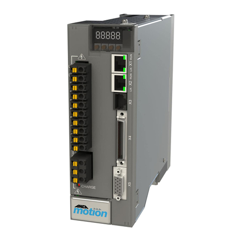
EA180 series servo drive is a high performance small and medium power AC servo unit developed by Shenzhen Sine Electric
Co.,Ltd. This series of products adopts advanced motor control special DSP chip, large scale programmable gate array (CPLD/FPGA)
and PIM power module, which has the characteristics of high integration, small volume, perfect protection and high reliability. The
optimized PID control algorithm realizes precise digital control of torque, position and speed, with high precision and fast response.
It provides advanced functions such as rigid selection, real-time automatic gain setting and automatic resonance suppression. Has
rich digital and analog interface, support MODBUS communication protocol, convenient networking. Two sub series respectively
support the use of 2500PPR incremental pulse encoder or Tamagawa 17 bit, 23 bit absolute incremental motor encoder with high
precision, to meet the different requirements of cost and performance. Can be widely used in CNC machine tools, printing and packaging
machinery, textile machinery, robotics, automated production lines and other automation fields.
EA180 series servo drive, there are two kinds of models that support EtherCAT bus and Canopen bus separately.
Because we have always been committed to the continuous improvement of product and product information, and therefore. The
information provided by our company is subject to change without notice.
For the latest changes and more,please visit www.sineedrive.com

EA180 Servo Drive Manual
2
Chapter 1 Product information
1.1 EA180 servo drive
1.1.1 Description of the nameplate
Model
Applicable motor size
Mains supply
Output
Barcode
S/N
Rated output current
EA180-8R4-3A
XXXXXX Software version
1.1.2Model Description
EA 180 E–8R4–3B-XX
EA:Servo drive
Product series
180:180 series
Interface
None:Analog pulse
C: Canopen
E:EtherCAT
Rated Output Current
1R6
1.6A
2R8
2.8A
5R5
5.5A
026
26A
Special Version
Encoder Type
A:Pulse incremental
B:Serial communi.
Mains Supply
1:1 phase 220V
2:1 or 3 phase 220V
3:3 phase 380V
Note: 1):AC220V voltage class, 7.6Aand below products, suitable for single-phase and three-phaseAC220V power supply, so there
is no special single-phase 220V products.
2): AC220V voltage class, 10A and above products, only to adapt to three-phase AC220V power supply varieties.
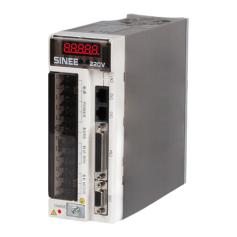
1.1.3Servo drive part name
L1C
L2C
L1
L2
L3
P+
D
C
U
V
W
CN1CN2CN3CN4CN5
SET
MOD
Display
Buttons
CHARGE
Bus volt.state
L1C、L2C
Control Circuit Supply
L1、L2、L3
Mains Supply
P+、
P+、D、C
External
Braking Resistor
CN5
Encoder Port
PE
5-bit 7-segment LED displays running state
Parameters setting
Show if the DC bus is in charging state, when the light is ON,even if
the mains supply is cut, the capacitor inside the drive is electrified.
Refer to the nameplate
Refer to the nameplate
DC bus voltage terminal,for DC bus sharing
Defaulted short-cut between P+ and D, when using external braking
resistor, remove the short-cut plate, open circuit in between P+ And D,
connect external braking resistor in between P+ And C.
To servo motor U、V、W
Connected to the encoder of the servo motor
Power and servo motor ground
Connected to upper computer
CN4
Control Terminal
CN2、CN3
Communi.Port Two in parallel connection,
include RS232、RS485、CAN interface
CN1 Analog
Monitoring Port Two analog output
U、V、W
Servo motor
CHARGE

EA180 Servo Drive Manual
3
1.1.4Block diagram of EA180 servo drive
Operation
panel
CN4
CN2/
CN3
CN1
CN5
M
encoder
Servo motor
rectifier
+
P
External braking resistor
Servo drive
Regenerative treatment circuit
IGBT module
U
V
W
IGBT drive
Protection
circuit
L1
L2
L3
Contrl.power
+15V
+5V
+3.3V
+24V
L1C
L2C
A/D
Position
control Speed
control Current
control
To DSP
PWM
DSP CPLD
From
protect.
circuit
Data Bus
External speed
External torque
Position pulse
A,B,Z output
Digital input
Digital output
Analog output
D/A
Current signal
treatment
A/D
Encoder signal
treatment
D C
Cooling fan
Mains supply
1 phase/ 3 phase
220V,
3 phase 380V
RS232
RS485
Built-in
braking
resistor
CHAR
GE
Electrolytic
capacitor
When 1-phase,
L3 not used

EA180 Servo Drive Manual
4
1.2 Servo motor
1.2.1 Description of the nameplate
Motor type
Rated output power Rated input voltage Rated current
Rated torque Rated speed Insulation class
Barcode and Serial number
Motor code Protection grade
Note: The actual wording on the nameplate may be different from above picture
1.2.2 Model Description
SER 08 - 0R7- 30- 2 A1
AY
2 3 4 6 75 8 9
-XX
10
1
①product series
②Motor flange size
③Rated motor output power
SER:standard servo motor
04:40mm
0R1:100W
SES:high performance servo
motor
06:60mm
0R2:200W
08:80mm
0R4:400W
09:86mm
0R7:750W
④Rated motor speed
11: 110mm
1R0:1000W
10:1000rpm
13:130mm
1R5:1500W
15:1500rpm
18:180mm
2R0:2000W
20:2000rpm
25:2500rpm
3R0:3000W
30:3000rpm
⑦Inertia type
4R5:4500W
A:Low inertia
5R6:5600W
⑤Voltage class
B:Medium inertia
7R5:7500W
011: 11000W
2:220V
C:High inertia
3:380V
⑨Optional
⑧Shaft end
Null:No option
⑥Encoder type
X: shaft without keyway
1:with brake(DC24V)
A:2500ppr
Y:Shaft with U-shaped slot and
screw hole
2:with oil seal
B:17bit incremental
C: 17 bit absolute
Z:Shaft with double-circle slot
and screw hole
3:with brake and oil sea
F:23bit absolute
⑩Special specifications
*: Some varieties may be double round keyway, but except the 130 flange motor, the width and height of the key are the same as
those of the U keyway. See Chapter 10.
The above 10 types of servo motor elements are not optional, please refer to the selection guide or consult
the company.

EA180 Servo Drive Manual
5
1.3 Confirm if the drive and motor matches with each other
1.3.1 Servo drive and motor matching table
Servo Drive
Servo Motor
Drive Model
Voltage
Size
Motor Model
Motor
Power
Rated
Speed
Rated
Torque
EA180-1R6-2□
Single phase or
three phase
AC220V
SIZEA
SES04-0R1-30-2□AY□
100W
3000rpm
0.32Nm
SER06-0R2-30-2□AY□
200W
3000rpm
0.64Nm
EA180-2R8-2□
SER06-0R4-30-2□AY□
400W
3000rpm
1.28Nm
EA180-5R5-2□
SER08-0R7-30-2□AY□
750W
3000rpm
2.38Nm
SER08-0R7-20-2□AY□
750W
2000rpm
3.58Nm
SER08-1R0-30-2□AY□
1000W
3000rpm
3.18Nm
EA180-7R6-2□
SIZEB
SER13-1R0-10-2□BY□
1000W
1000rpm
9.55Nm
SER13-1R0-20-2□BY□
1000W
2000rpm
4.77Nm
SER13-1R0-30-2□BY□
1000W
3000rpm
3.18Nm
EA180-010-2□
Three phase
AC220V
SER13-1R5-10-2□BY□
1500W
1000rpm
14.32Nm
SER13-1R5-20-2□BY□
1500W
2000rpm
7.16Nm
SER13-1R5-30-2□BY□
1500W
3000rpm
4.77Nm
EA180-8R4-3□
Three phase
AC380V
SER13-1R5-10-3□BY□
1500W
1000rpm
14.32Nm
EA180-5R4-3□
SER13-1R5-20-3□BY□
1500W
2000rpm
7.16Nm
SER13-1R5-30-3□BY□
1500W
3000rpm
4.77Nm
EA180-8R4-3□
SER13-2R0-20-3□BY□
2000W
2000rpm
9.55Nm
SER13-2R0-30-3□BY□
2000W
3000rpm
6.37Nm
EA180-012-3□
SER13-3R0-20-3□BY□
3000W
2000rpm
14.32Nm
SER13-3R0-30-3□BY□
3000W
3000rpm
9.55Nm
SER18-3R0-15-3BBZ□
3000W
1500rpm
19.1Nm
SER18-3R0-15-3BCZ□
3000W
1500rpm
19.1Nm
EA180-018-3B
SIZE C
SER18-4R5-15-3BBZ□
4500W
1500rpm
28.65Nm
EA180-021-3B
SER18-5R6-15-3BBZ□
5600W
1500rpm
35.65Nm
EA180-026-3B
SER18-7R5-15-3BBZ□
7500W
1500rpm
47.75Nm
Note that the type of encoder used by servo motors must be consistent with the type of encoder supported by the servo drive.
For more specifications of servo motors, please refer to our company.
1.3.2 Cables for encoders
Motor Flange Size
Encoder Type
Cable Model
40~80
2500ppr incremental encoder
A10-LP-A000-m*1
17bit incremental encoder
A10-LS-A000-m
17, 23bit absolute encoder
A10-LA-A000-m*2
110~180
2500ppr incremental encoder
A10-LP-H100-m
17bit incremental encoder
A10-LS-H100-m
17, 23bit absolute encoder
A10-LA-H100-m*2
Note *1:m indicates cable length, in meters
Note *2: battery for absolute encoder mounting on line cable. When the absolute encoder is used as incremental, use the 17bit
incremental encoder cable.
1.3.3Servo motor power cables / brake cables
Motor Flange Size
Motor Power Cable
Brake Cable (brake)
Motor power cable
Motor with a brake,brake cable
40~80
A10-LM-A010-m*1
-
A10-LZ-A005-m
110~130
A10-LM-H120-m
A10-LB-H120-m
-
180(3~4.5KW)
A10-LM-M220-m
-
Customer self-* 2
180(5.6~7.5KW)
A10-LM-M240-m
-
Customer-made
Note *1:m indicates cable length, in meters
Note *2: When 17 bit absolute encoder is used as incremental encoder, then please use 17bit incremental cable.

EA180 Servo Drive Manual
6
Chapter 2 Installation
2.1 Selection of braking resistor
When the output torque of the motor is in reverse direction, the energy is transmitted back from the load to the drive. This energy
will be injected into the capacitors of the bus bar, so that the voltage of the bus inside the drive rises, and the size of the recharging
energy depends on the inertia of the rotor and the load of the motor. If the system inertia is small, possibly through capacitor to drive the
internal recirculation of energy absorption, but if the system inertia is large, more than the capacity to absorb the energy, then the voltage
value may rise too high, causing the drive stop or even damage, so when the voltage rises to a certain value, the recharge energy must be
consumed by brake resistance.
The following table 2-1 lists the rotor inertia of the commonly used SER series servo motors and the capacity of the internal
absorption of EA180 servo drive, as well as the formula for the calculation of the regenerative energy.
Table 2-1 Rotor inertia of commonly used SER series servo motors and capacitor absorbable regenerative energy
Drive Model
Motor
Rotor Inertia
42
( 10 )J kg m
The regenerative energy from rated
speed to 0 with no load
Eo (Joule)
The maximum regenerative
energy of capacitor
Ec (Joule)
EA180-1R6-2□
SER04-0R1-30-2□AY
0.04
0.2
16
SER04-0R2-30-2□AY
0.18
0.89
16
EA180-2R8-2□
SER06-0R4-30-2□AY
0.3
1.48
24
EA180-5R5-2□
SER08-0R7-30-2□AY
1.01
4.99
24
EA180-7R6-2□
SER13-1R0-10-2□BY
17.14
9.42
41
EA180-7R6-2□
SER13-1R0-20-2□BY
8.71
19.1
41
EA180-010-2□
SER13-1R5-20-2□BY
12.08
26.5
41
EA180-5R4-3□
SER13-1R5-20-3□BY
12.08
26.5
34
EA180-8R4-3□
SER13-2R0-20-3□BY
17.14
37.67
49.6
EA180-012-3□
SER13-3R0-20-3□BY
25.58
56.22
49.6
EA180-018-3B
SER13-4R5-15-3BBZ
45.51
56.26
61.2
EA180-021-3B
SER13-5R6-15-3BBZ
79.89
98.76
91.8
EA180-026-3B
SER13-7R5-15-3BBZ
102.36
126.54
91.8
Calculation formula of regenerative energy:
2
182
JV
Eo
(Joule)V:rpm,motor’s rated speed
The difference in rotor inertia between a servomotor with a brake and a servomotor without a brake is little, and can be
considered the same.
2.2 Built in braking resistor
EA180 series drive starting from 5R5 contains a braking resistor that is suitable for general load inertia. Table 2-2 is the
specifications for EA180 series built-in brake resistors.
Table 2-2 EA180 Built in brake resistance and Allowable minimum external resistance
Servo drive model
Built in brake resistor specifications
Built in brake resistance,
handling capacity
Allowable minimum
external resistance
Resistance (P8-10)
Capacity (P8-11)
EA180-1R6-2□
N/A
N/A
N/A
50Ω
EA180-2R8-2□
N/A
N/A
N/A
50Ω
EA180-5R5-2□
50Ω
100W
50W
50Ω
EA180-7R6-2□
50Ω
100W
50W
40Ω
EA180-010-2□
50Ω
100W
50W
40Ω
EA180-5R4-3□
50Ω
100W
50W
50Ω
EA180-8R4-3□
50Ω
100W
50W
50Ω
EA180-012-3□
50Ω
100W
50W
45Ω
EA180-018-3B
40Ω
200W
90W
30Ω
EA180-021-3B
40Ω
200W
90W
30Ω
EA180-026-3B
40Ω
200W
90W
25Ω
2.2.1 External braking resistance capacity calculation formula
When the regenerative capacity exceeds the handling capacity of the built in braking resistance, alarm Al017 occurs, should
apply to external braking resistance.
According to the calculation formula of the retrogradation of energy, assuming total load inertia is N times the inertia of the
rotor of the motor, brake motor is braked from the rated speed to 0, regenerative energy is N *Eo, the action cycle is T(S),
then, the power of brake resistance= 2[Nx Eo-Ec]/T

EA180 Servo Drive Manual
7
Chapter 3 Wiring
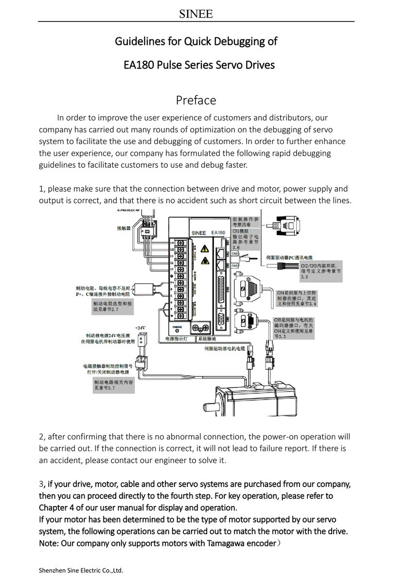
3.1 Peripherals connection
CN2
CN3
When braking resistor and
bus capacitor is not enough,
P+、C connected to external
braking resistor.
+24V
The electromagnetic contactor
brake control signal turns on /
off the brake power supply
EMI filter
Brake supply 24V is applied
when the servo motor has brake. ground
Servo drive, PC
communication cable
Power cable
Contactor
Servo motor
3-phase 220VAC/380VAC
breaker
power
L1C
L2C
L1
L2
L3
P+
D
C
U
V
W
CHARGE
电源 POWER 直流母线 制动 BRK 电机 MOTOR
CN1CN2CN3CN4CN5
SINEE EA130A
EA180
Precautions:
1) Servo drives are directly connected to industrial power supplies without the use of transformers. To prevent cross - electric shock
in the servo system, use a fuse or wiring breaker on the input power supply.
2) No electromagnetic contactor is installed between the drive and the motor, which will cause the drive to be damaged.
3) External control power supply and 24V supply, please check the power supply capacity, especially when several drives or brake
are supplied in the same time, if the power supply capacity is not enough, it will cause the current supply shortage, drive or brake
damage.
4) Please note that the brake power supply is 24V DC, and its capacity shall comply with the power requirements of the brake. For
braking power, refer to servo motors.
5) Confirm the servo motor output U, V, W terminals phase sequence connection is correct, wrong wiring may cause the motor does
not turn or disorderly turn, and then alarm appears, and even lead to motor damage.
6) If the use of external resistor, the P+ and D terminals are in open circuit, external brake resistor is connected to terminal P+, C, if
the use of internal braking resistance,terminals P+ and D are required to be short,and terminals P+, C are open (see Section 2.7).
7) in the single-phase 220V wiring, the main power supply terminals are L1, L2, the vacated terminal L3 should not be wiring.
8) CN2 and CN3 are two pins defined exactly the same communication interface, which can be used arbitrarily between the two.

EA180 Servo Drive Manual
8
3.2 Main circuit terminal connection
The main circuit (high voltage part) terminal arrangement and screw dimensions are as follows.
L1C
L2C
L1
L2
L3
P+
D
C
U
V
W
Drive size
Main circuit terminals
Screw size
Torque
SIZE A
M4
2.5N.m
SIZE B
M4
2.5N.m
SIZE C
M4
2.5N.m
Drive size
PE ground terminal
Screw size
Torque
SIZE A
M4
2.5N.m
SIZE B
M4
2.5N.m
SIZE C
M4
2.5N.m
3.2.2The main circuit (high voltage part) terminal description
Table 3-1 Description of main circuit terminal of servo drive
Terminal mark
Name
Terminal function
L1C、L2C
Control power input terminal
1-phase input voltage class is the same as the main circuit power
L1、L2、L3
Main circuit AC power
input terminal
EA180-1R6-2□
EA180-2R8-2□
EA180-5R5-2□
EA180-7R6-2□
L1、L2 1-phase 220V input
Or L1、L2、L3 3-phase 220V input
EA180-010-2□
L1、L2、L3 3-phase 220V input
EA180-5R4-3□
EA180-□□□-3□
EA180-026-3□
3-phase 380V input
P+、D、C
External braking resistor
connection terminal
The default connection between P+ and D is short wiring. When the braking
capacity is insufficient, please open the circuit between P+ and D, and
connect the external braking resistor between P+ and C.
P+、
Common DC bus terminal
The DC bus terminal of the servo drive can be connected in parallel when
the multiple drives are in operation.
U、V、W
Servo motor
connection terminal
The connecting terminals of the servo motors are connected with U, V and
W of the motor.
PE
Ground
EA180-2R8-2□、EA180-5R5-2□ one ground terminal; connect with the two
ground terminals of other power size, power supply and motor ground
terminal.
3.2.3Power connection
Servo drive power supply wiring method is divided into single-phase and three-phase respectively, single-phase only suitable
for the output current of 7.6A and below models.
Single phase power supply wiring method (rated output current 7.6A and below applicable)
Figure 3-1 1-phase power supply connection

EA180 Servo Drive Manual
9
Three phase power supply wiring method (all series are applicable)
3-phase power supply connection
Note☞
1. 1. if you do not want to cut off the main loop power supply when a fault occurs, you do not need to use the RA
relay.
2. 2., L1C, L2C can also be not used with external power supply, but they are connected to P+ - - terminals (No
need to distingh polarity).
3.2.4 Power on timing sequence
Control circuit supply
Main circuit supply
Servo ready output
S-RDY)
Servo enabled
S-ON)
Servo motor excitation
Power off
power on
Power off
power on
Power off ready
enabled void
command not received
motor power off motor power on
command not received
command received
Position/speed/torque
command
delay 1.5S
delay P0-16time
Servo enabled signal
S-ON signal) void valid void
enabled void
motor power off
enabled valid
Figure 3-3 Power-on timing diagram
For power connections, refer to Figure s 3-1 and 3-2 and turn on the power supply in the following order:
1) the power supply L1C and L2C of the control circuit must be connected in the same time or before the main loop supply is
connected. If the power of the control circuit is connected only, the servo ready signal (S-RDY) will not be effective.
2) the power supply is connected to the main circuit power input terminal (three-phase connected L1, L2, L3, single phase L1 and
L2) by electromagnetic contactor.
3) when the main circuit is connected, the delay time is about 1.5 seconds, and the servo ready signal (SRDY) is effective and
receive the servo enabled signal (S-ON) at this time. When the servo enable signal is detected, the motor is excited and in the running
state. If the servo is disabled or has an alarm, the drive output is switched off and the motor is in a free state.
4) when the servo is switched on with the power supply, the motor is excited about 1.5 seconds later.
5) frequent switching on and off the main circuit power, may damage the soft start circuit and the energy consumption brake circuit,
the frequency of switching on is best limited to 5 times per hour, 30 times a day below. If the drive unit or the motor is overheating, after
the cause of the failure is ruled out, reconnect the power supply after 30 minutes of cooling.
6) Do not connect the input power line to the output terminals U, V, and W, otherwise it will damage the servo drive.
7) the braking resistance is absolutely prohibited from connecting between the DC bus P+ and the terminals, otherwise it may cause
a fire.
8) after the power is switched off, there may be residual voltage on the internal capacitor of the servo drive. Please confirm that the
CHARGE indicator on the servo driver panel is extinguished before checking the operation.
Specification for connector of motor power cable

EA180 Servo Drive Manual
10
Table 3-2 Servo motor power cable and servo motor connecting terminal
Connector shape and type
Terminal pin distribution
Motor flange
12
34
Shell type:172159-1 TE MATE-N-LOCK
Insert spring type:794407-4 TE MATE-N-LOCK
4PINAmp plug (excluding brake)
Pin#
function
1
U
2
V
3
W
4
PE
40
60
80
86
1
4
3
2
Model:YDA28K4TS
Air plug (excluding brake)
Pin#
function
1
PE
2
U
3
V
4
W
110
130
7
6
5
4
3
2
1
Model:YDA28K7TS
Air plug (including brake)
Pin#
function
1
PE
2
U
3
V
4
W
5
24V(brake)
6
0V(brake)
7
none
110
130
Model:MS3108F32-17S
Air plug
Pin#
function
A
U
B
V
C
W
D
PE
180
Note ☞
1. For 40, 60, 80, 86 flange with brake, the brake power is independent 2P amp head, without distinguishing the polarity.
2. For 180 flange with brake, the brake power plug is used with MS3106A10SL-4S, without distinguishing the polarity.
3. The graph drawn in the table is the cable end。
3.2.5Recommended specifications for main circuit connection cables
Drive model
L1C,L2C
L1,L2,L3
P+,C
U,V,W
PE
EA180-1R6-2□
0.5mm2
0.5mm2
0.5mm2
0.5mm2
1.0mm2
EA180-2R8-2□
1.0mm2
1.0mm2
1.0mm2
2.5mm2
or above
EA180-5R5-2□
EA180-7R6-2□
2.0mm2
2.0mm2
2.0mm2
EA180-010-2□
EA180-5R4-3□
1.0mm2
1.0mm2
1.0mm2
EA180-8R4-3□
2.0mm2
2.0mm2
2.0mm2
EA180-012-3□
EA180-018-3B
4.0mm2
4.0mm2
4.0mm2
EA180-021-3B
EA180-026-3B
6.0mm2
6.0mm2
6.0mm2

EA180 Servo Drive Manual
11
3.3 CN5 Encoder signal terminal
3.3.1. CN5 is the encoder signal terminal, which is DB15 socket, and its position is shown in Figure 3-4:
1
2
3
4
5
6
7
8
9
10
11
12
13
14
15
SINEE EA100
L1C
L2C
L1
L2
L3
P+
D
C
U
V
W
CHARGE
电源 POWER 直流母线 制动 BRK 电机 MOTOR
CN1CN2CN3CN4CN5
EA180
Figure 3-4 CN5 terminal location
3.3.2Drive side encoder terminal definition
5
10
4
9
3
8
2
7
1
15
14
13
12
11
6
encoder B+ signal
encoder B- signal
encoder A+ signal
encoder A- signal
shielded layer
connected to PE
encoder Z- signal
encoder U- signal
encoder V- signal
encoder W- signal
encoder supply 5V
encoder Z+ signal
encoder U+ signal
encoder V+ signal
encoder W+ signal
GND 5
10
4
9
3
8
2
7
1
15
14
13
12
11
6
shielded layer
connected to PE
encoder supply 5V
SD+
SD-
GND
CN5 incrementalencoder terminals CN5 17-bit encoder terminals
-Indicates that the
terminal is suspended,
please do not connect
Note: when connected to fewer
wires encoder, U+/U-, V+/V-,
W+/W-, do not connect.
Figure 3-5 CN5 terminal pin distribution
2KΩ
100Ω
100Ω
1
33
34
上位机装置
100Ω
100Ω
31
32
14
16
PULSE+
PULSE-
SIGN+
SIGN-
GND
PE
GND
GND
伺服驱动器
普通脉冲位置指令
最小脉冲宽度1us
最大输入频率为500kpps
PULHIP
PULHIS
1
6
11
5
10
15
Figure 3-6 CN5 pins location
3.3.3Servo motor side encoder terminal definition
The servo motor side has two types of encoder terminals
The aviation plug adapter: motor flange 110 and above is applicable, the pin definition is shown in table 3-4a and 4b
Cable end
Motor end
2
5
14
13
15
11
10
6
3
1
Terminal model:YDA28K15TS
12
10
53
11
13
14
6
15

EA180 Servo Drive Manual
12
*:For motors with flanges 110 and above, all encoders use the same plug, but pin definitions different only.
The amp plug adapter: for motor flange 86 and below, pin definition refer to table 3-4a, 4b
Motor-end connector
Appearance
2500ppr incremental encoder
17-bit encoder
4 532
1
9 107
6
14 151312
11
8
Motor-end
321
64
987
5
Motor-end
Cable-end connector
15
610
11
15
234
9 7
12
1314
8
Cable-end
123
6 4
7
89
5
Cable-end
Table 3-4a 17/23bit incremental/absolute encoder pin#
*:The VB+ and VB- signals are used by absolute encoders only, the incremental encoder does not have the two signals and the
corresponding pins.
Table 3-4b 2500ppr encoder pin#
Function
DB15 on drive side
Motor side
AMP plug
AIR plug
Signal code
Pin #
Pin #
Pin #
Encoder Z+
Z+
1
7
6
Encoder U+
U+
2
6
10
Encoder V+
V+
3
10
11
Encoder W+
W+
4
11
12
Encoder power 5V
+5V
5
2
2
Encoder Z-
Z-
6
5
9
Encoder U-
U-
7
8
13
Encoder V-
V-
8
12
14
Encoder W-
W-
9
15
15
Encoder ground
GND
10
3
3
Encoder B+
B+
11
4
5
Encoder B-
B-
12
14
8
Encoder A+
A+
13
9
4
Encoder A-
A-
14
13
7
Shied PE
PE
Housing
1
3
Encoder wiring notes:
1) Make sure that the drive side and the motor side shield layer reliably grounding, otherwise it will cause a drive alarm.
2) Please pay special attention to the connection of GND and PE, and the combination of the two types of encoders and
connectors, there are different ways of connection.
3) Please make sure that the differential signal corresponding to the two core wires in the connecting twisted pair. For example,
A+ and A- are used as a set of differential signals, and a pair of twisted pairs should be used.
Function
DB15 on drive side
Motor side
AMP plug
AIR plug
Signal code
Pin #
Pin #
Pin #
encoder power
+5V
5
1
2
encoder ground
GND
10
2
3
serial signal +
SD+
1
5
4
serial signal -
SD-
3
6
7
external battery +
VB+
7
14
external battery -
VB-
8
15
Shied PE
PE
Housing
2
3

EA180 Servo Drive Manual
13
4) When using a 17/23bit encoder, if the wire length is below 5 meters, the wire cross-sectional area is 0.2mm2. If more than 5
meters, each increase of 1 meters, the core cross sectional area should be increased by 0.05mm2.

EA180 Servo Drive Manual
14
3.4 CN4 connector
3.4.1 The CN4 signal terminal provides the signal needed for connection with the upper controller. Here below is the DB44 plug, pin
distribution and signal definition.
SINEE EA100
L1C
L2C
L1
L2
L3
P+
D
C
U
V
W
CHARGE
POWER DC BRK MOTOR
EA180
Figure 3-7 CN4 pins location and definition
3.4.2CN4 pins location and definition
Signal
Pin #
Description
Digital input
DI1
5
Digital input, the default function number is 1
DI2
20
Digital input, the default function number is 2
DI3
4
Digital input, the default function number is 13
DI4
19
Digital input, the default function number is 14
DI5
3
Digital input, the default function number is 3
DI6
18
Digital input, the default function number is 12
DI7
2
Digital input, the default function number is 20
DI8
17
Digital input, the default function number is 21
COM+
21
Digital input common terminal (+)
Supply
+24V
25/40
Internal 24V power supply, voltage range +20V to 26V, maximum output current 200mA
COM
7/22/36
Internal 24V power ground; digital input common ground
+5V
6
+5V power supply with maximum output current of 50mA
-
44
Reserved( for +10V or other purposes later )
GND
29
+5V power ground
Digital output
DO1
8
Digital output, the default function number is 1
DO1-
37
DO2
23
Digital output, the default function number is 2
DO2-
38
DO3
9
Digital output, the default function number is 8
DO3-
39
DO4
24
Digital output, fixed function number is 12
DO4-
10
-
41
Not used
Position pulse
input
PULHIP
1
the positive end when command pulse is used with 24V suply
PULSE+
33
Position pulse command +
PULSE-
34
Position pulse command +
PULHIS
16
the positive end when command pulse is used with 24V suply
SIGN+
31
Position direction instruction +

EA180 Servo Drive Manual
15
Signal
Pin #
Description
SIGN-
32
Position direction instruction -
Freq. diverting
output
PA+
28
A pulse differential frequency division output, maximum allowable current 20mA
PA-
13
PB+
12
B pulse differential frequency division output, maximum allowable current 20mA
PB-
27
PZ+
11
B pulse differential frequency division output, maximum allowable current 20mA
PZ-
26
OCZ
35
Z pulse open collector output with maximum permissible current 40mA.
GND
14
Analog input
AI1
15
Analog input 1
AI2
30
Analog input 2
GND
29
Analog input signal ground
Note☞
All GND terminals are connected within the drive, and all COM terminals are connected within the drive
3.4.3(DI)Digial Input function
Value
Name
Function
Description
Triggering
mode
Running
mode
0
Disabled
Terminal invalid
1
S-ON
Servo enabled
ON:enabled
OFF:disenabled
Level
P S T
2
ALM-RST
Alarm and fault reset
OFF→ON:resettable fault reset
Edge
P S T
3
P-CLR
Position error clear
Edge/Level
P
4
DIR-SEL
Speed direction selection
ON:negative speed
command direction
OFF:the setting speed
direction
Level
S
5
CMD0
Internal command bit0
In the multi preset position control mode, the signal is
multi position switching function;
In the multi preset speed control mode, the signal is a
multi speed switching function;
Level
P S
6
CMD1
Internal command bit1
Level
P S
7
CMD2
Internal command bit2
Level
P S
8
CMD3
Internal command bit3
Level
P S
9
CTRG
Internal command trigger
multiple position trigger
Edge
P
10
MSEL
Control mode switched
Level
P S T
11
ZCLAMP
zero speed clamp enabled
ON:enabled
OFF:disenabled
Level
S
12
INHIBIT
Pulse inhibit
ON-inhibt
OFF:pulse input allowed
Level
P
13
P-OT
inhibit positive drive
ON-inhibit
OFF-allowed
Level
P S T
14
N-OT
Inhibit negative drive
ON-inhibit negative drive
OFF-allowed negative
drive
Level
P S T
15
GAIN_SEL
Gain switched
ON:use second gain
OFF:use first gain
Level
P S T
16
J_SEL
Inertia switched
ON:use second inertia ratio P4-11
OFF:use first inertia ratioP4-10
Level
P S T
17
JOG_P
Positive jog
ON:postive jog
OFF:no function
Level
S
18
JOG_N
Negative jog
ON:negative inching
operation
OFF:no function
Level
S
19
TDIR-SEL
Torque command direction
selection
ON:negative torque
command
OFF:the setting torque
direction
Level
T
20
GNUM0
Electronic gear ratio numerator
selection 0
GNUM1
GNUM0
Code
0
0
P1-04
0
1
P1-08
1
0
P1-10
1
1
P1-12
Level
P
21
GNUM1
Electronic gear ratio numerator
selection 1
Level
P
22
ORGP
External detector input
Rising edge: external detector is valid
Falling edge: external detector is invalid
Edge
P S T
23
SHOM
Homing
OFF→ON: Homing starts
Edge
P S T
24
TL2
External torque limiting
ON- External torque limiting enable
OFF- External torque limiting is prohibited
Level
P S T
25
EMGS
Emergency stop
ON:emergency stop
OFF:no function
Level
P S T
33
TDIR-SEL
Position command direction
selection
ON: negative position
command direction
OFF: the setting command
direction
Level
P

EA180 Servo Drive Manual
16
3.4.4Digital output function definition( DO)
Value
Name
Function
Description
Running
mode
0
Disable
Terminal invalid
1
S-RDY
Servo ready
Effective- servo ready to receive S-ON command
Invalid - the servo is not ready and does not receive the S-ON
command
P S T
2
BK
Brake control
Effective-brake disengaged
Invalid-brake engaged
P S T
3
TGON
Motor rotation
Effective - the motor is rotating (RPM is higher than the P0-04 setting)
Invalid - motor stop rotating (speed below P0-04 setting)
P S T
4
ZER0
Motor 0 speed
Effective - motor speed is zero (speed lower than P0-03 setting)
Invalid - motor speed is not zero (RPM is higher than P0-03 setting)
P S T
5
V-CLS
Speed close
Effective: when in speed control, the actual speed of the motor reaches
or exceeds the setting value of the P2-08 (regardless of direction).
S
6
V-CMP
Speed comparison
Effective: When in speed control, the absolute difference between the
actual speed and the speed of the motor is less than P2-09
S
7
PNEAR
Position near
Effective: In position control mode, the position deviation pulse is less
than the setting value of the positioning approach width P1-23
P
8
COIN
Positioning finishes
Effective: In position control mode, the position deviation pulse is less
than the positioning completion width, the P1-24 setting value, and the
condition of the P1-22 definition is satisfied.
P
9
C-LT
Torque limiting
Effective: motor torque limited
Invalid: motor torque is not limited
P S
10
V-LT
Speed limiting
Effective: motor speed is limited
Invalid: motor speed is not limited
T
11
WARN
Warning output
Effective: warning happens
P S T
12
ALM
fault output
Effective: fault happens
P S T
13
Tcmp
Torque compliance
Effective: motor output torque reaches set point
Invalid: motor output torque is not up to set point
T
14
Home
Homing
Effective: Homing finishes
Invalid: Homing is in the process
P S T
3.4.5Digital input terminal connection
The digital (DI) input terminal of the EA180 series servo drive uses a full bridge rectifier circuit. The current flowing through the
terminals can be either positive (NPN mode) or negative (PNP mode).
Taking DI1 as an example, the interface circuit of DI1 ~ DI8 is identical.
1) When the upper device is the relay output:
4.7K
+24V
+24V supply
COM+
DI1
relay
COM
Internal 24V supply
4.7K
+24V
+24V supply
COM+
DI1
relay
COM
External 24V supply
DC24V
4.7K
+24V
+24V supply
COM+
DI1
COM
Servo drive Servo drive
Not use 1-phase power
25
21
5
7
25
21
5
7
25
21
5
7
relay
DC24V
Figure 3-8 when the upper device is relay output, digital input terminals wiring
Note☞
Defaulted setting:
The COM terminal used pin #7 , pin# 22/36 is also applicable.
The GND terminal used pin #14, also pin# 29 is applicable.
The servo internal +24V used pin# 25, also pin # 40 is applicable.

EA180 Servo Drive Manual
17
2) As for NPN open collector circuit output:
4.7K
+24V
+24V supply
COM+
DI1
COM
Internal 24V supply Servo drive
NPN
NPN
4.7K
+24V
+24V supply
COM+
DI1
COM
External 24V supply Servo drive
NPN
NPN
DC24V
25
21
5
7
25
21
5
7
Figure 3-9(a) NPN open collector circuit output wiring diagram
3) As for PNP open collector circuit output:
4.7K
+24V
+24V supply
COM+
DI1
COM
Internal 24V supply Servo drive
PNP
PNP
4.7K
+24V
+24V supply
COM+
DI1
COM
External 24V supply Servo drive
PNP
PNP
DC24V
25
21
5
7
25
21
5
7
Figure 3-9(b) PNP open collector circuit output wiring diagram
Note☞
1. When using external power supply, please make sure 24V and COM+ are in open circuit.
2. Do not support PNP and NPN mixed input
3.4.6Digital output terminal connection
Taking DO1 as an example, the interface circuit of DO1 ~ DO4 is identical.
1) When the upper device is relay:
DC5V~24V
NPN
r
e
l
a
y
Servo drive
DO1
DO1-
8
37
Internal supply
25 +24V
COM
22
NPN
r
e
l
a
y
Servo drive
DO1
DO1-
8
37
25
22
External supply
NPN
DC5V~24V
DO1
DO1-
No relay
8
37
25
22
NPN
relay
Servo drive
DO1
DO1-
8
37
25 +24V
COM
22
fly-wheel diode
polarity error
Servo drive
Figure 3-10(a) Relay input, the correct DO terminal wiring
Figure 3-10(b) Relay input, the wrong DO wiring
Note☞
When the upper device is a relay input, be sure to access the fry-wheel diode, otherwise it may damage the DO port

EA180 Servo Drive Manual
18
2) When the uppder device is optocoupler input
NPN
DC5V~24V
Servo drive
DO1
DO1-
8
37
NPN
Servo drive
DO1
DO1-
8
37
Internal supply External supply
25 +24V
COM
22
25
COM
22 External
supply
ground
NPN
DC5V~24V
Servo drive
DO1
DO1-
8
37
NPN
DO1
DO1-
8
37
Internal supply External supply
25 +24V
COM
22
25
COM
22
No current
limiting resistor No current
limiting
resistor
External
supply
ground
Servo drive
Figure 3-11(a)Optocoupler input, correct DO port wiring
Figure 3-11(b)Optocoupler input, wrong DO port wiring
Note☞
Servo drive internal optocoupler output circuit, maximum allowable voltage and current capacity are as follows:
voltage:DC30V(max.)
current:DC50mA(max)
As for inductive loads (e.g. relays and Contactors), should be equipped with surge absorption circuit; such as: RC
absorption circuit (note the leakage current shall be less than that of the control contactor or relay current), varistors,
or diode etc. (for DC magnetic circuit, must pay attention to the polarity when installing). The component of the
absorption circuit is to be mounted near the coil of the relay or contactor.
3.4.7CN4 analog input terminal wiring
Signal
Code
Pin #
Function
Analog
AI1
15
Voltage analog input
Voltage input range: -10V to +10V, resolution 12 bits
Maximum allowable voltage: ±12V
Input impedance: 10K
AI2
30
GND
29
Analog input ground
AI1、AI2 is generally used for speed or torque analog signal input.
-10~+10V AI1
-10~+10V AI2
About 9K
About 9K
Servo drive
GND
15
30
29
Figure 3-12 AI1、AI2 terminal wiring
3.4.8CN4 position command input signal
The position command pulse input signal and the command symbol input signal terminal in CN4 terminal are described below.
Table 3-6 Position pulse input signal description
Signal
Pin #
Function
Position
command
PULSE+
33
Pulse command input mode:
Differential input
Open collector input
Input pulse mode:
Direction + pulse
A and B phase orthogonal pulses
CW/CCW pulse
PULSE-
34
SIGN+
31
SIGN-
32
PULHIP
1
Command pulse external power input interface
PULHIS
16
+24V
25/40
24V +
COM
36
24V ground

EA180 Servo Drive Manual
19
The pulse command can be input by an open collector circuit or a differential mode. The maximum input pulse frequency of the
differential input mode is 500Kpps, and the maximum input pulse frequency of the open collector circuit is 200Kpps.
The pulse input terminal needs to set a certain filtering time to prevent the interference signal from entering the servo drive, resulting
in misoperation of the motor. For filtering time, see the description of P1-15 function parameters.
Different command input pulse patterns have different timing and time parameters
Table 3-7 Timing table for different command pulses
Pulse command mode
Logic state
Pulse waveform
Pulse + direction
P1-01=0
positive logic
PULSE
SIGN T3
T2
forward reverse
T1
P1-01=1
negative logic
PULSE
SIGN T3
T2
forward reverse
T1
Two-phase orthogonal pulse
(4 octave)
P1-01=2
positive logic
PULSE
SIGN
T4 T4
forward
T4 T4
reverse
P1-01=3
negative logic
reverse
PULSE
SIGN
T4 T4
T4
T4
forward
CW + CCW pulse
P1-01=4
positive logic
PULSE
SIGN
T3
T1
T2
forward reverse
P1-01=5
negative logic
forward reverse
PULSE
SIGN
T3
T1
T2
Table 3-8 Pulse input time parameter
Pulse mode
Maximum input
frequency
The minimum allowable width
Voltage
T1
T2
T3
T4
Differential
500Kpps
2
5V
Open collector
200Kpps
24V(MAX)

EA180 Servo Drive Manual
20
3.4.8.1 Position command pulse differential input mode
Servo drive
2KΩ
100Ω
100Ω
1
33
34
Upper Computer
100Ω
100Ω
31
32
41
16
GND
PULSE+
PULSE-
SIGN+
SIGN-
Minimum pulse width
of pulse position
command 1US
The maximum input
frequency is 500kpps
PE
GND
2KΩ
Figure 3-13 Differential mode input pulse command wiring diagram
Note☞
Please ensure "2.8V≤ (H level -L level) ≤3.7V", otherwise the servo drive input pulse will be unstable. It will result in
the following situations::
在Pulse loss occurs when the instruction pulse is input.
AnCommand reversal occurs when the command direction is input.
3.4.8.2 Position command pulse open collector input mode
When using internal 24V power supply
2KΩ
100Ω
100Ω
1
33
34
100Ω
100Ω
31
32
36
16
PULSE-
SIGN-
COM
+24V
PULHIP
PULHIS
+24V Servo drive
PULSE+
PE
Internal 24V supply NPN connection Internal 24V supply PNP connection
Open collector pulse position
command
The maximum input
frequency is 200kpps
Minimum pulse width 2.5us
25
2KΩ
SIGN+
2KΩ
100Ω
100Ω
1
33
34
100Ω
100Ω
31
32
36
16
PULSE-
SIGN-
COM
+24V
PULHIP
PULHIS
+24V Servo drive
PULSE+
PE
25
2KΩ
SIGN+
Figure 3-14 open collector pulse input command wiring diagram (using the servo internal 24V)
Other manuals for EA180 Series
2
This manual suits for next models
1
Table of contents
Other Sinee Servo Drive manuals
Popular Servo Drive manuals by other brands
Kollmorgen
Kollmorgen AKD series installation manual
Siemens
Siemens SIMOREG DC Master 6RA7028-6DS22 operating instructions
Motor Power Company
Motor Power Company DMR 50-5/50 V3.0 installation guide
BLUM
BLUM AVENTOS Original Installation Instructions
Moog
Moog Class 5 SmartMotor Guide
Baldor
Baldor MicroFlex e100 quick start guide
Panasonic
Panasonic MINAS-A4N Reference Specifications
Cowlacious Designs
Cowlacious Designs Scary Terry ST-400 Operation manual

YASKAWA
YASKAWA USAREM-A5A Bulletin

SEW-Eurodrive
SEW-Eurodrive DR Series operating instructions
Harmonic Drive
Harmonic Drive HA-675 Series manual
Delta
Delta ASDA-A3 Series user manual

