Sinexcel PDS1-750K-H User manual

PDS1-750K-H DC converter
Manual

1
Sinexcel
PDS1-750K-H DC converter
User Manual
Data Version V1.0
Filed on 2022-06
Shenzhen Sinexcel Electric Co., Ltd.
All rights reserved. In case of any content change, it shall be without prior notice.
Shenzhen Sinexcel Electric Co., Ltd.
Website: http://sinexcel.us/ or www.sinexcel.com
Add: Building 6, Area 2, Baiwangxin High-tech Industrial Park, No. 1002, Songbai Road, Nanshan District,
Shenzhen
Postcode: 518055
Hotline: +86 0755-8651-1588

2
Table of Contents
1 OVERVIEW.................................................................................................................................................................5
1.1APPLICABLE MODELS.......................................................................................................................................................5
1.2 TARGET GROUP ...............................................................................................................................................................5
1.3 NOMENCLATURE TERMS AND ABBREVIATIONS ................................................................................................................6
2 SAFETY PRECAUTIONS...........................................................................................................................................7
2.1 SYMBOLS.........................................................................................................................................................................7
2.2 IMPORTANT SAFETY INSTRUCTIONS.................................................................................................................................7
2.3ADDITIONAL INFORMATION .............................................................................................................................................8
3 PRODUCT INTRODUCTION ....................................................................................................................................9
3.1 SYSTEM INTRODUCTION..................................................................................................................................................9
3.2 BIDIRECTIONAL DC CONVERTER APPEARANCE...............................................................................................................9
3.3 SYSTEM SCHEMATIC ......................................................................................................................................................10
3.4 MODULE INTRODUCTION...............................................................................................................................................11
3.5 DIMENSIONS AND WEIGHT ............................................................................................................................................12
3.6 HEAT DISSIPATION AND FIRE PROTECTION......................................................................................................................13
3.7 SWITCH STATUS .............................................................................................................................................................13
4 SPECIFICATIONS ....................................................................................................................................................14
5 STORING、LIFTING AND TRANSPORTING.......................................................................................................15
5.1 TRANSPORTAND STORAGE.............................................................................................................................................15
5.2 TRANSFER .....................................................................................................................................................................16
5.3 OUT OF THE BOX INSPECTION.........................................................................................................................................18
5.3.1 Unpacking .............................................................................................................................................................18
5.3.2 Test.........................................................................................................................................................................18
6 DEVICE INSTALLATION........................................................................................................................................20
6.1 INSTALLATION REQUIREMENTS ......................................................................................................................................20
6.1.1 Basic requirements ................................................................................................................................................20
6.1.2 Outdoor requirements............................................................................................................................................20
6.1.3 Foundation Support Requirements........................................................................................................................21
6.1.4 Space requirements................................................................................................................................................21
6.1.5 Ventilation Requirements.......................................................................................................................................22
6.2 ON-SITE INSTALLATION..................................................................................................................................................23
6.2.1 Trunking design.....................................................................................................................................................23
6.2.2 Fixed DC Converter ..............................................................................................................................................24
6.3 ELECTRICAL CONNECTIONS ...........................................................................................................................................25
6.3.1 General Safety.......................................................................................................................................................25
6.3.2 Installation tool .....................................................................................................................................................25
6.3.3 Wiring Parts ..........................................................................................................................................................26
6.3.4 Preparation before wiring .....................................................................................................................................26
6.3.5 Cable Requirements...............................................................................................................................................27

3
6.3.6 Wiring Precautions................................................................................................................................................28
6.3.7 Overview of the wiring area ..................................................................................................................................28
6.3.8 Power line wiring..................................................................................................................................................30
6.3.9 Ground connection................................................................................................................................................31
6.3.10 Installation Checklist...........................................................................................................................................32
7 PRODUCT RUNS ......................................................................................................................................................33
7.1 CHECK BEFORE RUNNING ..............................................................................................................................................33
7.1.1 Check cable connections .......................................................................................................................................33
7.2.2 Check the DC converter ........................................................................................................................................33
7.2.3 Check battery/bus side voltage..............................................................................................................................34
7.2 START AND STOP............................................................................................................................................................34
7.2.1 Start.......................................................................................................................................................................34
7.2.2 Stop........................................................................................................................................................................35
7.3 OPERATING MODE..........................................................................................................................................................36
7.3.1 Main function ........................................................................................................................................................36
7.3.2 Introduction to work status....................................................................................................................................37
7.4 PROTECTIVE FUNCTION .................................................................................................................................................38
8 LCD TOUCH SCREEN OPERATION GUIDE ........................................................................................................39
8.1 LCD TOUCH SCREEN FUNCTION AND MENU INTRODUCTION ..........................................................................................39
8.2 MAIN PAGE INTRODUCTION ...........................................................................................................................................40
8.2.1 Start page ..............................................................................................................................................................40
8.2.2 Home page.............................................................................................................................................................40
8.3 OPERATION INFORMATION MENU INTRODUCTIO.............................................................................................................41
8.4 INTRODUCING THE EVENT LOG MENU...........................................................................................................................42
8.5 CONTROL SCHEDULING MENU INTRODUCTION...............................................................................................................44
8.6 SYSTEM SETTINGS MENU INTRODUCTION ......................................................................................................................46
8.7 OPERATION MODE MENU INTRODUCTION .....................................................................................................................47
8.8 OPERATION STRATEGY MENU INTRODUCTION ................................................................................................................48
8.9ABOUT THIS MACHINE'S MENU INTRODUCTION..............................................................................................................49
9 INTRODUCTION TO WEB MONITORING...........................................................................................................50
9.1 WIFI WEBPAGE BACKGROUND FUNCTIONAND MENU INTRODUCTION ...........................................................................50
9.2 NETWORK MONITORING INITIAL STATE DESCRIPTION.....................................................................................................50
9.3 LAN PORT LAN CONNECTION:......................................................................................................................................51
9.4 OPERATION INFORMATION MENU INTRODUCTION ..........................................................................................................52
9.5 INTRODUCING THE EVENT LOG MENU...........................................................................................................................53
9.6 CONTROL SCHEDULING MENU INTRODUCTION...............................................................................................................56
9.6.1 Introduction to the settings menu ..........................................................................................................................57
9.6.2 Operation strategy menu introduction...................................................................................................................58
9.7 LOGIN MENU INTRODUCTION.........................................................................................................................................59
9.8ABOUT THIS MACHINE'S MENU INTRODUCTION..............................................................................................................59
10 TROUBLESHOOTING ...........................................................................................................................................60
10.1 PRELIMINARY INVESTIGATION .....................................................................................................................................60

4
10.2 LED INDICATOR SHOWS TROUBLESHOOTING METHOD.................................................................................................61
10.3 COMMON FAULTS AND SOLUTIONS...............................................................................................................................62
10.4 OTHER FAULTS.............................................................................................................................................................64
11 MAINTAIN...............................................................................................................................................................65
11.1 SAFETY PRECAUTIONS.................................................................................................................................................65
11.2 MAINTENANCE WORK AND CYCLES .............................................................................................................................65
11.3 CHECK AND REPLACE DUST COTTON............................................................................................................................67
11.4 REPLACE ELECTRICALAND ELECTRONIC COMPONENTS ...............................................................................................68
12 APPENDIX...............................................................................................................................................................69
12.1 CUSTOMER DRY CONTACTAND COMMUNICATION PORT DESCRIPTION..........................................................................69
12.2 QUALITYASSURANCE..................................................................................................................................................69
13 CONTACT................................................................................................................................................................70

5
1 Overview
1.1 Applicable models
This document applies to the following device models;
• PDS1-750K-H series
Model Definition
This section introduces product model definition in this user manual, as shown in Fig 1.1:
PDS1- 750K-H-XMY
Cabinet frame power: 750kW
DC/DC single-stage DC converter
DC high voltage version (1500V)
XMY-X modules Y branches
Fig 1.1 Product model definition
For example:
PWS1-750K-H: Indicates 750kW bidirectional DC converter high voltage 1500V model.
Check the equipment nameplate to determine the model.
The illustrations in this document have been reduced to be necessary and may differ from the real product.
The PDS1-750K-H energy storage converter is a series of converters; the rated converter capacity is 750kW,
and the number of modules fully loaded is 8 modules.
Table 1 PDS1-750K-H cabinet backward compatible series list
serial number
model
illustrate
1
PDS1-750K-H-XM1
Single branch model, the number of modules X can choose
8/7/6/5/4/3/2/1
2
PDS1-750K-H-XM2
2 branch models, the number of modules X can choose 8/4
3
PDS1-750K-H-XM4
4 branch models, the number of modules X can choose
8/6/4/2
1.2 Target Group
The tasks described in this document can only be performed by professionals or other qualified persons. Qualified
persons must have the following skills:
•Understand how the product works and how to operate the product
•Understand how the battery works and how to operate the battery
•Training on how to deal with the hazards and risks associated with installing and using electrical equipment
installation
•Installation and commissioning of electrical equipment and installations
•Understand all applicable standards and directives
•Understand and follow this manual and all safety information

6
1.3 Nomenclature Terms and abbreviations
名称
定义
DC
Direct current
BUS
Bus side
BESS
Battery energy storage system
ESS
Energy storage system.
EMS
Energy management system.
BMS
Battery management system.
PCS
Power conversion system.
SLD
Single line diagram
SOH
State of health (of battery), expressed in percentage.
SCR
Silicon controlled rectifier
DOD
Depth of discharge, the rest battery capacity, expressed in percentage.
EOD
End of discharging.
SOC
State of charge (of battery).
UI
User Interface
EPO
Emergency Power Off
SPD
Surge Protecting Device

7
2 Safety Precautions
2.1 Symbols
Symbol
Explanation
Indicates a dangerous situation that, if not avoided, will result in death or serious
injury
Indicates a dangerous situation that, if not avoided, will result in death or serious
injury
Indicates a dangerous situation that, if not avoided, may result in minor or moderate
injury
Indicates that if property damage is not avoided
Draw attention to important information, best practices and tips
NOTE is used to address information that is not related to personal injury,
equipment damage, and environmental degradation.
2.2 Important Safety instructions
This user’s manual is about installation and operation of Sinexcel PDS1 series 750kW Bi-directional DC
converter.
Before installation, please read this user’s manual carefully.
The PDS1 must be commissioned and maintained by the engineers designated by the manufacturer or the
authorized service partner. Otherwise, it might endanger personal safety and result in device fault. Any damage
against the device caused thereby shall not be within the warranty scope.
The PDS1 cannot be used for any circumstance or application related to life support device.
This manual contains important instruction for Models of PDS1 series that shall be followed during installation
and maintenance of the PDS1.
Any contact with copper bar, contactor and terminal inside the device or connected with the loop of utility grid
might result in burning or fatal electric shock.
Don’t touch any terminal and conductor connected with the loop of utility grid.

8
There might be an electric shock risk inside the device!
Any operation related to this device will be conducted by professionals.
Pay attention to the safety precautions listed in safety instruction and installation documents.
Pay attention to the safety precautions listed in operating and installation manual and other documents.
Large leakage current
Before connecting input power supply, please ensure that the grounding is reliable.
The device must be grounded complying with the local electric codes.
When storage battery is connected to PCS, there may be DC voltage at input port. Please pay attention to it
during operation or check the battery system user manual
Don’t touch electric parts within 15 minutes after power outage!
There is dangerous energy in capacitance storage. Don’t touch device terminal, contactor and cooper bar and
other electric parts within 15 minutes after disconnecting all device power supplies.
All maintenance and preservation inside the device require using tools and shall be conducted by trained person.
The components behind the protective cover plate and dam board which are opened by tools cannot be
maintained by users.
Please read this user’s manual before operation.
2.3 Additional Information
Links to additional information can be found at http://sinexcel.us/ or www.sinexcel.com.

9
3 Product Introduction
3.1 System Introduction
Bidirectional DC converter is usually a conversion device between photovoltaic and battery, photovoltaic power
generation can charge the battery. It can also be a conversion device between the battery and the DC bus, the
battery can be discharged to the DC bus, and the DC bus can charge the battery.
Using DCDC single-stage topology, The voltage input range on both sides is wide: 500-1500V, and there is no
distinction between high and low voltage, and the voltage ranges on both sides can overlap.
3.2 Bidirectional DC Converter Appearance
Fig 3.1 Appearance of bidirectional DC converter
Location
describe
1
Power (POWER) indicator
2
Running (RUN) indicator
3
FAULT indicator
4
Air intake shutters
5
Door lock
6
Emergency stop knob

10
3.3 System schematic
PDS1-750K-H bidirectional DC converter consists of 8 DC/DC converter modules, These modules identify
master and slave systems through DIP switch dial codes on the panel. One of the modules is used as the master,
and the other modules are used as slaves to synchronize with the master. The equipment is equipped with SPD
protectors, high and low voltage side switches and auxiliary power distribution units. Fig 3.2 is the topology of
the system.
Fig 3.2 Schematic diagram of bidirectional DC converter system
main
contactor
input/output
current
sensor
Fuse
Bridge arm
current
sensor
soft start
Internal bus buck-boost bridge Internal bus
main
contactor
input/output
current
sensor Fuse
soft start Battery
PV Battery
Fig 3.3 Schematic diagram of bidirectional DC converter circuit system
PDS1-750K-H consists of 8 DC modules, the DC side can be used as 1/2/4 branch,
and the BUS side is 1 branch.

11
3.4 Module introduction
Fig 3.4 Front View of DC Module
Position
Description
Description
1
Rear power plug-in terminals
white - high pressure
2
Multi-function indicator port
Communication,
dial code, indicator light
3
hanging ears
Module fixing ears
4
handle
not load bearing
RUN
FAULT
1
2
3
4
CANA
CANB
CANC
OFF ON COM1 COM2
No.
Fig 3.5 Schematic diagram of the multi-function indicating terminals of the DC module
silk screen
describe
directions
RUN
Running lights
green
FAULT
Fault indicator
red
No.
phone number dial
The phone number dialing is binary
dialing
CANA B C
CAN communication matching resistance dial
Improve signal quality
COM1 2
Module communication port
communication
OFF ON
Dial status direction indication
Left dial is OFF, right dial is ON

12
Figure 3.6 Schematic diagram of the control box
serial number
name
directions
1
Multifunctional Communication Panel
Ethernet port, parallel, USB,
EPO button
2
Multifunctional dry contact panel
Including 485, CAN and dry contacts
3
Module communication port
Module communication terminal
4
hanging ears
fixed module
5
handle
not load bearing
3.5 Dimensions and Weight
The dimensions of the PDS1-750K-H DC converter are shown in Figure 3.7. The net weight of the product is about
845kg, and the specific weight is based on the actual standard.
Fig 3.7 Dimensions of PDS1-750K-H
13
3.6 Heat dissipation and fire protection
The PDS1-750K-H DC converter is an IP54 outdoor unit. It adopts the structure design of front air and rear air outlet.
The outdoor air enters through the air intake window at the front of the DC converter, and the hot air is discharged
through the exhaust port on the back of the converter. The fire protection design adopts a device filled with clean fire
extinguishing agent to surround the top of the whole machine. When the surface of the device encounters heat, it
blasts to form a natural nozzle, and the fire extinguishing agent is released to achieve the effect of suppressing the
fire. The ventilation design is shown in the left picture of Fig 3.8, fire protection design As shown in Fig 3.8 on the
right.
Fig 3.8 PDS1-750K-H DC converter ventilation and fire protection design
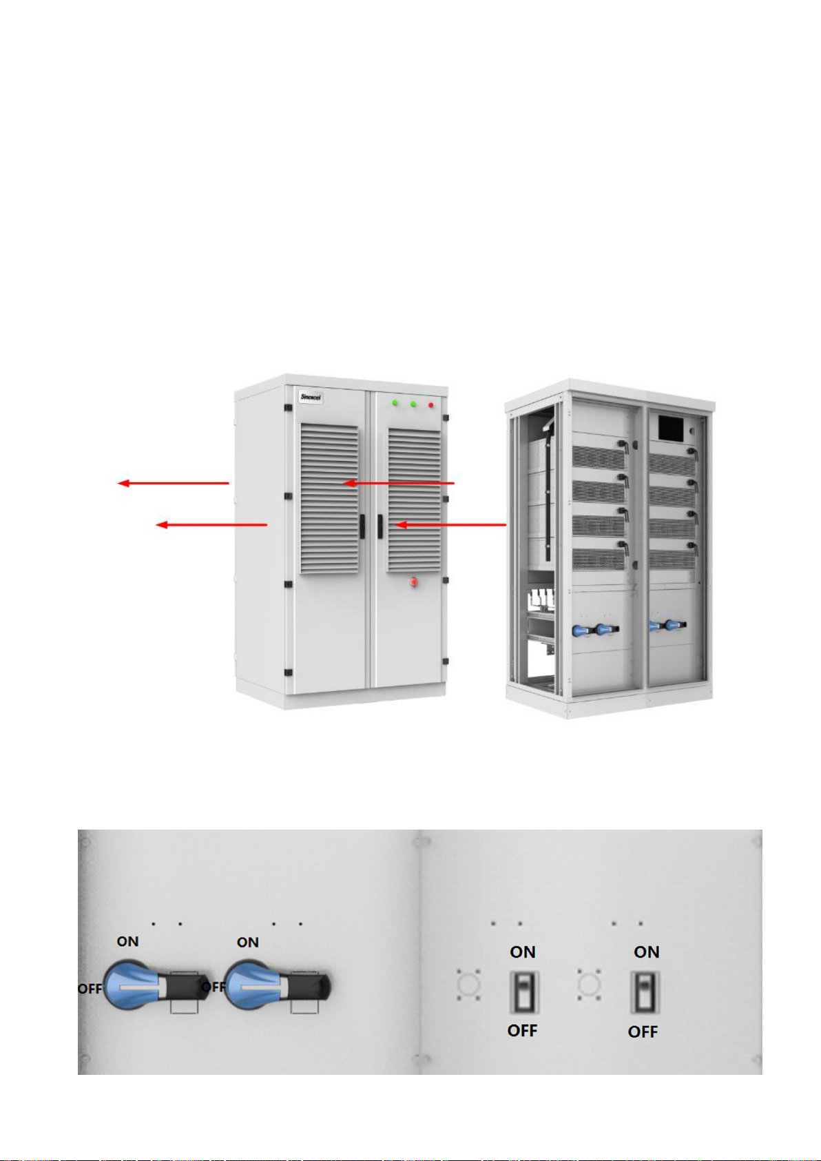
3.7 Switch status

14
Left - disconnector version Right picture - circuit breaker version
Location
name
illustrate
ON
ON
position
Isolation switch (rotate clockwise) - handle longitudinally Breaker (toggle up)
- handle up
OFF
OFF
position
Isolation switch (turn counterclockwise) - handle horizontally Circuit breaker
(toggle down) - handle down
4 Specifications
Technical Data Sheet
model
PDS1-750K-H
DC
rated power
750kW
Max power
825kW
DC side voltage range
500~1500V
Number of DC side
1/2/4
DC side max current
825/413/207A
BUS side voltage range
500~1500V
Number of BUS side
1
BUS side max current
825A
number of modules
8
System
Max conversion efficiency
98.6%
Dimensions (W×H×D)
1200×2100×970 mm
weight
845kg
noise
<85dB
Protection class
IP54
allowable ambient temperature
-40~55℃(Derating over 45℃)
cooling method
Forced air cooling
allowable relative humidity
0~95% (no condensation)
allowable altitude
3000m (Derating over 3000m)
Communication
Communication Interface
RS 485,Ethernet,CAN
Communication protocol
ModbusTCP/RTU
BMS access
support

15
5 Storing、lifting and transporting
5.1 Transport and storage
In order to ensure that the energy storage converter is in a better protective state during transportation, please
choose to transport with packaging as much as possible, and transport according to the indications of various signs on
the packaging. The illustrations of the packaging signs are shown in Table 5-1:
Table 5-1 Description of packaging label
Icon
Describe
Center of gravity mark, indicating the center of gravity of the energy storage
converter.
Lifting mark, indicating the position of the chain or rope when lifting the energy storage
converter.
The upward mark indicates the placement method when carrying and placing the energy
storage converter. It is strictly forbidden to put it upside down, horizontally or tilted.
Handle the logo with care, and avoid violent friction or collision during transportation and
placement.
During transportation and storage, the energy storage converter should be protected from
rain or moisture.
Since the center of gravity is not the mechanical center of the energy storage converter, please pay attention to the
center of gravity mark on the packaging box during transportation.
Regardless of whether the converter is packaged or not, it is strictly forbidden to tilt an angle greater than 5°during the
movement. Due to its large size and weight, an excessively large inclination angle may cause the equipment to fall
upside down, causing casualties or equipment damage.
Please avoid physical shocks to the equipment during the movement, such as suddenly lowering or lifting.
Please avoid transporting the energy storage converter under rain or bad weather conditions. If it is unavoidable, please
take necessary protective measures.

16
If the on-site installation is not carried out immediately after the completion of the delivery and acceptance work, the
energy storage converter with outer packaging should be stored in a ventilated, dry, and clean indoor environment. At the
same time, you should also pay attention to the following aspects:
⚫Restore the package to the state at the time of receipt, and the desiccant in the package must be retained.
⚫The storage floor is flat and sufficient to carry the weight of the energy storage converter with the outer packaging.
⚫When storing the equipment, you need to pay attention to ventilation and moisture prevention, and it is strictly
forbidden to store water in the storage environment.
⚫The storage environment temperature is required to be -40℃~+55℃, and the relative humidity of the storage
environment is required to be 0~95%, without condensation.
⚫Take care to deal with the harsh surrounding environment, such as sudden cold, sudden heat, collision, etc., to
avoid damage to the equipment.
⚫Regular inspections, at least once a week. Check if the packaging is intact to avoid insect bites. If the outer
packaging is damaged, it should be replaced immediately.
⚫If the storage time is more than half a year, the package should be opened for inspection, and the desiccant should
be replaced and repackaged.
The energy storage converter is a whole device, and it must not be disassembled during transportation or storage.
Equipment failures caused by modifications not authorized by Sinexcel are not covered by the warranty.
When the equipment is transported and stored, it is strictly forbidden to stack, and no other items are allowed to be
stacked on the top of the equipment.
When the equipment is transported and stored, it should be ensured that the environment in which it is located is free of
corrosive gas, no high-temperature heat source, not excessively dusty, and meets the fire protection requirements.
Storage without packaging is strictly prohibited.
5.2 Transfer
It is recommended to use a forklift to move the entire box body in a short distance without removing the shipping box.
When moving, pay attention to the center of gravity mark and lifting mark position on the box, and ensure that the
transportation tool has sufficient carrying capacity. Lifting is strictly prohibited.
Moving the energy storage converter without a packaging box is usually used near the installation location of the
equipment. It is recommended to use a forklift for operation. When using a forklift, the bottom baffle of the energy storage
converter needs to be removed first.
1) Forklift movement (preferred)
Using a forklift to transport the energy storage converter is a standard way of movement. The center of gravity of the
converter should fall between the two forks of the forklift and be pre-inserted to ensure that it will not tilt after being lifted. As
shown in Figure 1-1, the length of forklift forks shall not be less than 1.2m.

17
In the process of using a forklift to fork, lower and move the energy storage converter, it is necessary to ensure that it is
slow and stable, and the energy storage converter must be placed on a firm and level ground.
In the entire process of using a forklift to operate, it is necessary to strictly abide by the forklift safety operation specifications.
Due to the large volume of the energy storage converter, it may obstruct the driver's sight, so assistance should be provided
for cooperation.
≥1.2m
Fig 5-1 Schematic diagram of forklift
1) Pallet truck movement
The use of a pallet truck to move the energy storage converter is only suitable for conditions where the transportation
route is relatively stable. During transportation, the center of gravity of the converter should fall between the two forks of the
forklift and be pre-inserted to ensure that it will not tilt after being lifted. As shown in Figure 3-2, the length of the forklift forks
shall not be less than 1.2m, the inner distance between the two fork arms of the pallet truck shall not be less than 0.2m, the
outer distance shall not be greater than 0.8m, and the load-bearing capacity of the pallet truck must be ≥1500kg.
In the process of using a forklift to fork, lower and move the energy storage converter, it is necessary to ensure that it is
slow and stable, and the energy storage converter must be placed on a firm and level ground.
In the entire process of using a forklift to operate, the relevant safety operation regulations must be strictly observed. Due
to the large size of the energy storage converter, it may obstruct the operator's view, so assistance should be provided for
cooperation.
≥1.2m
≥0.2m
≤0.8m
Fig 5-2 Schematic diagram of pallet truck
Before moving with a forklift or pallet truck, the bottom baffle of the energy storage converter must be removed,
otherwise the bottom baffle will be damaged.

18
No matter which way you choose to move the energy storage inverter, you must ensure:
⚫Must always pay attention to the position of the center of gravity.
⚫Must be considered the volume and weight at all times.
⚫Must be ensured the safety of operators at all times.
Take necessary auxiliary measures to ensure that the equipment is transported to the installation site in good condition.
5.3 Out of the box inspection
5.3.1 Unpacking
After the DC converter is transported to the vicinity of the installation site, the transport box needs to be
removed. The removal steps are as follows:
①Remove the top panel of the box.
②Remove the wooden side panel of the packing box.
③Remove the shielding material from the packing box.
④Remove the anchor parts that fix the DC converter on the transport wooden bracket.
After removing the anchor parts between the DC converter and the transport wooden bracket, it is strictly
forbidden to transport the DC converter through the wooden bracket.
5.3.2 Test
Before leaving the factory, the DC converter has been checked by the staff of Shenghong Electric and packed
firmly. Nonetheless, the following items need to be checked after the DC converter shipping packaging has been
removed:
Check whether the quantity of each item on the packing list is consistent with the actual item;
Check whether the nameplate data of the product is consistent with the order contract, such as product model,
rated capacity, voltage level, etc.;
Check whether the factory documents and accessories are complete;
Check whether the appearance of the DC converter is consistent with the description in this manual;

19
Check the DC converter for deformation, peeling paint and loose parts.
The packing list of the PDS1-750K-H DC converter is shown in Table 5-2.
Table 5-2 Packing list
serial number
name
quantity
1
PDS1-750K-H-DC converter
(including cabinet door key and related accessories)
1 set
2
PDS1-750K-H User Manual
1 serving
3
Equipment wiring diagram
1 serving
4
Product certification
1 serving
5
Inspection Report
1 serving
6
Warranty Card
1 serving
Installation and debugging can only be carried out on the DC converter that has been inspected correctly and is
complete without damage. During the inspection process, if any problem is found, please contact the transporter
or Shenghong Electric in time.
Table of contents
Other Sinexcel Media Converter manuals


Popular Media Converter manuals by other brands

Roland
Roland VC-1-HS Brochure & specs

iConnectivity
iConnectivity iConnectMIDI quick start guide

Black Box
Black Box IC152A Specifications

Keyautomation
Keyautomation 900EGKD2 Instructions and warnings for installation and use

FibroLAN
FibroLAN S.CON1M User and installation guide

GRASS VALLEY
GRASS VALLEY 2020ADC instruction manual


