FibroLAN S.CON1M Manual
S.CON1M
Managed Single Channel
10/100BaseTX-FX Media Converter
User and Installation Guide
Version: 3.0
FibroLAN Ltd
Yokneam Star Building, P.O. Box 544, Yokneam-Illit, 20692 ISRAEL
Tel: 972-4-9591717 Fax: 972-49591718
e-mail: info@fibrolan.com web site: www.fibrolan.com

S.CON1M TX/FX Managed Converter
2
FEDERAL COMMUNICATIONS COMMISSION
AND
CANADIAN DEPARTMENT OF COMMUNICATIONS
RADIO FREQUENCY INTERFERENCE STATEMENTS
This equipment generates, uses, and can radiate radio frequency energy and if
not installed and used properly, that is, in strict accordance with the
manufacturer’s instructions, may cause interference to radio communication. It
has been tested and found to comply with the limits for a Class A computing
device in accordance with the specifications in Subpart B of Part 15 of FCC
rules, which are designed to provide reasonable protection against such
interference when the equipment is operated in a commercial environment.
Operation of this equipment in a residential area is likely to cause interference,
in which case the user at his own expense will be required to take whatever
measures may be necessary to correct the interference.
Changes or modifications not expressly approved by the party responsible for
compliance could void the user’s authority to operate the equipment.
This digital apparatus does not exceed the Class A limits for radio noise
emission from digital apparatus set out in the Radio Interference Regulation of
the Canadian Department of Communications.
Le présent appareil numérique n’émet pas de bruits radioélectriques dépassant les limites
applicables aux appareils numériques de la classe A prescrites dans le Règlement sur le
brouillage radioélectrique publié par le ministère des Communications du Canada.
CE Mark
The CE mark symbolizes compliance with the EMC directive of the
European Community. Such marking is indicative that the specified
equipment meets the required technical standards.
EUROPEAN UNION DECLARATION OF CONFORMITY
This equipment complies with the requirements of the European
EMC Directive 89 / 336 / EEC

S.CON1M TX/FX Managed Converter
3
Table of contents
Overview page 4
Planning your network with S.CON1M page 5
Content of the shipping container page 7
Product general description page 7
Front Panel page 10
Installation procedures page 11
Power connection page 12
Far End Fault (FEF) feature page 13
F/O cabling connection page 15
UTP cable connection page 15
DIP switches setting page 16
Fault Propagation (FP) page 17
Troubleshooting page 18
Specifications page 19
Jumpers’ usage for FP page 20
Installing, configuring, and managing S.CON1M page 21
Warranty Limitation page 31
Thank you for purchasing this S.CON1M
quality converter from FibroLAN. We hope that
this guide will help you to obtain the best
results from the device while minimizing
installation time.
If you still need help installing or troubleshooting the S.CON1M converter
after reading the detailed information in this guide, please visit our web
site, contact your reseller, or call FibroLAN directly.
Note: unless where indicated otherwise, in this guide S.CON1M applies also to
S.CON1M/T, S.CON1M/SMR7, S.CON1M/SMR, S.CON1M/SM,
S.CON1M/SML/L2/L3/LX, S.CON1M/SMF1, S.CON1M/SMRF13, and
S.CON1M/SMRF15.
TRADEMARKS
HP and OpenView are registered trademarks of Hewlett-Packard. Any other trademarks
mentioned in this manual are acknowledged to be the property of the trademark
owners.

S.CON1M TX/FX Managed Converter
4
1 – Overview
A media-converter may be defined as a device connecting two active network
components point-to-point over a media that is different from the ports of at least one
of these devices.
While Media Converters are considered part of the cable plant, in many cases they
must be remotely managed as any other network device. In particular this is true in
mission-critical, fully managed networks as well as in networks dispersed over large
areas to allow efficient control and maintenance. The S.CON1M is the only SNMP
managed single channel Media Converter available in the market.
While vendors offer such feature for large chassis based systems only, the need for
management is more intense in single channel devices, being deployed away from the
main wiring closets. Out-of-band management assures independence of the control
channel for enhanced system reliability.
SFS (Single-Fiber-Strand) versions of the S.CON1M make it a superb choice for
suitable installations saving 50% of the entire cable plant
An ideal media-converter should be a transparent element in the network, and its
ports may be considered as integral parts of the devices interconnected by it.
The IEE802.3u standard defines network span in terms of distances and bit times.
Conventional 100Base-TX/100Base-FX media-converters are based on repeater
technology, and they form a part of the collision domain created by the interconnected
devices. Therefore, the delay they introduce in the network severely affects the
allowed distances. Furthermore, if two class II repeaters (i.e., 2 hubs) are already
present in the same collision domain, then the use of a conventional converter is not
allowed as the repeater count may - in such case - exceed the limits. In all other
cases, meticulous PDV (Path Delay Value) must be performed prior to establishing the
possible distances for both the fiber optic (F/O) and copper segments.
The S.CON1M implements a non-repeater, full re-timing design. It creates a Buffered
Media Domain (BMD) over the F/O link, thereby eliminating all the above-mentioned
limitations.
The BMD created by two S.CON1M devices always operates at maximum
performance - 100Mbps/Full Duplex - while interconnected devices may operate at
different rates and modes. This provides full flexibility when planning a network.
The S.CON1M supports the Far End Fault (FEF) feature.
Far End Fault occurs when the signal detection is logically false from the receive
(incoming path) fiber port. When the S.CON1 detects a F/O Link Loss condition, the
unit will automatically send a Far End Fault signal to the remote device (on it outgoing
path). The remote device should support the same FEF feature and it will indicate a
Link Loss as well. (Refer to section 8 for more details).
The S.CON1M supports a bidirectional Fault Propagation mechanism (F>T and T>F).
When the S.CON1M senses a loss of F/O Link, it will automatically cut its TP port link.
If the S.CON1M is connected to a Master Unit, which does support Fault Propagation,
the latter will sense the loss of the F/O link and it will deliberately cut its TP port.
If the S.CON1M TP link fails, it will automatically cuts its F/O link. Thus the fault
propagates both from fiber to TP port and from TP to the fiber port.
The FP is enabled/disabled by means of the DIP switch S5.
The F>T and T>F selections are under control of the SNMP management module
(Refer to section 12 for a detailed description).
TFTP for software upgrade downloading and Telnet are also supported.
S.CON1M TX/FX Managed Converter
5
2 – Planning your network with S.CON1M
This section will guide you through network planning in order to obtain maximum
benefit - in terms of performance and functionality - from the S.CON1M converter and
other network devices. For specific instructions regarding the setup of each device,
consult section 10 - “DIP switches configuration”.
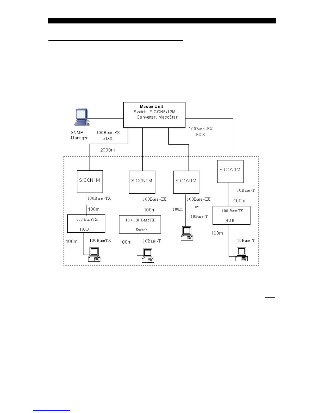
Possible network architectures are depicted in the following drawings
A. Typical basic configurations
Any networking device may connect to the copper port of the S.CON1M converters:
switches (of any type), hubs of any type (including 10Base-T!) or workstations (10 or
100Mbps).
While copper segments distances (between the device and the S.CON1M and
between such device and another device) reach their maximum at 100m/330ft, the F/O
segment (multi-mode fiber) may be extended to 2000m (6500ft) and much more over
single-mode fiber. (Up to 150Km). Single Fiber Strand (15-20 Km) can be deployed
saving 50 % of the cabling plant.
As an S.CON1M device is only slightly more expensive (if at all) than a plain 100Base-
FX transceiver (and certainly less expensive than an integrated 100Base-FX up-link
module in any of the interconnected devices), it is highly recommended to use any of
these configurations: extra benefits are obtained at little or no additional cost!
In certain configurations, additional benefits are obtained due to the implementation of
the BMD (Buffered Media Domain)
When the F/O link connects two hubs, S.CON1M not only converts media but also
splits the network into two segments, which reduces loads and collisions.

S.CON1M TX/FX Managed Converter
6
B. Typical Industrial Managed Network
The above network can be monitored and managed from any SNMP management
station running popular management platforms (e.g. FibroLAN MetroView, HP
OpenView, SNMPc, etc)
The software upgrade for each S.CON1M device can be performed via the
CLI management or Telnet (from the SNMP management station)

S.CON1M TX/FX Managed Converter
7
3 – Contents of the ship container
The contents of the S.CON1M, shipping container are as follows:
• One converter S.CON1M
• One AC power cord (excluding shipment to certain countries).
• . Powered cords for DC (-48V) models are NOT supplied.
• User and Installation Guide or Quick Guide
4 – Product general description
The S.CON1M family products are offered in several pre-configured models as
depicted in the table below.
Each of S.CON1M units can be also equipped with an internal DC Power Supply
(PS48, -36 – 72 VDC), instead of the standard AC P.S.
ETR: Extended Temperature Range (-10°÷+70°C) option is applicable to all S.CON1M
models. SCON1M products list
S.CON1M Single Channel 10/100Base-TX to 100Base-FX converter, BMD (Buffered
Media Domain), SC connectors, multi-mode - 2km,internal PS, SNMP
Managed
S.CON1M/T
Single Channel 10/100Base-TX to 100Base-FX converter, BMD (Buffered
Media Domain), ST connectors, multi-mode - 2km, internal PS, SNMP
Managed
S.CON1M/SMR7 Single Channel 10/100Base-TX to 100Base-FX converter, BMD (Buffered
Media Domain), SC connectors, single-mode - 7km, internal PS, SNMP
Managed
S.CON1M/SMR Single Channel 10/100Base-TX to 100Base-FX converter, BMD (Buffered
Media Domain), SC connectors, single-mode - 15km, internal PS, SNMP
Managed
S.CON1M/SM Single Channel 10/100Base-TX to 100Base-FX converter, BMD (Buffered
Media Domain), SC connectors, single-mode - 25km, internal PS, SNMP
Managed
S.CON1M/SM/L Single Channel 10/100Base-TX to 100Base-FX converter, BMD (Buffered
Media Domain), SC connectors, single-mode - 40km, internal PS, SNMP
Managed
S.CON1M/SM/L/2 Single Channel 10/100Base-TX to 100Base-FX converter, BMD (Buffered
Media Domain), SC connectors, single-mode - 70km, internal PS, SNMP
Managed
S.CON1M/SM/L/3 Single Channel 10/100Base-TX to 100Base-FX converter, BMD (Buffered
Media Domain), SC connectors, single-mode - 100km, 1550nm, internal
PS, SNMP Managed
S.CON1M/SM/L/X Single Channel 10/100Base-TX to 100Base-FX converter, BMD (Buffered
Media Domain), SC connectors, single-mode - 150km, 1550nm, internal
PS, SNMP Managed
S.CON1M/SMF1 Single Channel 10/100Base-TX to 100Base-FX converter, BMD (Buffered
Media Domain), single SC connector, single-mode - 20km, Single Fiber
Strand, 1310nm receive and transmit, internal PS, SNMP Managed
S.CON1M/SMRF13 Single Channel 10/100Base-TX to 100Base-FX converter, BMD (Buffered
Media Domain), single SC connector, single-mode - 15km, Single Fiber
Strand, 1310nm Tx/1550nm Rx internal PS, SNMP Managed
S.CON1M/SMRF15 Single Channel 10/100Base-TX to 100Base-FX converter, BMD (Buffered
Media Domain), single SC connector, single-mode - 15km, Single Fiber
Strand, 1550nm Rx /1310nm Rx internal PS, SNMP Managed

S.CON1M TX/FX Managed Converter
8
Key Features
• 10Base-T, 100Base-TX and 100Base-FX modes of operation
• Supports FEF feature (Far-End-Fault)
• Supports bi-directional Fault Propagation (F>T) (T>F).
• Comprehensive LED support :Indicators for Link, Activity (Tx, Rx), FDX,
100M, SD (signal detect) and power status
• Hardware based 10/100, Full/Half, Flow control and Auto-Negotiation
• Wire speed reception and transmission
• Supports 1K Mac addresses
• Automatic address learning and address aging (aging period is 300s)
• Frame length range: 64 ÷ 1536 bytes (VLAN tagged frames are thus
supported and can pass thru the converter)
• Desktop, shelf or wall mount installation
• ETR: Extended Temperature Range (-10°÷70°C) option for all S.CON1M
models
• Optional -48Vdc Power Supply for all S.CON1M models (PS48)
• RS232 Console port for Out-of band management on the front panel
• SNMP In-Band management
• The software for the S.CON1M (firmware) can be downloaded via the
TFTP routine
• Port based VLAN support
• Telnet support
General Description
All S.CON1M models have identical functionality and performance. Therefore, any
description or feature of one model refers to all other types.
The RJ-45 port operates in Auto-Negotiation mode: It may operate in 100Base-TX or
10Base-T and in both FDX and HDX modes, depending on the type of device to which
it is connected.
The TP port is a shielded RJ-45 port, cat.5, and 100m. The port can operate as an
MDI-II or MDI-X port depending on the MDI-II /MDI-X selector
The S.CON1M is equipped with an MDI-II/MDI-X selector on the front panel to allow
connection of either a switch/hub or a station, allowing the deployment of either a
straight or cross-twisted pair cable.
The F/O port supports 100Base-FX transmission in both FDX and HDX modes.
The conversion process creates a BMD, allowing unprecedented functionality and
performance. The F/O port is setup by default to operate at 100Mbps FDX

S.CON1M TX/FX Managed Converter
9
For optimized set-up, the S.CON1M l is equipped with an array of 7 positions DIP
switches accessible from the front panel.
The device provides extensive diagnostics and a status display with 7 high visibility
LEDs for the S.CON1M device.
Power Supply (including –48 models):
The system is equipped with a powerful power supply (100 - 240V universal input
or –48VDC), which in case of failure may be removed and replaced, without removing
the system from the rack. This minimizes Mean Time to Repair (MTTR) to 3 minutes.
A front panel LED indicates the power status.
Management:
The S.CON1M includes on its front panel in addition to the above-mentioned
indicators and controls a “management area”. This area includes all necessary
interfaces to set-up the SNMP agent of the device (RS232 Console port and two LEDs
RCV and Ready).
The software upgrade for each S.CON1M device can be performed via the
CLI management or Telnet (from the SNMP management station)
Refer to the Management section (section 16).
CAUTION
Radiation emitted from a fiber optic
connector may be hazardous to human
vision. Therefore, the following rules
must be strictly observed
All single-mode (SM) models are
CLASS I LASER PRODUCTS
And must be handled with special care
.
When not in use, keep the fiber optic
connector closed using its protective
cover.
Never stare directly into the fiber optic
connector of a powered device or into
the end of a fiber connected to it.

S.CON1M TX/FX Managed Converter
10
5 – Front Panel components Identification
1- MDI-II / MDI-X selector
2- 10/100Base-TX connector port (shielded RJ45)
3- Twisted pair operation (3 LEDs, 4 functions)
Link/ Act - twisted pair link present (LED steady lit)
When blinking implies activity (transmit or receive mode)
FDX - full duplex operation
100M - TP is working at 100Mbps (when the LED is off, the speed is 10Mbps)
4- SC fiber optic connector (left/Tx & right/Rx); ST connector (S.CON1M/T model) 5-
5- Fiber optic LED indicators
Link/ Act - twisted pair link present (LED constantly lit)
When blinking implies activity (transmit or receive mode)
SD (signal detect) signal present during receive mode
FDX - full duplex operation
6- MODE SETUP 7 positions DIP switches
7- POWER LED indicator
LED lit Main power supply installed and operating.
8- MiniDIN connector for management set-up and S/W updates (RS232 Console
port)
9- Management module status LED indicators
RCV – the internal SNMP agent is receiving data
Ready– When LED is blinking implies that the SNMP agent logic is in the
initialization stage. When LED steadies lit: SNMP agent is ready
S.CON1M TX/FX Managed Converter
11
6 – Installation procedures
S.CON1M all models (including –48 VDC models).
The S.CON1M products are suitable for desktop, shelf or wall mount installation
The device is intended for use with indoors power lines only
For Desktop use: Affix the supplied plastic “feet” (after peeling off the adhesive
protecting sheet) to the bottom of the devices, with each “foot” approximately 1 cm
from each edge. Place the device horizontally on a hard, clean surface (desk, shelf,
etc.), leaving free space around it for natural ventilation. Avoid placing the device on
other active, heat generating equipment and avoid placing such devices on other
S.CON1M unit.
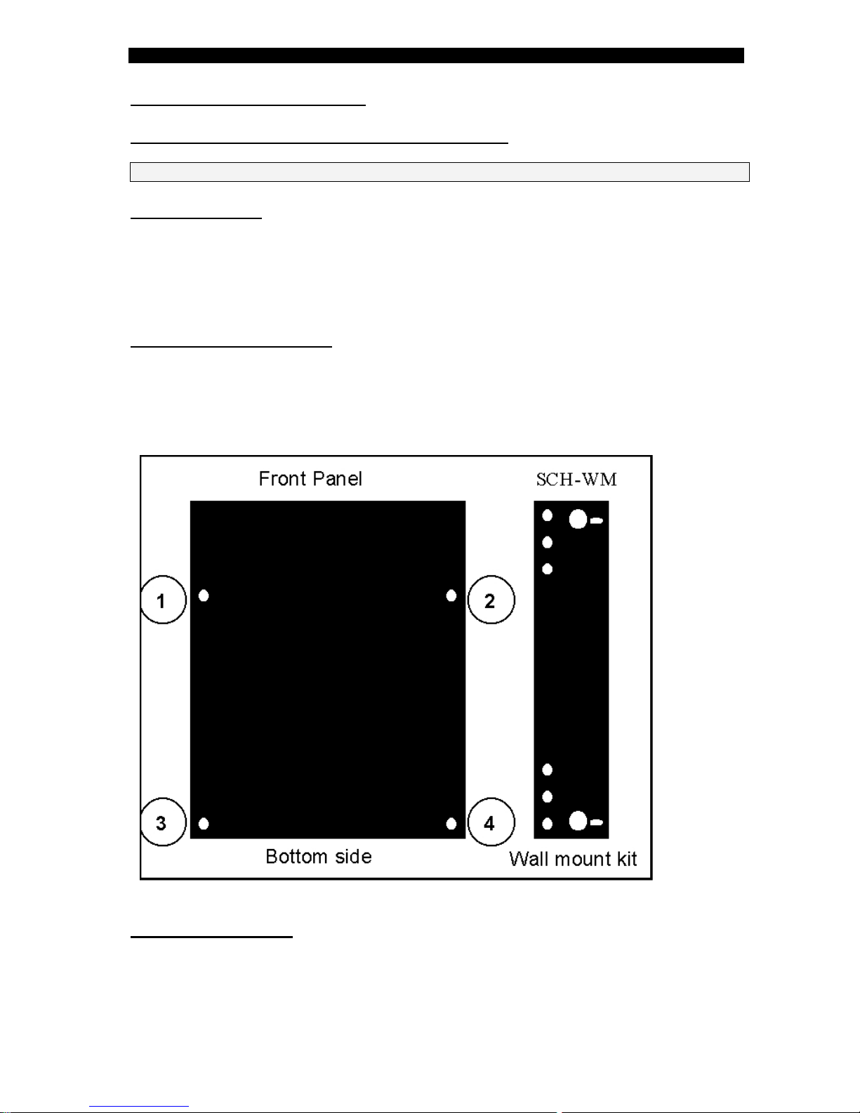
For wall mount installation
Attach the single channel wall mount kit (SCH – WM part # B161) with two (supplied)
screws to the base of the S.CON1M unit (select any 2 adjacent nuts: 1+2 or 3+4 or1+3
or 2+4) to achieve the desired mode of mounting. The screws to be fixed on the wall
should not protrude more than 8mm. Append the S.CON1M unit on the wall.
For Shelf installation:
Use the 19” Rack shelf (CTF-RM P/N B012) for installation of up to 3 S.CON1M
units. During the installation of several 19” Rack shelves, it is recommended to leave at
least 1cm ventilation space between two adjacent racks.

S.CON1M TX/FX Managed Converter
12
7 – Power Connection
CAUTION: When connecting a device to an AC (DC) power outlet,
always first connect the cord to the device, and ensure that it is
securely fastened. Only afterward connect the cord to the wall
outlet. Make sure to use grounded (3 way) outlets (in case of AC
models).
For each country FibroLAN (or FibroLAN’s distributor) provide with the product
an appropriate power supply cord which is safety approved in accordance with
related country’s National Electric Code
Connect to AC line socket at the rear of the converter, using the included power cord. The
S.CON1M will accept and automatically switch between any line voltage from 100 to 240 VAC,
50-60 Hz. There is no ON/OFF switch on the device. When the power is connected to the
device, the device is ON. The POWER LED on the front panel being illuminated will indicate
this
S.CON1M all AC models Rear Panel
S.CON1M with 48 VDC Power Supply ( PS48 -36 ÷- 72 VDC )
0-48VDC
V
S.CON1M TX/FX Managed Converter
13
Proceed as above using a suitable DC supply cable. Ensure that the polarity of the
cable complies with the polarity of the DC receptacle on the device as depicted above.
There is no ON/OFF switch on the device. When the power is connected to the
device, the unit is ON. The POWER LED being illuminated will indicate this.
NEVER OPEN THE DEVICE WHEN IT IS CONNECTED TO POWER LINES!
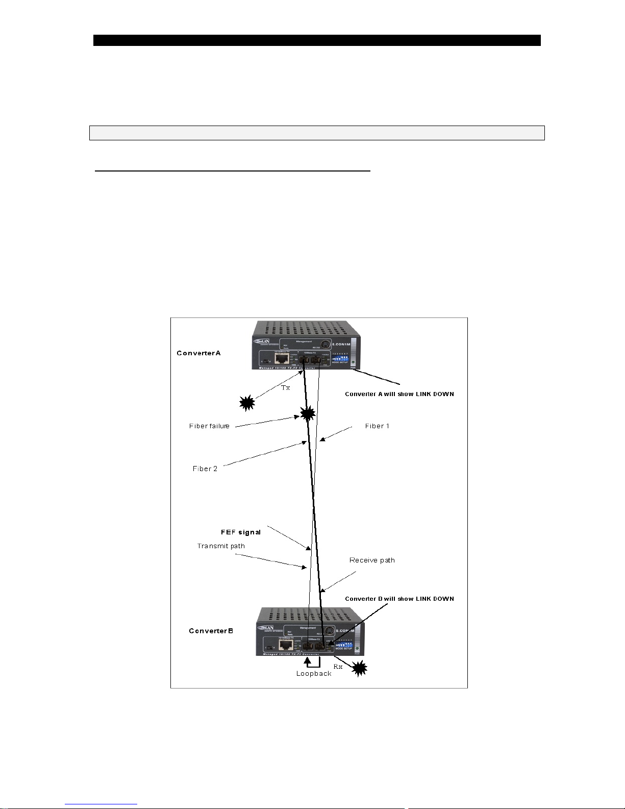
8 – 100Base-FX Far End Fault (FEF feature)
Usually a “LINK” indication is related to the incoming fiber only: F/O Link ON shows
that the path created by the remote transmitter, local receiver and the fiber connecting
them is operational. However if there is a fault in the other – outgoing - path (created
by the local transmitter, remote receiver and the fiber connecting them) – the indication
for such fault can be seen on the remote device only.
The FEF implemented in the S.CON1M closes this gap: if there is a fault in the
outgoing path and the remote device is FEF compliant (see below) then the F/O LINK
LED will go OFF on both the local and remote devices. In this way we avoid the
possibility of having a FX Link ON indication at one end while, in reality one of the data
Path is disrupted. The drawing shows the FEF functionality.
Any element failure on Receive path to Converter B, will cause the latter
to send FEF signal to converter A which will show F/O link down.

S.CON1M TX/FX Managed Converter
14
FEF feature with the SD ( Signal Detect ) LED
By means of the FEF feature along with the SD ( Signal Detect ) LED , we may
determine which fiber line connection is faulty within the F/O Link ( if one of the two
F/O lines is disrupted ). The SD LED lit in converter A implies that its F/O Tx line is
faulty. The combination of the FEF feature and the SD LED ( Signal Detect :
implies data signal present during Receive Mode ) provides a powerful and
efficient troubleshooting tool to easily identify the failing fiber connection within
a F/O link.

S.CON1M TX/FX Managed Converter
15
9 – Fiber Optic Connection
The S.CON1M is equipped with 1 pair of SC-type connector or single SC connector for
SFS (Single –Fiber – Strand) models
Do not remove the protective covers on the fiber connectors until you are ready to
connect the fiber optic cables. Power should be connected before attaching the fiber
optic cables. When dealing with fiber optic cables, it is essential to ensure that the Tx
at one end of the link is connected to the Rx at the other end of the link.
Some duplex fiber optic cables are color coded to help monitor the direction of data
transmission. If the fibers are not coded, special attention must be paid to ensure a
proper connection.
10 – Twisted Pair cable connection
The S.CON1M provides one shielded RJ-45 connector to interface to the twisted pair
link. The port operates in Auto –negotiation mode and according to the position of the
MDI-II / MDI-X selector switch located on the front panel
Use a shielded Cable Type 5 or higher grade, up to 100m (330ft) long.
STP cable carries a higher quality of signal and is less sensitive to environmental
noise. The 10/100BaseTX port (set to MDI-X) is normally designed to be connected
directly to a workstation, using a standard straight through patch cable.
In order to connect a Hub, or a switch, a crossover cable is normally used.
The tables below depict these functionalities.
Rules: 1. With the same type of TP ports (MDI-X < > MDI-X, or MDI > < MDI)
Use a crossover cable. With different ports (MDI-X < > MDI) use a straight cable
Set up the selector (MDI-II/MDX) located on the front panel according to the available TP
type cable and the setup of the remote connected TP port. Check if the remote TP port
does support Auto-Negotiation and act accordingly.
RJ F
R
T
45 PIN unction
x +1Rx -
6
2
3 x+
Tx -
RJ F
R
R
T
45 PIN unction
x +
1
x -
6
2
3
Tx +
x -
S
.CON1M PC (NIC)
Straight through cable connection between the S.CON1M
TP port and a workstation (MDI-X port < > MDI port)
RJ F
R
T
45 PIN unction
x +1Rx -
6
2
3 x+
Tx -
S.CON1M Hub / Switch
Crossover cable connection between the S.CON1M
TP port and a Hub or Switch (MDI-X > < MDI- X)
RJ FR
T
45 PIN unction
x +1Rx -
6
2
3 x+
Tx -
S.CON1M TX/FX Managed Converter
16
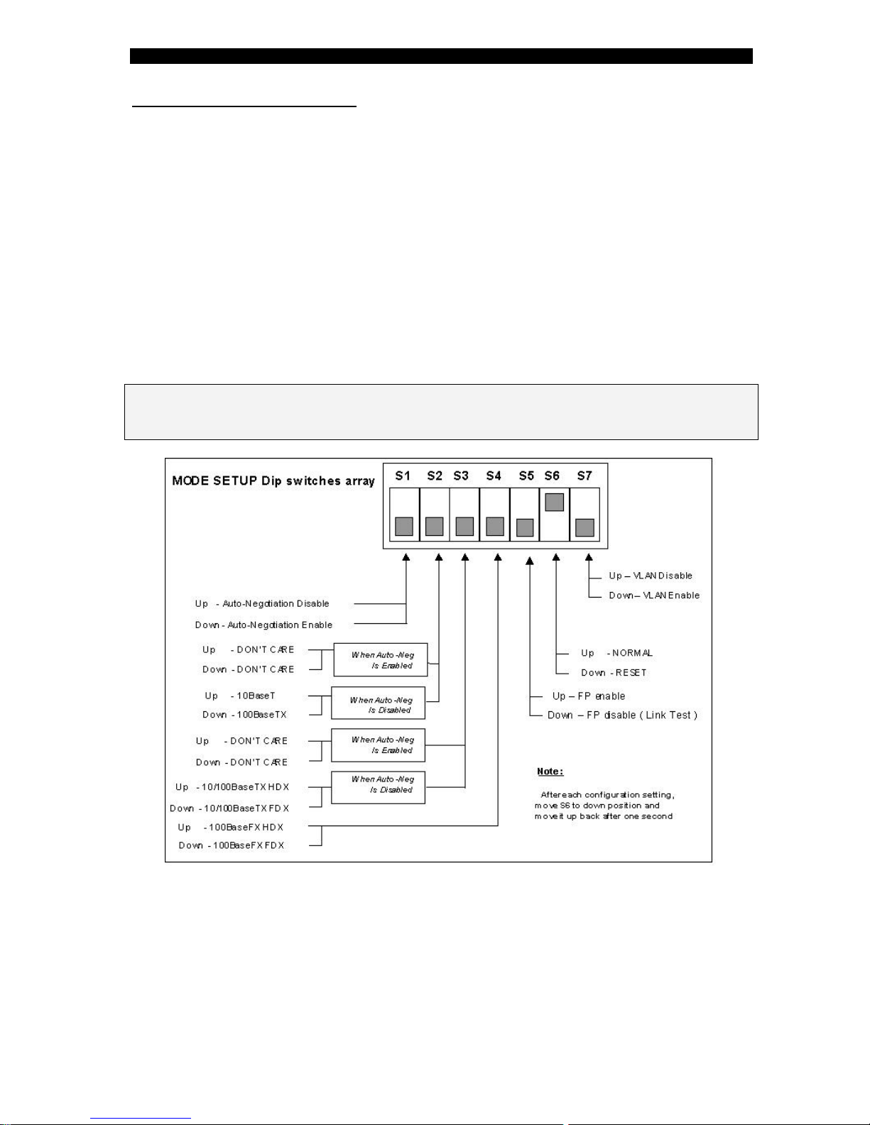
11 – DIP switches setting
Each S.CON1M unit is equipped with an array of DIP switches that facilitate the proper
setting of the TP and F/O ports for optimal operation.
Each port may have different settings.
A wrong setting will not necessarily result in a channel malfunction, but rather in non-
optimal operation (for instance - HDX operation instead of FDX).
The switches are recessed in the front panel to avoid incidental change of position.
Use a flat-head miniature screwdriver (or a similar tool), insert it through the slot, hold it
vertically to the panel against the switch to be set, and change its position up or down
according to the following table.
The below table shows that the S.CON1M is configured in Auto-Negotiation mode.
The VLAN mode (when enabled) implies that the internal management port
and the F/O port form one VLAN. In this way only remote SNMP management is
possible. (network SNMP manager connected to remote network)
For local SNMP management (SNMP Manager connected to local TP port)
switch the S7 to UP position.
Note: in S.CON1M units, the setting may be changed from the management station. In
such case the real status of each function is indicated by the appropriate LED and not
necessarily by the position of the DIP switches.
Normally the DIP switch S5 is in FP disable mode (Down) prior to the installation.
After having established the F/O and TP links and verified that the SNMP management
module is working properly; you may set the Fault Propagation to the required mode.
DIP switch S5 in UP position will enable both F>T and T>F.
By means of the management you may enable/ disable F>T and/or T>F.
The setting through the management will override the DIP switch S5 and vice versa.
To perform a Restore default parameters operation:
1. Ensure that the DIP switches are in their default setting positions
2. Perform the management command: “Restore device default” (see Figure-9
management section)

S.CON1M TX/FX Managed Converter
17
12 – Fault Propagation ( FP) mechanism
The main purpose of fault propagation mechanism implemented in media converters is
to allow real-time notification of any link failure to upper hierarchy devices (e.g.
switches/routers with redundant links), consequently activating an alternate path to
communicate with a mission critical site. However, such mechanisms implemented in
other vendors’ products, may suffer from an inherent drawback. These are typical bi-
directional mechanisms: fault propagates both from fiber to TP port and from TP to the
fiber port. When such devices are connected to modern devices implementing FEF
(Far End Fault) it may become a lethal combination: while propagating the fault as
intended, when fault (original link break) is repaired (i.e. original link is restored), such
systems will hang and can be restored only by manual intervention.
The powerful fault-propagation mechanism implemented in the S.CON1M prevents
such deadlock. The fault propagation is bi-directional, (F >T, and/or T >F). When
S.CON1M senses loss of its UTP link, it deliberately cuts its F/O link (T > F) and if the
F/O link is disrupted, the SCON1M will cut its UTP link (F > T).
The S.CON1M utilizes a unique bidirectional FP mechanism. When turned on, both FP
directions are at their “stand by” state, hence, F>T or T>F can be activated. However,
only one FP direction can be activated at any time. When a FP direction has been
activated due to a link down signal, the other direction FP is blocked and cannot be
active for as long as the first direction FP holds. This powerful mechanism allows free
operation of the S.CON1M with all types of FP or FEF enabled devices.
When a Master Unit at the central node (router/switch) becomes aware that its TP port
is disrupted (to which a remote end device is connected), it may trigger a back-up
mechanism (if equipped with such feature and a redundant link is needed to the
remote site) and/or alert the network manager.
The FP mechanism is enabled/disabled by means of the DIP switch S5, whereas the
F>T and T>F are under control of the SNMP agent management module.
The FP mechanism should be disabled while installing or maintaining the network.
Normally while installing a F/O network, it is common to establish first a F/O link and
only afterwards to connect the network devices to the converters.
The Link Test mode is for diagnostic purposes.
The Link Test in the S.CON1M unit is enabled through the DIP switch S5 (UP position)
disabling the FP mechanism.
In this mode each of the link segments (typically 3: TP, F/O, TP) provides separate
and true indication of its integrity therefore the defective link can be identified and
consequently repaired (following the FP activity due a link failure). After repairing (or
completing installation), set the DIP switch S5 to Down position to resume the Fault
Propagation mechanism.
While in TEST mode, the S.CON1M provides full functionality and run normal data
traffic, except the fault propagation is disabled. In other words, if one or both
converters forming the link are – by mistake or negligence left in this mode, it will not
obstruct the normal data traffic.
When interconnecting some legacy devices, you may experience linking-up problems.
In such case, it is recommended to disable momentarily the Fault Propagation feature
(remain in Test Mode). If however, the FP is needed, make sure that all the links (F/O
and UTP) are operative in the network, and only afterwards re-enable the FP
mechanism.

S.CON1M TX/FX Managed Converter
18
13 - Troubleshooting
Note: disable momentarily FP (S5 UP) when performing the following procedures
Problem & symptom Indication Corrective Action
No power Main power LED
not lit (PWR LED) Check that the power supply cable is firmly
connected to the main power supply and rack
mount power source.
Check that the AC input power source is between
100 and 240VAC.
Network problems No communication
on network On the “ mode setup “ dip switches, verify that the
S6 is in the up position (normal position)
Move S6 to the DOWN position and move it back
to the UP position after one second (Reset
operation)
Copper link not working at all Link LED not lit Verify if the remote connected TP does support
Auto-Negotiation mode and setup the dip switches
accordingly
Check that MDI-II/MDI-X is in position “ X “ for a
switch or a hub
Check that MDI-II/MDI-X is in position “II” for a
STATION or an up-link port.
Check that the connection cable is well connected
at both ends. Verify that the correct LEDs are lit
On the “mode setup “ Dip switches move S6 to
the DOWN position, and move it back to the UP
position after one second.
If the remote TP station does
not support Auto-Negotiation
mode
Unpredictable Change the “ mode setup “ dip switches according
to the remote TP port speed and Half/Full Duplex
mode (after having disabled Auto-Neg mode)
Move the S6 to the DOWN position and move it
back to the UP position after one second
Fiber link not working Link\Act LED not
lit
Check that the receive fiber is properly connected
to the transmit port of the remote fiber device
AND the transmit port to the receive port of the
remote device. Check the position of the “MODE
SETUP “ S4. Check that the fiber optic power is
the required receive power on the receive fiber
connector at the S.CON1M end.
Check if the SD LED is lit and according to figure
in page 14 , you may determine which fiber line is
faulty ( if this is the case )
Improper network traffic Runt and late
collision
On “mode setup switches”, move S6 to DOWN
position and move it back to the UP position back
after one second. (Reset operation)
Check ports configurations on the “mode setup “
Verify that both ends of F/O links are set to the
same mode (Half Duplex OR Full Duplex).
Check that both sides of UTP connection are in
same mode (10Mbps Half duplex OR 10Mbps full
duplex OR 100Mbps Half duplex OR 100Mbps full
duplex).
If the problem persists after carrying out the above procedure, do the following: replace the
suspected S.CON1M with another similar working unit, perform the requested setup. If that
has solved the problem, send your S.CON1M for repair. If the problem still persists, there is
probably some sort of general network failure. Call FibroLAN technical support
( support@fibrolan.com; Tel :972-4- 9591717; Fax : 972-4-9591718 )

S.CON1M TX/FX Managed Converter
19
14 - Specifications
Standard Compliance
IEE 802.3u, 100Base-TX-FX, IEEE 802.3: 10Base-T
Auto Negotiation on TP, IEEE 802.3u
Back pressure and IEEE 802.3x compliant Flow control
Supports 1K Mac addresses
Frame length range: 64 ÷ 1536 bytes
Conversion Method: BMD (Buffered Media Domain) with Fault Propagation
VLAN per port support
100BaseTX port
• RJ-45 connector (10/100Base-TX port)
• Auto Negotiation (default) or Manual mode (Auto-Negotiation disabled)
• 100m over UTP/STP 100ohm cat.5 cable
• Auto-polarity correction
• MDI-II/MDI-X selector on the front panel
Diagnostics
• 10/100Base-TX port: Link, Activity (Tx, Rx), Full Duplex, 100Mbps
• 100Base-FX F/O port LEDs: Link, Activity (Tx, Rx) SD), Full Duplex
• Power: power LED indicator
100Base-FX port
• 1310nm multi-mode, Duplex SC (Optional ST), 62.5/125 µ fiber, Distance: 2000m
(6500ft) Full/half duplex switch selection (Mode Setup S4 Dip switch)
Minimum output power: -18dBm
Input sensitivity: -32dBm
• Single Mode Fiber:S.CON1M /SMR7, SMR, SM, SM/L/L2/L3/LX (7,15,25,
40,70,100,150Km)
Minimum output power: -20, -16, -15, -11, -2, -5, 0 dBm respectively.
Input sensitivity: -30, -30, -33, -33, -35, -38, -38 dBm
• Single Strand-Fiber (SFS): S.CON1M / SMF1 (20Km), SMRF13, SMRF15
(15Km)
Minimum output power: -16 dBm
Input sensitivity: -30 dBm
Environmental /Physical
Power Supply
• S.CON1M with standard AC P.S.
• S.CON1M with DC P.S
100 ÷ 240 VAC, 50 ÷ 60 Hz. IEC connector
-36 ÷ - 72 VDC (PS48)
Power consumption S.CON1M all models: 6 watts
Operating temperature: 0° ÷45°C (32-113°F)
Storage temperature: -20°÷+ 80°C (-22°F ÷176°F)
Humidity: 10% ÷90% non-condensing
Safety: UL 60950, EN60950
Emissions: FCC part 15, Subpart B Class B, VCCI
Class B
ICES 003: 1997,Class B; EMC Directive
89/336EEC
Dimensions/weight:
120x170x40mm/0.5kg (excluding wall-
mount type) 4.7”x6.7”1.6”/1lb
Specifications are subject to change without prior notice
S.CON1M TX/FX Managed Converter
20
15. Jumpers usage for Fault Propagation
References:
Page 16 (DIP SWITCHES CONFIGURATION)
Page 17 (FAULT PROPAGATION MECHANISM)
Page 28 Management section (Figure 9 – terminal: device control menu)
Fault Propagation setup
Normally the DIP switch S5 is in FP disable mode (Down) prior to the installation.
After having established the F/O and TP links and verified that the SNMP management
module is working properly, you may set the Fault Propagation to the required mode
(F>T and/or T> F)
DIP switch S5 in UP position will enable both F>T and T>F.
By means of the management you may enable/ disable F>T and/or T>F.
The setting through the management will override the DIP switch S5 and vice versa.
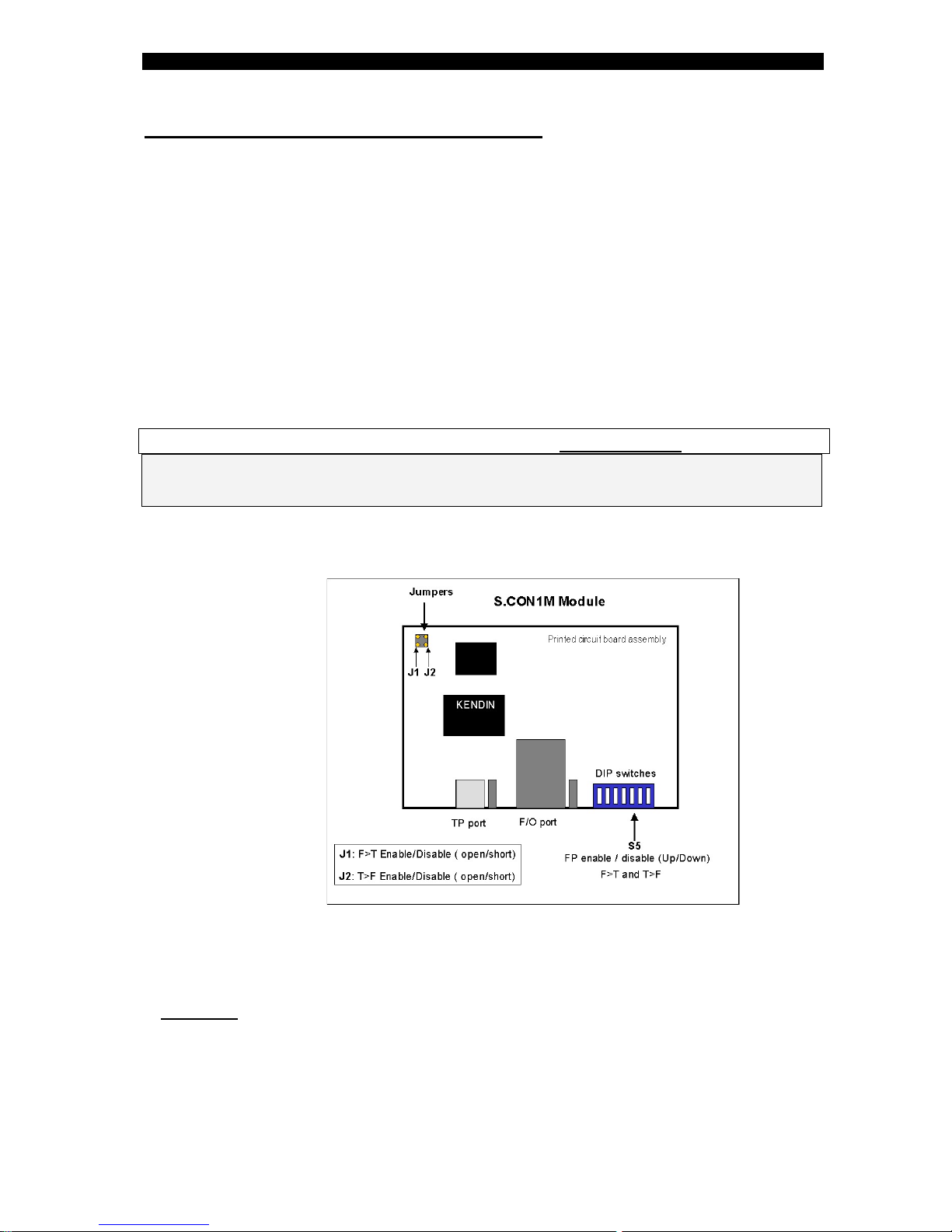
IF it is necessary to disable permanently
the FP modes of operation : F>T and / or T>F
You may use the jumpers J1 and J2
See the drawing below (by default the jumpers are open= FP enable)
Note: The jumpers setting should be carried out only by Technical Support staff. Disconnect
the power from the unit before setting the jumpers.
Warning: opening the product's case may annul warranty. If you wish to
change setting as described here, you must obtain permission in writing
from FibroLAN Customer Support Organization prior to doing so.
Permission will be specific to a service engineer and to units (identified
by serial numbers).
Table of contents
Other FibroLAN Media Converter manuals


