Sinexcel PDS1-45k User manual

PDS1-45k/ PDS1-60k
DC-DC Converter User Manual
Ver 1.00

User's Manual
Sinexcel PDS1 DC-Boost Converter
Data Version V1.0
Date of filing2023-02-07
Applicable toPDS1-45k, PDS1-60k
Shenzhen Sinexcel Electric Co., LTD provides a full range of technical support for customers, users can
contact the nearest office or customer service center of Shenzhen Sinexcel Electric Co., LTD
Shenzhen Sinexcel Electric Co., LTD.
All rights reserved. Contents are subject to change without notice.
Shenzhen Sinexcel Electric Co., LTD
Company website: www.sinexcel.com
Address:Block 6, Block 2, Nanshan Baiwangxin Hi-Tech Industrial Park, No.1002 Songbai Road, Nanshan
District, Shenzhen, China
Postcode:518055
Customer Service Hotline:0755-8651-1588
Company Fax:0755-8651-3100
E-mail: service@sinexcel.com

Catalog
Chapter 1 Overview .....................................................................................1
Model Definition ..............................................................................................................................................................1
Explanation of Symbols....................................................................................................................................................1
Manual Tip Identifiers .....................................................................................................................................1
Transformer Tip Identifiers..............................................................................................................................2
Safety instructions ............................................................................................................................................................2
Safety instructions in mechanical installation..................................................................................................3
Safety instructions in the electrical connection ...............................................................................................4
Safety instructions during operation of the equipment ....................................................................................4
Safety instructions for repair and replacement ................................................................................................5
Miscellaneous..................................................................................................................................................5
Caution .............................................................................................................................................................................6
Personnel requirements ...................................................................................................................................6
Scope of use of the equipment.........................................................................................................................6
Enclosure marking...........................................................................................................................................6
Instructions ......................................................................................................................................................6
Chapter 2 Introduction of optical storage system ........................................................7
System Application...........................................................................................................................................................7
System structure diagram ................................................................................................................................7
Dimension ........................................................................................................................................................................8
Appearance display diagram.............................................................................................................................................8
Technical Parameters........................................................................................................................................................9
Technical description......................................................................................................................................................11
Principle Description .....................................................................................................................................11
Function Description .....................................................................................................................................12
Derating.........................................................................................................................................................12
Chapter 3 Equipment transportation, storage and installation ...........................................14
Transportation and Storage.............................................................................................................................................14
Installation flow..............................................................................................................................................................15
Unpacking and inspection...............................................................................................................................................15
Converter identification and preparation ........................................................................................................................15
Installation requirements ................................................................................................................................................16
Environmental requirements..........................................................................................................................16

Carrier requirements......................................................................................................................................17
Electrical Connection .....................................................................................................................................................17
Recommended System Configuration ...........................................................................................................17
Terminal Introduction....................................................................................................................................18
System grounding..........................................................................................................................................19
DC output side wiring ...................................................................................................................................20
Photovoltaic input side wiring.......................................................................................................................21
Connecting the communication cable............................................................................................................23
Single module application system connection...............................................................................................26
Multi-module application system connection................................................................................................27
Post-installation inspection.............................................................................................................................................28
Equipment installation check.........................................................................................................................28
Electrical and communication check .............................................................................................................29
Chapter 4 Control and parameter setting process ........................................................30
Web connection ..............................................................................................................................................................30
Multi-module multi-monitoring application settings ......................................................................................................31
Step 1.............................................................................................................................................................31
Step 2.............................................................................................................................................................32
Step 3.............................................................................................................................................................33
Step 4.............................................................................................................................................................33
Step 5.............................................................................................................................................................34
Step 6.............................................................................................................................................................34
Single monitoring application setting .............................................................................................................................35
Step 1.............................................................................................................................................................35
Step 2.............................................................................................................................................................37
Step 3.............................................................................................................................................................38
Step 4.............................................................................................................................................................38
Step 5.............................................................................................................................................................39
Step 6.............................................................................................................................................................39
Step 7.............................................................................................................................................................40
Switching........................................................................................................................................................................40
Check before power on..................................................................................................................................40
Power-on steps ..............................................................................................................................................40
Steps to shut down the device........................................................................................................................41
Chapter 5 Maintenance and repair.......................................................................43
Working environment and operating condition inspection .............................................................................................43

Electrical and fixed partsconnection check.....................................................................................................................43
Cleaning and cleaning ....................................................................................................................................................43
Chapter 6 APPENDIX ...................................................................................45
Appendix I:Quality assurance and after-sales service ................................................................................................................45

~1~
Chapter 1 Overview
Model Definition
Model Definition.
PDS 1 -
DC converter with wideinput voltage range
SingleConversion
Power:45k --- 45kW
60k --- 60kW
SN Definition
SH0 YYMMDD
Module part number
YY:Year
MM:Month
DD:Date
Sinexcel code
Serial number
Figure 1-1 Model Number an SN Number Definition
Explanation of Symbols
This manual covers the installation and use of the Sinexcel Electric PDS1-45k/PDS1-60k DC-DC Boost
Converter.
To ensure the user's personal and property safety or efficient use of this product, please read this manual
carefully before installation and use.
Manual Tip Identifiers
The following is a list of identifiers used in this manual. Please read carefully and understand the
meaning of each identifier.

~2~
DANGER
This symbol indicates that there is a danger during operation and that failure to comply with
such warnings may directly result in serious injury or death.
WARNING
This symbol indicates that there are potential hazards during operation and failure to comply
with such warnings may result in personal injury or death.
CAUTION
This symbol indicates that there is a potential hazard during operation and that failure to
comply with such warnings may result in damage to the equipment.
"Instructions" are additional information in the manual that emphasize and supplement the
content, and may also provide tips or tricks to optimize the use of the product and help you solve
some of the problems in your application efficiently.
Transformer Tip Identifiers
The following is a list of identifiers used on DC-DC boost converters. Please read carefully and
understand what each identifier represents.
5min
This symbol indicates that after the converter is disconnected from the PV panel and the
energy storage converter, it is necessary to wait for 5 minutes before touching the internal
conductive devices.
This symbol indicates that the surface of the machine is hot during operation, so do not
touch the surface of the machine!
Please read the product manual carefully before performing any operation on the
converter.
Danger of electricity! Only professional and qualified personnel should install and
electrically operate this equipment.
Safety instructions
The PDS1-45K/PDS1-60K DC-DC boost converter is designed and tested in strict accordance with the
relevant international safety standards. The installation, commissioning, operation and maintenance
processes must comply with the safety practices for electrical and electronic equipment. Improper use or
~3~
misuse may endanger the personal safety of the operator or third parties, as well as damage the converter
or other property. To avoid this, the following safety precautions must be strictly observed during operation
and maintenance, which are described in detail in the respective sections.
WARNING
All installation, commissioning and maintenance operations must be performed by qualified
personnel. Professional technicians must meet the following conditions.
An engineer appointed by the manufacturer or its agent.
Have received professional training.
A complete reading of this manual and familiarity with safety matters in the operation
of electrical and electronic equipment.
Familiar with the relevant safety codes for electrical systems.
Professional technicians meeting the above requirements may perform the following tasks.
(1) Installation of the converter.
(2) Construction of PV-storage systems according to customer requirements.
(3) Commissioning of the PV-energy storage system.
(4) Operation, commissioning and maintenance of the PV-energy system.
CAUTION
Risk of injury if the equipment is operated incorrectly!
The instructions in the manual must always be followed when moving and placing the
converter.
Improper handling of the equipment may lead to electric shocks, burns, contusions,
etc.
Damage to the equipment caused by any private modification and dismantling of the
system (or equipment) operation without permission is not covered by the warranty.
Safety instructions in mechanical installation
DANGER
Always ensure that the converter is free of any electrical connections before installing the
converter.
CAUTION
Poor ventilation of the installation environment will affect the system performance!
Good ventilation needs to be ensured during the operation of the equipment. It is important
to keep the unit upright and the air ducts smooth, with no strong drafts blocking the air flow near
the air outlets, to ensure adequate cooling inside the unit.

~4~
Safety instructions in the electrical connection
DANGER
Do not touch the metal terminals of the PV panels without adequate protection.
CAUTION
The cables used in the photovoltaic-storage system must be firmly connected, well
insulated, and of proper gauge.
CAUTION
All electrical installations must meet national/regional electrical standards.
Permission must be obtained from the electricity authority of the country/region in which it is
located in order to operate on the grid.
Before connecting to the input power source, be sure to ground the system reliably and
comply with local electrical standards.
Safety instructions during operation of the equipment
DANGER
Any touching of the copper strip, contacts, terminals, etc. inside the equipment connected
to the photovoltaic panels and the energy storage converter circuit may cause a fatal burn or
electric shock!
Do not touch the terminals and conductors connected to the photovoltaic panels and
energy storage converter circuits.
Pay attention to any instructions and safety documentation regarding the connection
to the PV panel and the energy storage converter.
WARNING
There is a risk of electric shock inside the device! Do not open the converter housing while
the converter is in operation or under power.
A complete and closed cabinet enclosure protects the operator's personal property.
Any operation of this equipment needs to be performed or directed by qualified
personnel.
Please pay attention to the safety precautions listed in the user manual and other
documents.
Do not disconnect the input side when the output side of the converter is under load. If
disconnection is necessary, perform a shutdown operation first. Disconnect the input only after
disconnecting the output side disconnect switch of the converter and confirming that no voltage
is present.

~5~
CAUTION
It is strictly forbidden to block the air duct with foreign objects while the converter is in
operation.
Safety instructions for repair and replacement
DANGER
Improper maintenance operations on the equipment may lead to injury or equipment
damage. Before performing any operation, the user must strictly follow the following steps.
Disconnect all external connection switches and confirm with a multimeter that there
is no voltage at the converter ports.
Wait for at least 5 minutes until the internal energy storage components are
discharged, during which time it is strictly forbidden to touch the charged parts of the
equipment terminals, contacts, copper row, etc. with human body or any conductor.
Please carry out maintenance operations with an escort after complete power supply
to prevent any unexpected situation.
CAUTION
Do not allow unrelated personnel to enter the maintenance site!
Temporary warning signs must be posted or barriers erected to prevent unrelated persons
from entering the electrical connection or maintenance area when performing electrical
connection and maintenance work.
CAUTION
Restart the converter only after removing faults that affect the safety performance of the
converter.
the converter may only be re-powered after a complete power down of 1 minute.
The converter does not contain service parts inside, so if you need any repair service, please
contact our after-sales service.
CAUTION
Do not replace the internal components of the converter without permission. We will not be
responsible for any warranty or joint and several liability for any damage caused by this.
CAUTION
Contact or improper handling of printed circuit boards or other electrostatic sensitive
components can cause damage to the device.
Avoid unnecessary contact with the circuit board.
Observe electrostatic protection codes and wear anti-static bracelets.
Miscellaneous
WARNING
All safety markings, warning labels, and nameplates on the transducer.
must be clearly visible.

~6~
They must not be removed or covered.
Caution
Personnel requirements
The transducer must be commissioned and maintained by an engineer appointed by the manufacturer
or its agent. Failure to do so may endanger personal safety and cause equipment failure, and any resulting
damage to the equipment is not covered by the warranty.
Scope of use of the equipment
Converters are for commercial/industrial use only and may not be used as any energy saving equipment
associated with life support equipment.
Enclosure marking
The chassis marking contains important information for safe operation of the converter and must not be
torn or damaged.
Make sure the chassis marking is legible and replace it immediately if it becomes damaged or obscured.
Instructions
To make it easier for the user to read this manual, a large number of pictures are included. The pictures
are only for illustration purpose, please refer to the actual product for detailed display.
~7~
Chapter 2 Introduction of optical storage system
System Application
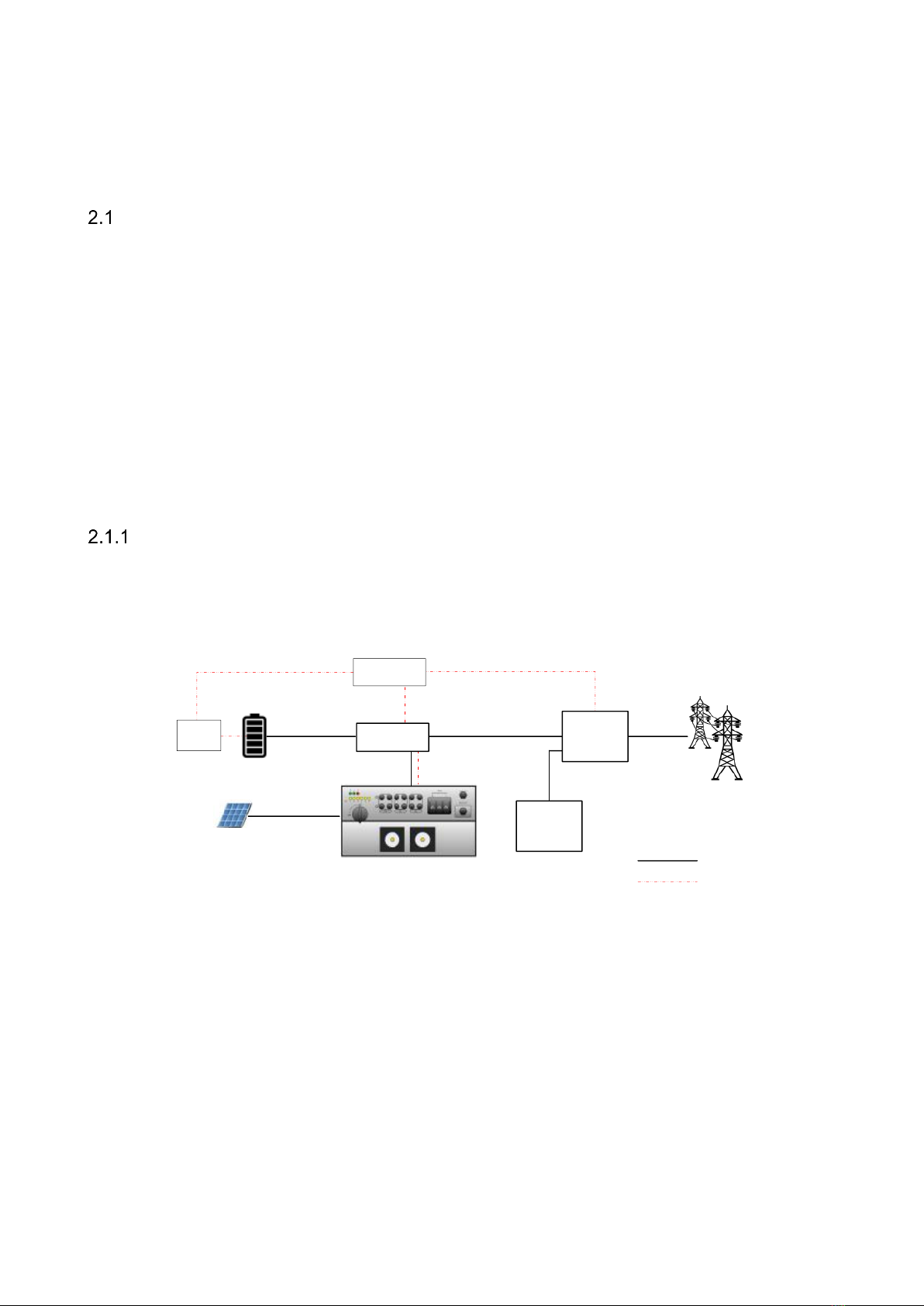
As shown in Figure 2-1, the photovoltaic storage system built by DC-DC booster converter includes
battery (group), energy storage converter, intelligent power distribution unit, EMS and BMS, and PV module.
The PV modules are connected to the DC-DC boost converter to realize the PV boost, and the MPPT control
is performed in real time according to the PV string energy state. After the boost, the DC bus of the storage
converter is connected through the bus side, and the discharge power of the storage converter is dispatched
through RS485 communication with EMS to realize the effective power transmission; the DC side of the
storage converter is connected to the battery pack, and the AC side is connected to the industrial load or
grid connection through the intelligent power distribution unit, and the energy management between the
three is performed through EMS to realize the energy dispatch of the photovoltaic storage system.
System structure diagram
The structure diagram of the optical storage system is as follows. The energy storage converter pushes
the data to the EMS, DC-DC boost converter or other upper computer system in real time.
RS485
【2】【6】【7】
【8】
Ethernet/RS485
EMS Ethernet/RS485
BMS
Intelligent
distribution
cabinet
Load
RS485
【1】
【3】
【5】
【4】
PCS
Legend
Power cable
Communication line
【9】
Figure 2-1 Energy storage system structure diagram
(1) PV module
(2) BMS battery
management system
(3)DC-DC booster
converter
(4) Battery pack
(5) EMS energy
management system
(9) Household and
industrial loads
(6) Energy storage
converters
(7) Intelligent power
distribution unit
(8) Grid
~8~
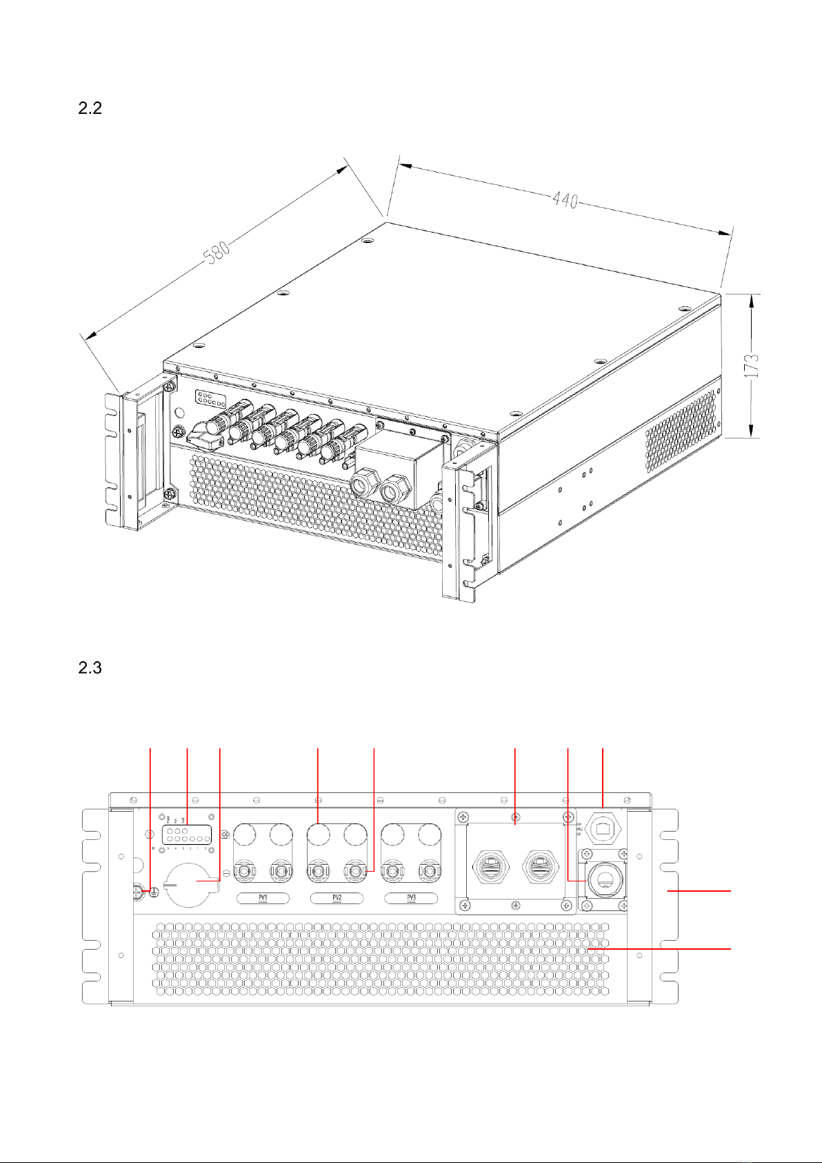
Dimension
Theoutline dimensions of PDS1-45K/PDS1-60K module models are shown in Figure 2-2.
Figure2-2PDS1-45K/PDS1-60K module external dimension diagram (unit: mm)
Appearance display diagram
The appearance of the PDS1-45K/PDS1-60K module panel is shown in Figure 2-3.
12 3 456 7 8
9
10
Figure2-3PDS1-45K/PDS1-60K module model panel appearance diagram

~9~
SN
Name
Description
1
Ground terminal
Grounding protection wire fixed point
2
Indicator light
To indicate the working status and ID of the module
3
PV input switch
To turn on/off the photovoltaic input
4
PV positive input port
MC4 terminal*6
To connect positive power cables to the photovoltaic
module
5
PV negative input port
MC4 terminal*6
To connect negative power cables to the photovoltaic
module
6
DC output port
To connect power cables to the PCS system
7
Signal interface
External communication interface
8
Reserve signal
interface
Not supported at present
9
Handle
Extraction and install module, not for load-bearing
10
Vent
Fan cover and air duct vents
Technical Parameters
The technical parameters of DC-DC boost converter are shown in the following table.
Table 2-1 Technical parameters table
Technical specifications
PDS1-45k
PDS1-60k
Photovoltaic side
Rated allowable power
45kW
60kW
Maximum inputvoltage1
1100V
1100V

~10~
Rated input voltage
600V
600V
Starting Voltage
250V
250V
MPPT voltagerange2
200~830V
200~1000V
Full Load MPPT Voltage
Range
430V~750V
575~900V
Number of MPPTs
3
3
Number of MPPT input
strings per circuit
2
2
Maximum input current
35A/35A/35A
35A/35A/35A
DC bus side
Rated allowable power
45kW
60kW
Operating voltage range
700V~830V
600~1000V
Rated Voltage
700V
700V
Rated Current
65A
86A
Maximum working
current
65A
86A
Efficiency
Peak efficiency
>99%
>99%
Basic parameters
Module size (width,
height and depth)
440*175*580mm
440*175*580mm
Net weight
22kg
22kg
Heat dissipation method
Air-cooled
Air-cooled
Working temperature /
humidity
-25-60
-25-60
Protection grade
IP66
IP66
Noise
≤70dB
≤70dB
Altitude
4000m (>3000m derating)
4000m(greater than
3000m reduction)
Working environment
pollution level
II
II
Protection
Photovoltaic reverse
connection protection
Yes
Yes

~11~
Insulation impedance
detection
Yes
Yes
Photovoltaic side switch
Yes
Yes
Temperature protection
Yes
Yes
Nighttime PIDrepair3
Yes3
Yes3
Photovoltaic input surge
protection
DC level 2 lightning protection
DC Class 2 lightning
protection
Fan/contactor failure
Yes
Yes
Leakage current
protection
Yes
Yes
Terminal Type
DC Busbar Terminal
Type
OT Terminals
OT Terminals
Photovoltaic terminal
type
MC4 terminal
MC4 terminal
Display/Communication
Display
LED
Communication
RS485/CAN(reserve)/RS232(reserve)
Certification
Safety certification
IEC62109,UL1741
EMC
EN61000 series
Notes.
1、The maximum input voltage is the maximum voltage that the PV input side of the converter
can withstand. Input voltage exceeding this voltage may damage the converter.
2、If the input voltage is not in the working voltage range, the inverter will not work properly.
3、This function is related to the power distribution system, the default is not enabled; customers
can set the enable or disable, and the compensation direction according to their needs.
Technical description
Principle Description
The DC-DC boost converter will decide whether to connect to the energy storage system according to
the strength of the PV module, when the PV module energy is weak, the DC-DC boost converter will
disconnect from the energy storage system due to the PV input undervoltage, and other components of the
energy storage system will realize energy deployment; when the PV module energy is strong, it will reach

~12~
the starting voltage of the DC-DC boost converter, and the PV open circuit voltage is within the MPPT
operation range. At this time, the DC-DC booster converter is normally connected to the energy storage
system, and the DC-DC booster converter can start working to raise the DC bus voltage to the normal
operating range of the energy storage converter, and MPPT control is performed according to the energy
strength of the PV module at this time. It can realize the conversion from wide input range to low output
range.
Function Description
Thefunctions of the PDS1-45K/PDS1-60K can be basically summarized as follows.
PV power boost control: The DC-DCboost converter can beconnected to the bus side of the DC of the
energy storage converter to realize PV access through MPPT boost, which can transmit PV power to the
battery for charging and also send PV power to the grid.
Data storage: DC-DC boost converter stores operation information, operation records, fault records and
other information.
Communication function.
⚫The standard RS485 interface can be connected to the energy storage converter for remote
control, remote upgrade and other functions.
⚫Standard RS485, CAN interface, etc. can be used to connect with other devices (reserved,
function not yet open).
Protection functions.
⚫Overcurrent protection
⚫Overload protection
⚫PV short-circuit protection
⚫PV reverse connection protection
⚫Bus bar reverse connection protection
⚫Environmental over-temperature protection
⚫Power module over-temperature protection
⚫Earth leakage current monitoring
⚫Insulation impedance detection and protection
⚫Photovoltaic voltage monitoring
⚫Busbar voltage monitoring
⚫Fan fault protection
⚫Communication timeout protection
⚫Bus bar electric switch fault protection
Derating
Derating of the converter is done to avoid overloading of the converter or to suppress potential faults.
~13~
The converter may be derated under the following operating conditions.
⚫Excessive internal temperature (both ambient and module temperature)
⚫Low photovoltaic voltage
⚫Remote power scheduling
Over-temperature derating
High ambient temperature and poor air duct will cause the converter to derate. Over-temperature
derating regulation is as follows.
⚫When the power device temperature reaches the upper limit, the converter will actively reduce the
input and output power until the power device temperature returns to the normal range, and then
the converter will gradually increase to the set value.
⚫When the ambient temperature inside the machine exceeds the upper limit, the converter will
automatically stop and power off to protect the safety of the machine itself.
The lower limit of over-temperature derating is about 70% of the rated power. If the derating reaches
the lower limit and still does not improve the temperature, the converter will automatically shut down.
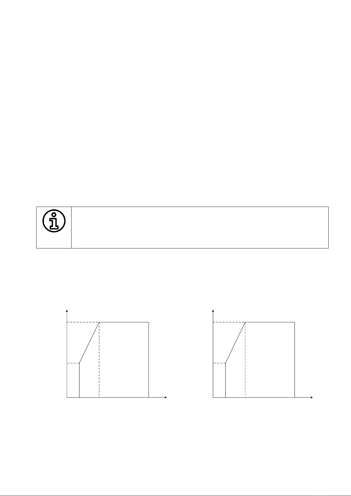
PV under-voltage derating
If the PV voltage does not reach the lower limit point of the full-load MPPT operation range, the DC-
DC boost converter cannot output the rated power at this time, and the PV output current is limited to
the specified range by derating.
200V 750V
45kW
21kW Work zone
430V
200V 900V
60kW
21kW Work zone
571V
Figure 2-4 PDS1-45K/PDS1-60K PV undervoltage derating diagram

~14~
Chapter 3 Equipment transportation, storage and installation
Transportation and Storage
When transporting and storing the converter cabinet, please pay attention to the marking on the packing
box. The following requirements should be met during transportation and storage.
⚫Do not remove the outer packaging of the DC-DC boost converter.
⚫No corrosive gases in the surrounding area.
⚫Storage temperature maintained at -40 ℃~65 ℃ and relative humidity maintained at
0%RH~95%RH.
⚫Non-dusty environment.
⚫Up to 5layersof stacking.
⚫Regular inspection is required during storage. If insects and rodents are found, the packaging
material should be replaced in time.
⚫Comply with fire protection requirements.
⚫After long-term storage, the converter needs to be inspected and tested by professionals before it
can be put into use.
~15~
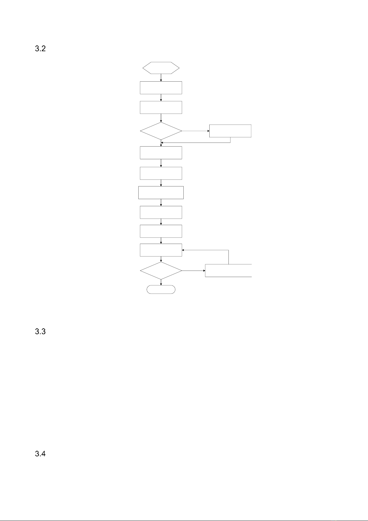
Installation flow
Start
Unpacking
inspection
Read manual
Install? Store
Choose Place
Move
converter
Regular
Electrical
connection
Pre-operation
inspection
Pilot run
TroubleshootingRun?
Over
No
Yes
No
Yes
Figure 3-1 Equipment installation logic flow chart
Unpacking and inspection
Each cabinet needs to undergo strict factory inspection and testing before shipment, and in order to
prevent damage during transportation, it is necessary to carry out unpacking inspection before the energy
storage device is ready for installation.
⚫Check whether the quantity of each item in the packing list is consistent with the physical object.
⚫Check whether the product nameplate data and the ordering contract are consistent, such as the
product model, rated capacity, voltage level, etc..
⚫Checking whether the factory documents and accessories are complete.
⚫Whether the DC converter is deformed and paint is lost.
Converter identification and preparation
Before installing the converter, please identify the converter type and the corresponding parameters.
This manual suits for next models
1
Table of contents
Other Sinexcel Media Converter manuals


Popular Media Converter manuals by other brands


J-Tech Digital
J-Tech Digital JTECH-4KSP4 user manual

Monacor
Monacor DADC-144DT instruction manual

Network Technologies Incorporated
Network Technologies Incorporated PWR-48V-5V1A installation guide

Sima
Sima SCW-2 user manual

Extron electronics
Extron electronics NAV E 121 Setup guide

Kramer
Kramer VP-435 user manual