Singer Empire NF-105 User manual

?4':
I
'-='-=#P:: .,JF'
INSTR
UCTION
MANUAL
g)
ii
T
I
1*
xtr[Hnx
NOISE AND FIELD
INTENSITY METER
: MoDEL NF-ios
--.s,
7r"-;r;t-rlrZr;o/"r/&c**t?4h4',?z'?hrtznzazulz'zza/
THE SINGER COMPANY ' METRICS DIVISION
=:.

\MARRANTY
THE
SINGERCOMPANY,METRICSDlVlSlON,warrants
eachnew instrument
to be freefrom
defects
inmaterial
and
workmanship,
effectiveafterdeliverytothe
original
purchaser
asfollows:
Commander-Instruments:Potentiometers,
Bridges,
VoltRatioBoxesandStandardResistors ....5 years
Sensitlve
Research*
ElectricalIndicating
Instruments .,.,.2 years
OtherElectricaland ElectronicMeasurinoInstruments .
.
.1 vear
Repair
or replacement
(at
ouroption)
without
charge
(F.O.B.
factory)
will
be
effectedwhenour
examinationsatisfactorilyindicatesthatdefects
aredue to workmanshipor materials.Electron
tubes,semiconductors,batteries,
fuzes,
lamps,thermoelements,
andRatioTran*
potentiometers
areexcludedfromwarrantycoverage.Warrantyreturnsmustfirst
be authorizedby thefactory,
lf theinstrument
or any
portion
thereof,
has
beenabused,misused,
damaged
by accident
or
negligence,
orif
anyserial
number
orseal
has
beenremovedoraltered,thewarranty
is
void.
Thiswarrantyisin lieu
ofallother
obligations
or liabilities
expressedor implied
andTheSinger
Company
neitherassumes,
nor authorizesany
person
to assumefor them,anyotherliability
inconnectionwithsalesofinstrumentsmanufactured
byTheSingerCompany,
Metrics
Division.
THESINGER
COMPANY.
METRICSDIVISION
915PEMBROKESTREET,
ERlDcEP0RT,C0NNECTICUT
r 3211
S.
LA
CIENEGA
BIVD.,LOS
ANGELES,
CALIFORNIA
REPAIR AND MAINTENANCE
Instrumentsshould
be returnedonlyon prior
written
authorization
fromtheSinger
Representa-
tiveor thefactory{t).Warranty
repairwillbe
made
uponwritten
request.Please
provide
thefol-
lowing
informationinorder
to expediteour processing
ofyour
instrument:
1. ModelorType 5. Approximate
date
instrumentwas
placed
in
operation
2. Serial
Number 6. Approximatenumberof
hoursof
use
3. Descriptionoftrouble{2) 7. Has
maintenanceactionbeen
previously
requested?
4. Testinstrumentsused 8. Othercomments
Upon
receiptofthis
informationourService
Departmentwill
send
you
service
dataor shipping
instructions.Upon
receiptof shipping
instructionsforwardtheinstrumenttothe
factory
prepaid.
lf requested,
an
estimate
of charges
willbe made
beforeworkbegins.
(1)
Contaci
MctricsDivision,BridSeport,
Connecticut
tgr Commandet', Empire', Panoramic',and Sensilive
Research' instruments.
Conlact
Metrics0ivision,los Angeles,
Calilornra
for Gerlsch'instruments.
(2)
Include
data
on symptoms,
measurementstaken,suspected
location
oI trouble,maintenanceaction
taken,andanyother
relevant
data.

A DDENDUM
for
MODEL NF-105 and NF-105 ( M-126 )
TYPE T1, TZ, and T3 TUNING UNITS
I. PURPOSE.
il.
To update schernatic diagrarns of T1, TZ, and T3 tuning units
to include the PRE IF OUTPUT circuitrv.
ADDENDUM.
A. Add the following circuitry to the T1 tuning unit schernatic:
R?45
75
P79ANDT7
Add the following circuitry
B. to the
OF
J206
TZ tuning unit schernatic:
TO JUNCTION
J2O3
AND
C9
R27
2
75
R274
t20
Jt3
TO JUNCTION

C. Add the following circuitry to the T3 tuning unit schernatic:
TOJUNCTION
OF
S6O2
(WIPER)
B
L6I9 (CENTER
TAP)
III. DESCRIPTION"
The PRE IF OUTPUT circuitry provides an i-f signal whose
bandwidth is greater than the i-f signal obtained frorn the
tuning unit i-f arnplifier. The output of the PRE IF OUTPUT
circuitry is used for spectrurn signature analysis.
Addendurn No. E 10

MODELS TA/NF-IO5
TA/NF-205, TA/
NF-Io5X-M-126
TA/NF.IO5-F ANd
TA/NF-105.FX
L PURPOSE.
To irnprove scan specifications frorn t0 db to 4 db.
It DESCRIPTION.
On Parts Lists and Schernatic Diagrarns, change capacitor C717
frorn 200 uuf to 100 uuf
Addendum No. EIZ

/"DDENDUM
for
MODEL T3l NF'-10
5
The following components are to be deleted from List of Replaceable Parts
for.
Modet T3/NF-105"
tici33"R,654
'The.ralues of components noted below appear incorrectly in the List of
Replaceable Farts for the Model T3/NI'-I05. Make changes as indicated.
Reference Symbol Descrip: ion Fart of
P.6Z4
R630
220 ohrns, l0%o,
l/ZW carbon 42 MC L f'. AmPlifier,T3
220 ohms, IA7o, llZW carboo 42 MC Ll'. Amplifier,T3
Change the schematic as follows:
io Deiete R633; connect C657 directly to the plate of V607'
',:" Delete R654; connect C56l directly to tbe control grid of V609.
Addendum No. E14

PART ONE
- II'lI]?ODUCTI0N
S:CiI0l; I - tesc:iption of lloise ar'd Field Intensity
Ileter lvlod.elNF-105
1. General. .
O A--l i ^^+i ^-
L. nIJPrrs4vIVIl . .
1. Technical Characteristics.
/
/ Tict ^f n^h-^-^-+^
r. !f) U UMill^UUIlglt U-
5. lescriptron of Major Conponents.
S:CTI0NII - Installation and Assernbly
6. Selection of Site.
n Assemhlv end Interccnnections. .
l. JID-slrurJ ollq 4
PARTTVTO
- OPERATI]{G
INSTRUCTIONS
SLC;IOf III - Operatlon
A
c
9.1
10.
10.1.
ra.2.
ta 7
'la /l
t-i.
12.
12.1.
12
,2,
PAil.'i
T}IP.EE
- REPAIN INSTRUCTIONS
SECTIO.IIV - ?heory of Operation
1A
L+.
ro.
., .7
-l A
'to
24.
2I.
22.
TABL' OF CON?EN?S
Page l{o.
1
I
1
4
B
Appii cati on and.Methocis of lvieasurement
. . 17
Control SettinEs. . ,6
Initial Adjustment. . 2I
'lni co i.-oqcrrrono-la ti
-...JltUD. . LI
Vi-sual-
Substitution (meter) ..2I
AuraL Substitution (slideback). , . , 24
I'ioise }ieasurernents
- lirect Reading . 25
licise l,-easurenents
- Broad.Band Antenna ,25
llo:seField Intensitv . .27
lvro ?eriainal R.
F. Vol-tmeter - Carrier
9
9
I,leasurement
s
Calibrarior: Procedure for T--/NF-105
(zc-zoo
;,:c)ancr-2/NF-10,
(2ac-4oc
:,:c)
Calibration Procedure for T-1/iIT-I05.
Carrier lield Intensity . .
ta
.29
Zq
- - /..-
-^-
'I'Un)-ng unII l'--Llrr.r-iU). . )U
Tunino Unit T-27')'F-*C!. . . .11
itrrni nr llni f .n_z/liF_1Ci.
- ,/.;F-rc,-. 42
)letec'-ors, I'.eterir:g
an3
Output Circuits. 45
TmnuIsr: Cpner:tor . .
--.^-r*-or 46
Sine,iave Oscillator. 49
Q+^- Lrtanrr-t^nc q2
JLel) l!LuelLUaLOI'S.
Poirer Su;piy. . )2
Alignnent Harness . 54

1ABLU OF CONTNI'ITS
Page No.
SECTI
O}i
SECTI ON
SECT
I ON
V - Alignment Procedure
2t. tuning Unit T-1/NF-105. . . . .
2t.I. I.F. Amplifier, 10.7 it{C
. . . . . . .
2r.2. R.F. Tuner,
20-55
I\IC.. . . . . . . .
21
,1
. R.F. Tuner, 55-zo0 t',l0 . . . . . .
24. Tuning Unit T-2/NI'-105. . . . .
24,I. I.F. Ar:rplifier, ,0 l.{C. . . .
24.2. Il.F. Tuner,200-400MC. . . .
25. Tuning Unit T-1/I{F-I]5. . . .
25,I. I.F. Amplifier, 42 \[C . .
25.2. R.F. luner,400-700 IrtC. . . .
25.r, R.F. Tuner, 700-1000
IIC. . . . . . .
25. hnpulse
Generator....
.
.......
27, Repetition Rate Generator. . . . . . . .
28. Sine Y/ave
0scil-Iator. . . . . . . . .
29. Carrier Zero Adjustment . . . . . . . . .
,0, Voltage Regulator . . . . . . . . . .
3L, FilamentVoltage.... ..
VI - Repai-rfnstructions
12. Ggnera]-
. . . . . . . . . . . . . . .
tt, ftnpulse
Generator . .-.
14.'StepAttenuator.
. . . . . . . .
15. Cear Trains . . . . .
,6, Relays.
... . . . . . . . .
J7, Pencil Tubes.. , . . . . . . . . . .
VII - Parts List. . . . . . . . . . . . . .
qq
qq
OU
oz
oz
o1
64
o/
o/
nv
ta

IRON?ISPIECE
Figure 1
Figure 24
kf otl?a /6
k'r -1170 t
tr'igure {
Ti orrno q
Figure 6A
a^
a r6ua s v!
Figure /ArB
Figure B
at mtTo I
Figure 10
Figure 11
Figure L2
Figure 1J
Figure 1{
tr1iorr^o I q
1a
.f].
gure l.o
Iigure lJ
Fi.gure 18
i'l dtr70 lv
tsr ftt?o /t)
Fi gure 21
tr'igure 22
Figure 2J
tr'i mrro tA
^ 4bsr v c.+
trtirrrrre 25
^a
-t,
1gure lo
Figure 2J
Trimrro 2R
Figure 2!
rr6urv //v
Figure JI
LIST OF ILLUSTRATIONS
!.gg*.
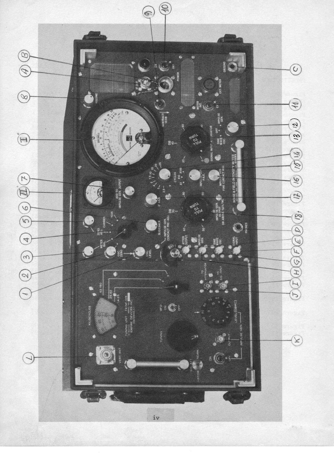
Main Unit, !'ront View
Typical Application of NF-105. . . . 2
List of Equi-pment
and Accessories. . . . 5
Allangernent of Parts in Accessory Transit Chest. . 6
Arrangenent of Parts in Optical Equipment Transit Chest. 7
Interconnection BetvreenVarious Cornponents
. . . . . . . 10
Sroad Band Antenna 20 to 1000 IvlC . . IJ
Application andlvlethods
of lleasurement. . V
Sof -rrn fnr Dro'l i n'i ror:r itrl-i.c+'
r - v*rrurrrarJ ^qJ uo ur;l8[tS 15
Conversion Charts. . . . . o . . . . . . . . I9r2O
Correction Factor for Cable Losses . . . . . . . 21
fli n^ lo k'q^+^T CA
yL vvL . Lv
Bandvridth Data 20 to 55 mC . . . . , 1I
Sandwidth Data 6J to 200 MC. . t2
Bandwid.thData2O0to400MC.. ....11
Cal-ibrationCharttorT-j/Nf-105 .o ....14
31ock Diagram of R.F. Amplifiers (zO to 2OO
MC). . . t7
31ock Diagran of I.F. Amplifier (t0.7 ltC). . . . . .19
Block Diagram of R.F. Amplifier (ZOO
to 400 l'IC). , . 40
Bloek Diagram of Detectors, Metering and Output Circuits.4J
31ock Diagran of R.F. Ampli.fiers (4oO to 1OOO
MC). . . . 44
Slock Diagram of fmpulse Generator . . . . . . . ., 47
Block Diagram of Sine Wave
0scillator, . . o . . . . . . 48
Block Diagran of Signal Input Attenuator . . 50
Slock Diagran of Impulse Generator Attenuator. . . . . . 51
Block Diagran of Power Supply. . . . . . . . . . 5)
Arrangement of Parts in Impulse Generator. . . . . . 64
Accgssories trArr.
. . . . . . . . . . 9t
Accessories I'Brr. 94
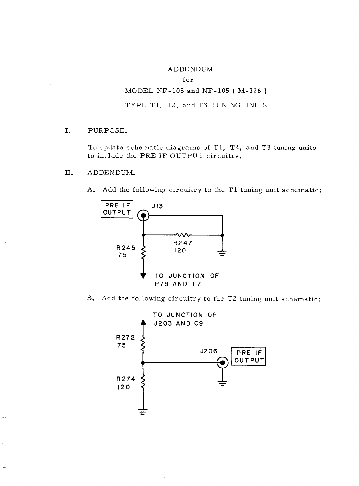
Schematic Diagram of 20 to 200 MC. . . , 95
Tuning lJni-t I-I/NF-105
Schenatic Diagram of 2OOto {OO IvlC . 96
Tuning Uni-t T-2/NF-105
Schematic Diagran of 4OO
to l0O0 MC. . . . . . . . . 97
Tuning Unit T-llNF-105
Schematic Diagram of Basic Measuring Unit 3A-105 . . . . 98
SlockliagranofNF-105.. . o ...99
111

tli
n$:

1.
PARTONE
- IIfTR,ODUCTION
sEcTIoN
I
Descriptlon of Nolse and Fle1d Intensity Meter Model I\F-105
Generaf
Noise and Field Intensity Meter Vodel lS'-105 is lntended for use in the
fiec{tiency range fron 150 KC to lOoO I'b. itrts frequency range is covered
by neans of four plug-f;6;ads;tifCh""liou"e the R. F. and f. F. circults.
The Basic Measurlng Unlt contains detectors and audio circuits, call-
bratlng standards, attenuators and lndlcatlng clrcuits as well as a
voltage regulated power supply. The 150 KC to 20 l0 portlon of this
equipment ls treated 1n a separate book and therefore this book concerns
ltself wlth the 20 Mc to 1oo0 MC
range. rn addition, dlpole antennas,
magnetic, electrlc and line probes, lnjectlon blocks, cables and carrylng
cases are aveilable. Inverters for DCoperation of the equi_pmentra
broad band antenna set and a remote indlcating meter may be had as
optional equlpment.
Appllcatlon
Model I\F'-105
provides a cornpact, llghtweightrportable nolse and fleld
strength rneter for measurements
of nolse originatlng ln electrlcal and
electronlc equipment and of electrical field strength. Bui1t-ln
lmpulse nolse and slne I.Bve generators are used as calibratlng standards
for nolse and carrler measllrenents. Readings maybe taken uslng a
vlsual lndlcator (neter) or aural means (s1ide-back method). Figure 1
lllustrates a typlcal appllcation of the lnstrument.
2.
3, Technlcal Characterlstlcs
POWER
REQUF.I-MEIIIS: I]"5 voltsr 50 to /*00 cycles (tOO VA) or IZ or Zt+
rrolts, Dc (I90 l.Iatts) -
VOLTAOE
RTIGULATTON:
trAft
and frBrr
supply regurated for operatlon fron
105 to 125 volts AC or ll.5 to 15 volts DC (23 to
30 volts DC
respectively).
I?'EQUfi'JCY
RANGEI
150 KC to 10@ MCln four plug-ln heads. Tuning Unit
- f-A/lF'105 treated in a separate bbok, covers the
range fron I_50
KC to.30 16 in six bands; Tunlng
Unlt T-1/l$'-105 covers the range from 20 to 200 I{C
ln two bands; Tuning UnlL T-2/NF-105 covers the
range from 200 to 400 l"l0ln one bend; Tunlng Unit
T-3/Nf-105 covers the range from 400 to 1OOO
MC
in tr.ro bands.

DIPOTE
AMENM \,rV h 4
Y\ | |
ROIARY
MACHINFRY
TOBE
MFASURD
.FIGURE
1 - TYPICALAPPLICATION
OFNF-105

VOLTAGE
RANGEASA TWO-TIRMIML
R. F. V0LTI'{E'I!RI
Interference neasurementsI I to 1O0.COO
nlcrovoltsTl'{C
nTGil BwIMC)
Carrler intensity neasurernents: 1 to IOOrOOO
microvolts
INPIJTIMPIDANCE: 50 ohms
CALIBRATL\GIMPtitSE NOISL SOIIRCE:
fulse repetition rate i 2.5 to 2r5OOcycles
fulse spectrum: Flat to 1000 MC
within lt/Z nA
fuIse anplitude: varlable from 37 to 97 DB above 1 microvolt
per megacycle bandwidth.
INDICATINOMLTER: /*+u logarithnic movenent callbrated in microvolts
(0.5 to 10) and-decibels (-6 to lzo).
WEIGHT: Basic l4easuring Unlt with a Tuning Unit - 71 lbs.
SIZE: Basic Measuring Unit - I8-3/Lt'wide X g|,'hlgh X L/r-5/8n deep.

4. List of Components
Noise and. Field. Intensity I'hter Mode1 llF-105 consists of the components listed
below.
Dinensions (fn. )
Ce.talog No. Height Width Depth
Qran-
tity
l_
1
I
1
a
I
l_
'1
I
]
a
-L
1
I
I
1
l-
l_
l_
z
I
L
I
II
I
1
I
I
1
I
II
t
I
I
1
Il
1
l
I
lI
I
I
Na"neof Component
Basic Measuring Unit (Main Unit )
flining Unit, I5O I(C - 30 l'{C
rr\,rr'r- ITn.'+ cn MC _ 200 l4C
r 41r!!16 vrrr v, Lv
rr\,nin- Irn.i* D^D I.lC _ 4OO l,lc
vrrr v, qv\
Tuning Unit, 400 MC - l0OO MC
R. F. Patch Cord.(6 fuch)
R. F. Patch Cord (18 inch)
AC Line Cord
Standard- Accessory Kit, 2O-1OOO
MC
consisting of the following itens
Accessory Carrying Case
Dipole Antenna Set (20-2oo Mc)
Dipo1e Antenna Set (2OO-4Oot'lC
)
Dipole Antenna Set ()+OO-1OOO
MC)
f -- . \
'I'r1pod (
collapseo /
f -^ , \
Llne rrooe ()u onrns/
l4agnetic Fie1d. Probe
Electric Field. Probe
30 ft. R. F. Cables
Earphones
Alignment Harness
Grounding Strap (: ft. )
Antenna l4asts
l'{ast Socl',et
Liegacycle
RuIe (zo-+oo i'tC)
l,{egacycle
Ru}e ({OO-}O0ClilC)
Broad Ba.nd.
Antenna Cone
Broad Band.Antenna Plane
Tn i aa* i an P] nnle
Broad Band Antenna Rods (Z ft. )
fnverter for 12 V DC Operation
^ ^t.
Inverter for 24 V DC Operation
DC Suppty Cord. (5 ft. )
Renote Ind.icator
Renote Indicator Cable (e> n.)
Line Probe (5OO
ohrrrs)
Carrying Case for Optlonal Equiprnent
Carrying Case for a Tuning Unit
Antenna Equipment for T-:\/NF-lOJ
Switching Unit
Clamp-0n Probe
Filter, 150 KCto ,0 MC
Fll-ter, 20 liC to 65 MC
Filter, 65 MC
to 200 MC
Filter, 2OOMCto 400 }lC
rr 4Pvu ,sb
9-r/2 $4/\ 1\-5
/B
B-r/2 6-r/)+ Lr4/\
B-t/z 6-t/\ rL4/I+
B-r/2 6-r/t+ l-1.3/t+
B-t/z 6-t/\ tt-Z/t+
I[-r/t+ 4i/)+ 7
/a
bbl
>-t /z a,-t
/> z-t />
J -/ - J -l'
2011
t-3/\ r-L/z r-r/z
9-r/2 B B
r/2 d+ d+
2 2-L/2 1
6-3/\ e-7
/B 5-5/B
6-3/4 9-7
/B ,-,/B
tr-t/2 )+-r/8 t+-r/z
>-t />
i.'-'r7r,
ro-L/2
6
r,-l /A
1 1/A
L_L/,+
5-a/B
)-)/,4
5-1/,8
5-t/B
5
BA-105
m A,/ntr. i.\tr
t -^f ,trL - Lv )l
T-1lr\IF-105
r-p /tm'-tos
.. -/ _
- -'/
m :/nrr tn<
L- J/ LvL -Lv)
r0-r05-D
AC-10
5-
C
DM-rO5-T1
DM-1O5-T2
DM-105-T3
rnp-t
oq-A
Lv ) --
LL-r05
I\,tr-I05
EP-r0
5-A
cB-105
EA-rO5
AH-1O5
GR-r05
I'fA-105
I\.le 1r\tr A
t'D-Lv)-n
BB-105
BB-105
uN-lo5
BB-105
r,1012-105
i'tO2lr-105
DC-105
RE-1O5
DA 1^tr
T ar 1 /\tr
ttr-Lv)
0c-r05
mn 't ntr
f,lvl-10
5
su-]05
cP-105
R- a,/Nn-toc
F-rAlNF-
r-05
r-rB/NF-r05
F-2lNF-105
BG-
10
5
I4-1/r+ ar4/\ 7
t+-t/z zr-r/z 3-r/z
t+-r/z zr-r/z 3-r/2
t+-t/z zr-r/2 3-r/z
2I-5/B t+ 3-t"/\
3 2-r/2 2-L/2
ro 3-L/2 r
7
-j/e j/B 5/e
aAa/^
J 1-L/1
25-r/2 zB-t/t+
Lr-'L/2 7-3/\
14 rr-r/2
t-)/E r-t/,8
4-1/e 2-r/,2
4-r/B )-1/,8
4-r/,8 1-t/,8
4-r/e 1-1/B
q:r/8 1-1/B
104

s* '&s&ss
*; $****
T.
,
:
,'";
*g
g3
f* s
*a
:$;s$
$g
;*s$
s
urrEFe.blF:o-l-
:e{9(,};ts{$$e
**Oeif.((}lrl
J:r'{}.F.4gJ>
rdl rf,r sl
(} {}(?;
T TT
e 33
{
'.1'
r$1
Q
l.
&
l4S
gHH
-,,.i
??T
ff
trsEs*
HH *-*
s fi [ ss s*
2 i : fi -::* n*
Z 3 X**,Sd;i
g Eg
irr bJr*l*r{J0a $q:.FA-
*g$$$$3s6ii:qi$
6 a-opr#f
:?d;$
X$$$*;$$ng5*x*;
S. (:) o- (},r"S I5 u J (} *r.t .( d) tj a
:$J JdU -cd'l,r "d
J <. J J J r{;
g3;(35J*s; g raj { g b.} {,) g :E J
ffTE I
rF$*a
tri
:1.
u
&
to
I
:*,
s8
s{e
$.
*ii*
f
t*a
$$$$H''$
*s
* (,,
**i'ffi
*;fi j H,
Wr$;$;p
$
,f;
gu;[s
n6
g ggt;
I 83S
T\J
A&?
R
*
&37
!{*YgY
t5 * r-
t,
+"*'a
:) : 3:p 3,
(,:E $('tr,
z$ &e.a'
- F- ;' -; i;:
A.-.2*t'
:piB l]:'p
'::l*
.
rt
,rtS
.t#.
*
rS
dr
.'ln:
F
r
i.:i:
I,
&
'{m'
Sr q' r*6{Fg:!
rry ftl tq c{'$)


COMPARTMENI
FOR
- 8I I}IVIRTiR CABLE
- 251 RLMOTE
MTTIRCABLE
RII',IOTE
MITIR
ANTENM},!ASTS
(6)
FIGIJRE
3 - ARnANGEMbT
0F PARTS
IN
TRANSITCHMT
SPARE
PARTS
TRAY
SPAREPARTS
BROAD
BAND
AIITENM CONE
IIVViRTM
BAI{D
ANTENMBASE
I
I
OPTIOML EQUIPME}N

5. Descrlptlon of l'la1or Components
The Besic l4easuring Unlt of Noise and Field Intenslty Meter Model NF-105,
ln conjunction wlth the R. F. plug-in heads, contains all tubes and
assoclated circuits. It ls housed in an aluminum cese provided with a
gasketed front cover.
Of the f'our R. F. plug- j.n heads ava
i lable, one is norrnally carried
plugged into the main unit. The other three R. F. plug-in heads
may
be individually stored in carrying cases 1or tuning unit (TC-105).
For three of the tunlng heads (T-1/Nf-105, T-2/NF-105 and T-3/l,IF-Io5),
there is a corresponding dlpole antenna set consisting of a balun trans-
former and dipole arms. A mounting base and three extension mast rods
are provided to nount any of the dipole antennas on the tripod.
Antennas
for Tuning UnitI'-A/NI'-fOS are covered in a separate section.
The broad band antenna consists of a cone equipped with fittings for
extenslon rods, 6 extension rods and a ground plane.
A11 antennas may be mounted on an adjustable wooden tripod.
The magnetic field probe consj-sts of a three-inch electrostatically
shielded pick-up loop attached to a handle. In order to minimlze shock
hazard, the probe is insulated.
The el-ectric field probe consists of a pick-up rod housed in a contalner.
r:r'^ +L^ -^--+ jn ficld nrnhe t.his nrohe is insufaLed.
LlnE u11g rriotlllYUIU rrctu Pf uug, vrlro prvuL to lrlo
Four fllters are available as ortional itt--ns to ploviic a means of re-
jecting any sin5le f requency desired f rom .}50 XC to 4oO It{C.
The two linc probes differ in that one i-s a 5O ohrn
and tlte othor a )OO
ohrn
pick-up device. Each probe ls hcused in a shjcld and is cquipped
uriih hirdinrr nosts for easy attachment to thc ljnc to be evaluated. The
probe is capaciti-ve1y coupleC to lhe line. A clamp-on probe is also
avail-able for taklng conCuctive mcasurcrncnts.
The renote indicator contalns a meter duplicating that on the main instru-
rnent panel. An earphone Jack is provided to faciLlta+,e aural monltoring.
The DC inverters are of the rotary type furnlshing the 115 volts 60 cycle
power needed to operate the equipment.
The headset is designed for 60O ohrns impedance.
An injection block is provided for use with the broad band antenna.
A grounding straq serves to protect the operator from electrical shock
when touchinE the equiPment.
An allgnment harness is provided for R. F. and I. F. alignment of the plug-
in heads. It consists of two small metal containers housing the appropri-
ate circults, connecLors and connecting leads.
S*l bching unit Sil-10! enables the oper':tor to f eed eithcr th<-'
caf ibrating
signal frcm the Impulse Generator or the interference si-gna1 frorn the
antenna to the Siclliil, IIiii'U? jack on thc front panel by means of a toggle
svritch rather than by changing cables. This unit |s available as an
accessory.

6.
SECTION
II
fnstallation and Aseembly
Selectlon of Slte
When
setling up the equipment for interference measurements, it should
be so located that the appropriate antenna or probe can reach the
interference source when connected through the 3o-foot length of R. F.
cable. 't{hen
using the equipment for field lntenslty measurements, a
site must be chcsen which ls free frorn trees, electrical nrr.rer
and
telephone lines, netal fences, brrildlngs and other projectlons that
might interfere r,rith the field strensth pattern.
Assemblv and Interconnections
Ascertain that the plug-in head covering the desired frequency range is
lnserted ln the main unit. If not, loosen the head latch located near
the left edge of +,he
nain paner (see Figure /*), Holding back or locking
the ]atch to cl-ear the panel of the plug-in head, puil the handle
l-ocaled near the left edge of the plug-in head. fnsert the head coverlng
the desired frequency range in lhe main unit, again holding the lstch
of the locking mechanlsm. After fu11y inserting the head, release the
latch which will then rest against +,he
front of the plug-in head panel.
Tighten the locking screw. Remove
from the accessory carrying case such
additional componentsas may be required, including the following:
s. R. F. patch cord - 6 inches. Connect thls cord between the ATTEN.
OUTPUT
connector near the left edge of 'uhe
equipment panel and the
connector on the pl-ug-in head; if lhe head used has 4ore than one
frequency range the cord must be attached to the connector corres-
ponding to the frequency range deslred.
o
b. R. F. patch cord - 18 inches. This cord
tion to connect the IlfUlSE GEN. or SfNi,
INPUT
receptacle.
is used with shunt calibra-
JA'/E GEN. to the SIGML
c. AC line cord. This cord leads from the AN connector located on the
right side of the equlpment penel (beneath the fuse post) to ttre tt5
volts t 50 Lo d00 cycles polrer source.
d. Inverter. lf the equlpnent is to be operated fron a battery, the
inverter correspondlng to the available DCvoltage (12 or 21,
V) is
used. Connect the free end of the AC power cord to the outlet on
the side of the inverter.
€o DC power cord. By means
of the DC por.rer
cord, connect the inverter
to the battery. If the battery is part of a grounded system, always
connect the black lead of the DC polrer cord to the grounded terminal
of the babtery, regardless of the battery polarity.

6N PArcH
CCND
SIIIICHING UNTT >
su-105 CREEI{
+
2< Fr BATIEnY
' 12Vor 2L\
(not furnished)
It5 VC[,TS
5oto /+oocrrlrs
CR
PHONES
PHONES
FT. CABLES
TO GROII'DM
cOr,tDuIT
cR
CROU'D
STAIG
FIGTJRE
4 -INTTNCONI.IECTIOIJ
BETWEts]{VARI
OUSC
O"IPONENTS
DIPOLE
ANIE)IM
10
Table of contents
Popular Measuring Instrument manuals by other brands

Precision Digital Corporation
Precision Digital Corporation Survivor PD662 instruction manual

evertz
evertz ATOM-Box user guide

Storch
Storch HPM clima operating manual

KROHNE
KROHNE OPTIMASS 6400 Supplementary instructions

Keithley
Keithley 2651A Reference manual

LAUMAS
LAUMAS WDESK-LIGHT Installation and user manual