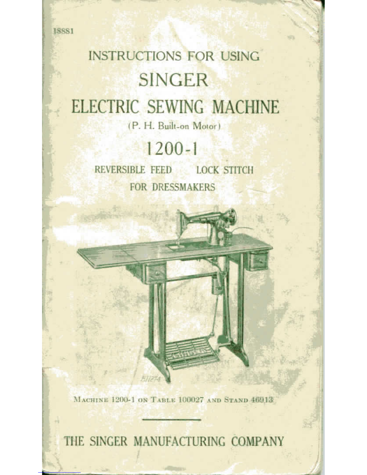
Singer 1200-1 User manual

INSTRUCTIONS
-OR
US1NC
IN.GER
SEWING
Built-on
[
1200-1

To
'ill
whom
itmay
concern:
The
placing
or
renewal
ofthe
name
"Sing-.
pr"
Reg.
U.S.
Pat.
Off.
i
oranyofthe
trade
marks
ofThe
Singer
Manufacturing
Com-
pany
onany
machine
that
has
been
repaired,
rebuilt,
reconditioned,
or
altered
in
any
way
.-'»••
**".•..•
.
„;
whatsoever
outside
a
Singer
factory
orah
authorized
Singer
agency
is
forbidden.
Genuine
Cinder
Needles
should
be
used
in
SingerMachines.
TheseNeedles
and
their
Containers
are
markedwith
the
Company'sTradeMark
"SIMANCO."
1
Needles
in
Containers
marked
"ForSinger
Machines"
arenot
Singer
made
needles.
i
Copyright,
U.S.
A.,
1915,
1920,1921,1923,
I&24.
1928,1931,
1932,
1933,1935
and
1936
_.-
by
The
Singer
Manufacturing
Co.
All
Rights
Reserved
forall
Countries
*T
"

INSTRUCTIONS
FOR
USING
SINGER
,
;
ELECTRICSEWINGMACHINE
(P.
H.
Buili-on
Motor
I
1200-1
REVERSIBLE
FEEDLOCK
STITCH
FOR
DRESSMAKERS
MACHINE
IL'OO-l
ONT
un.i-:
KNX127
AVD
THE
SINGERMANUFACTURING COMPANY

-
Description
Machine
1200-1
is
especially
suited
for
dress-
makers
and
homeindustrial
use.
Itis
used
on
Table
1(K)027
and
Stand
46913,
as
shown
on
page
1,andis
fitted
with
a
knee
lifter
for
raising
and
lowering
the
prosper
foot.
The
machine
is
driven
byan
electricmotor
built
on
the
back
ofits
arm,
and
controlled
bya
treadle.
An
electric
Singerlight
is
also
built
on
the
armto
throw
light
onthe
work.
The
machine
hasa
horizontal
rotary
sewing
hook
and
makes
the
lock
stitch.
7t
has
reverse
feeding
mechanism
by
means
of
which
the
machinestitches
as
readily
ina
reversedirection
asit
does
ina
for-
ward
direction.
FIG.
2.
REAK
VIEW
OF
MACHINE,
.MriT'iii
\NT>
PKKJWKR
BAK
LUTING
LKVKR
B.
C
D
E
j,
FIG.
3.
UNDEHSIDB
OK
TABLE,
SHOWINU
DHII*
PAN
AND
K.vtK
LIFTER
The
knee
plate
(D,
Fig.
3)maybe
moved
upor
down
to
suit
the
operator
after
loosening
the
set
screw
(E).
It
maybe
swung
tothe
right
or
left
after
loosening
theset
screw
in
the
hub
(B).
The
stop
(C)
should
be
set
so
that
the
knee
lifter
cannot
raise
the
presser
barany
higher
than
itis
raised
by
the
hand
lifter
(A,
Fig.
2),in
order
to
pre-
vent
strain
onthe
tension
relea.se
mechanism.
Thc
rear
stop
(F,
Fig.
3)
should
permit
a
little
loose
motion
ofthe
knee
lever
after
the
presser
foot
has
beenlowered
tothe
throat
plate.

r
Motor
Canbe
Operated
on
Either
Alternating
Current
or
Direct
Current
The
electric
motor,
which
is
located
atthe
back
of
the
machine,
canbe
operated
on
either
alternat-
ing
current
or
direct
current,
as
desired.
The
standard
windings
ofthe
motor
arefor110
volts,
but
motors
canbe
furnished
for
any
voltage
be-
tween
100and
250.
Special
motors
for32
volts
direct
current,
and
for
oO
voltsalternatingcurrent
and
directcurrent,
have
also
been
developed
andare
available.
Points
to
Determine
Before
Connecting
Motor
to
Electric
Service
Line
Obtain
the
following
information
from
the
Elec-
tric
LightCompanywhich
supplies
the
electric
current
forthe
circuit
to
which
the
motor
isto
be
connected:
1.
If
current
is
direct,
what
isthe
voltage?
The
voltage
range
stamped
on
the
nameplate
ofthe
motormustcorrespond
to
that
ofthe
circuit.
2.
If
current
is
alternating,
in
addition
to
the
voltage,what
isthe
number
of
cycles?
The
number
of
cyclesstamped
en
the
name
plate
ofthe
motor
mustcorrespond
to
that
ofthe
circuit.
The
voltage
ofany
circuitand,
if
alternating
current,
the
number
of
cycles,
canbe
verified
by
looking
at
the
name
plate
on
service
watt
meter
installed
by
the
local
Klectric
Light
Company.
To
Connect
the
Machine
to
Electric
Service
Line
Push
the
terminal
plug
atoneendofthe
electric
cord
asfarasit
will
goonthe
three-pin
terminal
block
atthe
right
ofthe
machine,
as
shown
in
Fig.
7.
Attach
the
plug
atthe
other
endof
the
cord
tothe
nearest
electric
outlet
and
the
machine
is
ready
for
operation.
To
Insure
Perfect
Action
of
the
Machine
When
turned
by
hand,
the
balancewheel
must
always
turn
overtoward
the
operator.
Donotrunthe
machine
with
the
prcsser
foot
resting
onthe
feed
withoutclothunder
the
presser
foot.
Donotrunthe
machine
when
both
bobbincase
and
needle
arc
threaded,
unless
there
is
material
under
the
presser
foot.
Donottryto
help
the
machine
by
pulling
the
fabric,
lest
you
bend
the
needle.
The
machine
feeds
the
work
without
assistance.
The
slideover
the
bobbin
case
should
be
kept
closed
when
the
machine
isin
operation.
CAUTION
When
you
have
finished
your
sewing,alwaysdis-
connect
the
plug
from
the
electric
outlet.

r
Singerlight
To
turn
the
Singerlight
"on"
or
"off",
a
switch
is
conveniently
located
atthe
front
of
the
three-pin
terminal
block,
as
shown
atD,
Fig.
7.
To
Remove
and
Replace
the
Bulb
Do
not
attempt
to
unscrew
the
bulb.
Itisofthe
bayonet
and
sockettype
and
does
not
unscrew.
Fid.
4
To
Remove
the
Bulb.
Press
the
bulbinto
the
Singarlight
socket
andatthe
sametimeturn
the
bulbover
toward
the
machine
asfarasit
will
go,
then
withdraw
the
bulb.
To
Insert
a New
Bulb.
Press
the
bulbinto
the
Singerlight
socket
and
turn
it
over
from
the
machine
until
the
bulb
pin(A,
Fig.
4)
enters
the
notch
inthe
socket,
as
shown
in
Fig.
4.
To
Operate
the
Machine
Raise
the
presser
foot
(B)by
means
of
the
presser
bar
lifter
(C)to
prevent
injury
tothe
foot
(B)and
feed
(A).
I-'IG.
5.END
VIEW
IIF
THE
MACHINE
Place
a
piece
of
clothunder
the
presser
foot
and
let
the
foot downupon
it.
Turn
on
the
electric
current
and
depress
the
treadle.
Asthe
pressure
on
the
treadle
is
increased,
the
speed
of the
machine
is
increased,
the
speed
being
controlledentirely
bythe
amount
of
pres-
sure
onthe
treadle.Operate
the
machine
hi
this
way,
without
being
threaded,
until
you
have
be-
come
accustomed
to
guiding
the
material
and
operating
the
treadle.

r
To
Remove
the
Bobbin
Draw
tothe
left
the
slide
inthebedofthema-
chine
and
lift
outthe
bobbinwith
the
thumb
and
forefinger
ofthe
left
hand,
as
shown
in
Fig.
6.
FIG.
C>.
HEMOVIXG
THE
ROBBI\o
Wind
the
Bobbin
Itis
necessary
to
understand
the
stop
motion
(C,
Fig.
7}by
which
the
balancewheel
(B,
Fig.
7)
canbe
released
when
required,
thuspermitting
the
winding
of
bobbinswithoutrunning
the
stitching
mechanism.
Release
the
balancewheel
by
turning
the
stop
motion
screw
(C)
overtowardyou.
It
is
necessary
to
hold
the
balance
wheel
while
loosening
the
stop
motion
screw.
"
9
Place
the
bobbin
onthe
bobbinwinderspindle
und
push
itup
closelyagainst
the
shoulder,
having
FIG.
7.
WINDING
THE
BOBBIN
the
small
pininthe
shoulder
enter
the
hole
inthe
side
ofthe
bobbin.
Putthe
spool
of
thread
onthe
spool
pin
(1).
Draw
the
thread
under
and
between
the
tension
discs
(2)onthebedofthe
machine,
then
pass
the
thread
upand
through
the
hole
(3)
in
the
leftside
ofthe
bobbin,
from
the
inside.
Press
down
onthe
bobbin
andthe
bobbinwinder
latch
(A,
Fig.
7)
will
dropdown
and
hold
the
bobbin
winder
pulley
against
the
hubofthe
balancewheel.
Then
press
the
treadle
the
same
asfor
sewing.

r
10
Theendofthe
threadmust
be
held
bythe
hand
until
a few
coils
are
wound
and
shouldthen
be
brokenoff.
When
sufficient
thread
has
beenwound
upon
the
bobbin,
the
bobbin
winder
is
automatically
released
from
the
balance
wheel.
FIG.
8.
ADJUSTMENT
OF
BOBBIN
WINDER
If
the
pressure
ofthe
bobbinwinderpulley
against
thehubofthe
balancewheel
is
insufficient
for
wind-
ing
the
bobbin,
pressdown
the
bobbinwinderuntil
the
latch
(A)
dropsdown
and
holds
it,
then
loosen
the
adjustingscrew
(F).
With
the
forefinger,
push
back
the
upper
endofthe
slotted
plate
(E)asfar
asit
will
go,as
shown
in
Fig.
8,andatthe
same
time
press
the
bobbin
winder
pulleyagainst
thehub
of
the
balancewheel,thentighten
the
adjusting
screw
(Fj.
If
the
threaddoes
not
windevenly
on
the-
bobbin,
loosen
the
screwwhichholds
the
tensionbracket
(2,
Fig.
7)in
position
onthebedofthe
machine
and
slide
the
tension
bracket
tothe
right
or
left,
asmay
he
required,thentighten
the
screw.
Bobbins
can
also
be
wound
while
the
machine
is
sewing.
•
11
To
Replace
the
Bobbin
and
Thread
the
BobbinCase
Hold
the
bobbinbetween
the
thumb
and
fore-
finger
of
the
left
hand,
the
thread
drawing
onthe
bottom
from
right
to
left,
as
shown
in
Fig.
<).
120932
FIG.
0.
REPLACING
THE
BOHHIN
Place
the
bobbin
inthe
bobbin
case
and
draw
the
thread
into
the
slot
(1,
Fig.
10)inthe
bobbin
case,
as
shown
in
Fig.
10.
£1129^
I
Fin.
10.
THREADING
THE
BOBBIN
CASE

F
L2
Draw
the
threadtoward
you
between
the
bobbin
case
andthe
tension
spring
until
it
passes
the
notch
(2,
Fig.
11)inthe
bobbincase,
as
shown
in
Fig.
11.
13
To
Set the
Needle
Turn
the
balancewheel
over
toward
you
until
the
needle
barisatits
highestposition,
and
loosen
the
thumbscrew
(A,
Fig.
13)inthe
needle
clamp
FIG.
11.
BOBBIN
CASE
THREADED
Then
close
the
slide
andatthe
same
timedraw
the
threadinto
the
longnotch
inthe
right
edge
of
the
slide,
as
shown
at(3,
Fig.12).
FLAT
SIDE
FIG.
13.
POSITIONING
or
N
IN
NUKDLE
CLAMP
Have
theflat
side
ofthe
shank
ofthe
needletoward
the
left
as
shown
above
and
put
the
needle
up
into
the
clamp
asfaras
it
will
go.
Then
tighten
the
thumb
screw.
FIG.
12.
UNDER
THREADING

14
UpperThreading
(SEE
FIG.
14)
Turn
the
balance
wheelovertoward
you
until
the
threadtake-uplever
(5)is
raised
toits
highest
point.
Place
the
spool
of
thread
onthe
spool
pin
atthetopofthe
machine-
and
pass
the
thread
to
the
left
through
the
thread
guide
(1),
down,
under
and
from
right
to
left
between
the
tensiondiscs(2).
With
the
righthandhold
the
spool
to
prevent
it
from
turning,
and
with
the
left
handdraw
the
thread
up
into
the
take-up
spring
(4)
until
the
thread
enters
the
retaining
fork
(3),
then
pass
the
thread
from
right
to
left
through
the
hole
inthe
thread
take-up
lever
(5),
downthrough
the
guide
(6)
on
the
face
plate,into
the
wire
guide
(7)onthe
needle
bar
bushing,into
the
guide
(8)onthe
needleclamp
and
from
right
to
leftthrough
the
eye(9)of
the
needle.
Draw
about
two
inches
of
threadthrough
the
eye
of
the
needle
with
which
to
commence
sewing.
15
£11700
VlG.
14.
Ul'PER
TlIUEADIXG

16
To
Prepare
for
Sewing
Witli
the
left
hand
hold
the
end
ofthe
thread,
leaving
it
slack
from
the
hand
to
the
needle.
Turn
FIQ.
15.
DBA
wise
UPTHE
BOBBIN
THREAD
the
balance
wheelovertoward
you
until
the
needle
moves
down
andup
again
toits
highest
point,
thus
catching
the
bobbin
thread.Draw
up
the
needle
thread
andthe
bobbin
thread
will
come
up
with
it
through
the
hole
inthe
throatplate,
as
shown
in
Fig.
15.Lay
boththreads
back
under
the
presser
foot
and
close
the
slide.
To
Commence
Sewing
Place
the
materialbeneath
the
presserfoot,
lower
the
presser
foot
and
commence
to
sew.
When
sewing
thick
material,
itmaybe
necessary
to
turn
the
balance
wheel
overtoward
youby
hand
to
start
the
machine.Thisshouldalso
be
done
ifthe
machine
stops
when
sewing
across
thick
seams.
17
To
Remove
the
Work
Stop
the.machine with
the;
thread
tako-up
lever
(5,
Fig.
14)atits
highestpoint,
raise
the
presser
foot
and
draw
the
fabric
back
andtothe
left,
pass
the
threadsover
the
threadcutter
(A,
Fig.
15)and
pull
down
lightly
to
severthem.
Leave
the
ends
of
the
threadsunder
the
presserfoot.
To
Turn
a
Corner
Stop
the
machinewhen
the
needle
isatits
lowest
point.
Raise
the
presserfoot
and
turn
the
work
as
desired,using
the
needle
asa
pivot,thenlower
the
presser
foot.
To
Regulate
the
Pressure
onthe
Material
For
ordinary
family
sewing,
itis
seldom
necessary
to
change
the
pressure
on
the
material.
If
sewing
fine
silk
orflimsy
material,lighten
the
pressure
by
turning
the
thumbscrew
(C,
Fig.
32)
onthetopof
the
machineover
tothe
loft
so
that
it
screws
up.
To
increase
the
pressure,
turnthisthumbscrewover
to
the
right
so
that
it
screwsdown.
The
pressure
should
be
onlyheavyenough
to
prevent
the
material
from
rising
with
the
noodle
andto
enable
the
feed
to
move
the
workalongevenly.
The
heavier
thema-
terial,
the
heavier
the
pressure;
the
lighter
the
material,
the
lighter
the
pressure.

18
To
Regulate
the
Direction
of
Feed
To
feed
the
goods
from
you,
push
down
the
stitch
regulator
lever
(B,
Fig.
16)as
far
asit
will
go.
FIG.
16.
SHOWING
LEVER
FOE
REVERSING
DIRECTION
OF
FEED
AND
REGULATING
LENGTH
OF
STITCH
To
feed
the
goods
toward
you,
raise
the
stitch
regulator
lever
(B)as
high
asit
will
go.
The
direction
of
feed
can
be
reversed
atany
point
of
a
seamwithoutremoving
the
work
from
the
machine.
Back
tacking
is
therefore
readily
accomplished
and
the
fastening
ofthe
ends
of
seams
is
made
easy.
19
To
Regulate
the
Length
of
Stitch
The
machine
canbe
adjusted
to
make
from
6 to
30
stitches
tothe
inch
as
indicated
bythe
numerals
on
the
stitchindicator
plate
(C,
Fig.16).
The
number
of
stitches
tothe
inch
that
the
machine
issetto
make
is
indicated
bythe
number
which
isin
line
with
the
upperside
ofthe
stitch
regulating
lever
(B,
Fig.
16).
To
change
the
length
of
stitch,loosen
the
thumb
screw
(AT
Fig.
16)and
move
ittothe
bottom
of
the
slot.
Thenmove
the
stitchregulatinglever
(B)
until
its
upperside
isin
linewith
the
number
ofthe
desired
length
of
stitch.
Now
move
the
thumb
screw
(A)
until
the
stitch
regulating
plate
touches
the
lever(B),then
tighten
the
thumbscrew(A).
The
machine
will
make
the
same
number
of
stitches
tothe
inch
in
reversedirection
when
the
lever
(B)
is
moved
toits
highestposition.
Should
forward
stitching
only
be
necessary,
move
the
screw
(A)
down
tothe
bottom
ofthe
curvedslot
and
firmly
tighten
it.The
length
of
the
forward
stitch
can
then
be
changed
by
moving
the
lever
(B)
downward
fora
long
stitch
or
upward
for
a
short
stitch-
In
this
case
the
lovershould
not
be
raisedhigherthan
the
top
line
inthe
scale.
Basting
The
longest
stitch
made
bythe
machine,
Xo.
C>
onthe
stitchindicator,
is
found
satisfactory
for
basting,
after
loosening
the
tension
onthe
needle
thread
so
that
the
stitches
maybe
easily
pulled
from
the
material.
Machine
basting
is
firmerand
more
even
than
thatdone
by
hand
in
addition
to
being
muchquicker.
ToSew
Flannel
or
Bias
Seams
Use
a
short
stitch
and as
light
a
tension
as
possible
on
the
needle
thread
soasto
leave
the
thread
loose
enough
inthe
seam
to
allow
the
goods
to
stretch
if
necessary.

20
Tensions
For
ordinarystitching,
the
needle
and
bobbin
threads
should
be
locked
inthe
centre
ofthe
thick-
ness
of
the
material,
thus:
Fiu.
17.
PERFECT
STITCH
If
the
tension
onthe
needlethread
istoo
tight,
or
if
that
onthe
bobbinthread
istoo
loose,
the
needle
thread
will
lie
straightalong
the
upper
surface
of
the
material,thus:
Fiu.
IS.
TIGHT
XEEDLE
THREAD
TENSION
If
t.hc
tension
on
the
bobbinthread
istoo
tight,
or
if
that
onthe
needle
thread
istoo
loose,
the
bobbin
thread
will
lie
straight
along
the
underside
ofthe
material,
thus:
FIG.
19.
LOOSE
NEEDLE
THKEAD
TENSION
B
To
Regulate
the
Needle
ThreadTension
The
tension
onthe
needle
thread
canbe
regulated
onlywhen
the
presser
foot
is
down.
The
tension
index
flange
(D,
Fig.
20)is
marked
witharbitrary
numbers
ranging
from
1to9
which
indicate
different
degrees
of
ten-
sionthat
canbe
pro-
duced.
The
numbers
do
not
denote
the
amount
of
tension
ora
par-
ticular
size
of
thread.
By
noting
the
number
which
is
opposite
the
FIG.
20.
NEEDLE
THREAD
TENSION
pointer
Oil
the
indica-
tor(G)
when
setfora
satisfactorytension
onthe
work
being
stitched,
the
number
canbe
readilyreverted
to
when
a
change
is
made
inthe
tension
or
size
of
thread.
To
increase
the
tension,
turn
the
thumb
nut
(B)
over
tothe
rightuntil
the
desired
number
on
the
index
flange(D)is
opposite
the
pointer,
the
higher
numbersdenotingincreasedtension.
To
decrease
the
tension,
turn
the
thumb
nut(B)
over
tothe
left,
the
lower
numbers
indicatingless
tension.
The
tensionindicator
(G)is
markedwith
the
signs
+and
—,
whichalsoindicatewhichdirection
to
turn
the
thumb
nut
(B)for
more
or
less
tension.
To
Regulate
the
Bobbin
Thread
Tension
The
tension
onthe
bobbinthread
is
regulated
by
the
screw
(C,
Fig.
11)inthe
bobbin
case
tension
spring.
To
increase
the
tension,
turn
the
screw
(C)
overtowardyou.
To
decrease
the
tension,turnthis
screw
overfromyou.
When
the
tension
onthe
bobbinthread
has
been
once
properly
adjusted,
itis
seldom
necessary
to
change
it, as a
correct
stitch
can
usually
be
obtained
by
varying
the
tension
onthe
needle
thread.

To
Remove
and
Disassemble
the
Needle
Thread Tension
Loosen
theset
screw
(A,
Fig.
21)and
withdraw
the
complete
tension
assembly
from
the
machine.
Turn
the
thumb
nut
(B,
Fig.
22)
until
zero
onthe
indexflange
FIG.
21
(D)
is
opposite
thepointeronthe
indicator(G),
then
press
in
the
index
flange
(D)
to
disengage
the
pin
(C)inthe
thumb
nut(B)
from
theflange
and
remove
the
thumb
nutandflange,theflange
stopwasher
(E,
Fig.
23),tensionspring(F),indicator
C
B
FIG.
23
(G),
tension
releasing
pin
(J),
and
tensiondisc
assem-
bly
(II),
which
includes
the
thread
take-np
spring,
thread
guard
plate
andtwo
discs.
23
FIG.
24
To
Reassemble
and
Replace
the
NeedleThread
Tension
Place
(hetwo
tension
discs
(T-,
Fig.
24)
with
then-
convex
sides
(high
centers)
facing
each
other
in
posi-
tion
onthe
thread
guard
(M).
Then
pass
the
eyelet
(N)
of
the
thread
take-
up
springunder
the
thread
guard
(M),
having
the
coils
of
the
spring
above
the
tension
discs,
as
shown
in
Fig.
24.
Pass
the
threaded
end
(O,
Fig.
25)ofthe
tension
stud
through
the
coils
ofthe
take-up
spring
(P),
through
the
holes
in
thetwo
tension
discs
(L)
and
thread
guard
(M),
and
through
the
eyelet
(X,
Fig.24)ofthe
take-upspring,
having
theendof
the
take-up
springenter
one
ofthe
grooves
(Q)
inthe
stud.
Thenplace
the
tension
releasing
pin
(J)
inthe
tension
stud.
26
Hold
the
parts
thus
assembled
against
the
shoulder
on
the
stud
and
place
the
tension
indicator
(G,
Fig.
20)

24
on
the
stud,theninsert
the
tension
spring
(F)in
the
indicator
with
the
first
half-turn
ofthe
spring
below
(he
stud
or
away
from
the
pointer
ofthe
indi-
cator
as
shown
in
Fig.
26.
Xmv
place
index
flange
stop
washer
(E)on
t
lie
stud
\vii
h
its
extension
toward
the
indicator
pointer
asin
Fig.
26.if
spring
and
stopwasher
arein
correctposition,
the
extension
(S)
will
clear
thefirst
coil
ofthe
spring
as
shown
in
Fig.
27.
Place
index
flange(D,
Fig-
26)onthe
stud,
turn
it
so
that
the
number
1 is
opposite
the
pointer
on
the
tensionindicator
((".),
and
press
it
inward
until
the
thumb
nut
(15)
canbe
turnedonto
the
slud.
Try
engaging
thepin(C)in
different
holes
intheflange
until
oneis
found
which
permits
the
full
range
of
tensions
from
light
to
heavy
to
be
produced
with
one
revolution
ofthe
thumb
nut.
FIG.
27
Lower
the
presser
barto
relieve
the
pressure
on
thepin(J,
Fig.
26).
Replace
the
complete
tension
assembly
inthe
machine,having
the
long
lug
(K,
Fig.'
25)
enter
the
hole
(U,
Fig.28),
the
pointer
(G,
Fig26)atthe
top,
andthe
threadtake-up
spring
resting
onthe
regulatorplate
at(V,
Fig.28),
as
shown
in
Fig.
20.
Push
the
complete
tension
in
asfarasit
will
go,
then
firmly
lighten
the
set
screw
(A).
The
tension
onthe
thread
take-upspring
(T,
Fig.
26)
should
be
just
sufficient
to
take
upthe
slack
of
the
needle
thread
until
theeveofthe
needle
reaches
25
the
goods
inits
descent.
A
slightvariation
inthe
tension
on
the
take-up
spring
maybe
secured
by
loosening
theset
screw
(A,
Fig.
28)
and
turning
the
tension
stud,
with
the
indicator
(G,
Fig.26),
to
the
left
formore
tension
orto
right
for
less
tension.
However,
ifthe
correct
tensioncannot
be
secured
without
turning
the
indicator
pointer
(G)toa
posi-
tion
inconvenient
to
read,
remove
the
assembly
from
the
machine,
disengage
theendofthe
spring
from
the
groove
(Q,
Fig.
2o)
inthe
tensionstud,
revolve
the
spring
and
place
its
end
inthe
groove
which
produces
the
correcttension.
U
FIG.
28
Ordinarily,
the
tension
onthe
needlethread
is
regulated
by
turning
the
thumb
nut
(11,Fig.26),
butifthe
requiredtensioncannot
be
produced
by
this
means,
adjust
the
tension
as
follows:
Press
in
the
index
flange(D,
Fig.
26)to
disengage
the
pin(C)
in
the
thumb
nut(B)
from
theflangeand
reset
the
pininoneofthe
otherregulating
holes
intheflange,
turning
the
thumb
nut
inwardly
to
increase
the
tension
or
outwardly
to
decrease
it.

2(1
HINTS
Machine
Working
Heavily.
Ifthe
machine
runs
hardafter
standing
idle
for
some
time,
usea
little
kerosene
inthe
oiling
places,
runthe
machine
rapidly,
then
wipe
clean
and
oil.
See
following
pages.
To
Avoid
Breaking
Needles.
See
that
the
prcsscr
foot
or
attachments
arc
securelyfastened
by
the
thumb
screw.
Donotsew
heavyseams
or
very
thick
goods
with
toofinea
needle.
A
large
needle
and
thread
to
correspondshould
be
used
on
heavy
work
(see
page
61).
See
that
the
needle
isnot
bent
and
avoidpulling
the
materialwhenstitching.
Breaking
of
Needle
Thread.
If
the
needle
thread
breaks
itmay
be
caused
by:
Improperthreading.
Tensionbeing
too
tight.
The
threadbeing
too
coarse
for
size
of
needle.
The
needlebeing
bent,
having
a
bluntpoint,
or
being
set
incorrectly.
Breaking
of
BobbinThread.
If
the
bobbin
thread
breaks
itmaybe
caused
by:
Improper
threading
of
bobbin
case.
Tension
being
too
tight.
Skipping
of
Stitches.
The
needle
maynotbe
accurately
set
into
the
needle
baror
the
needle
may
be
blunt
or
bent.
The
needle
maybetoo
small
or
too
large
forthe
thread
in
use.
Free
Instruction
for
using
the
machine
is
gladly
given
atany
SingerShop.
27
To Oil the
Machine
To
insure
easy
running,
the
machinerequires
oiling
andif
used
continuously
it
should
be
oiled
FIG.
29.
FRONT
VIE.V,
SHO\VI.\
OILING
POINTS
eachday-With
moderate
use,
an
occasional
jilinp
is
sufficient.
Oil
should
be
applied
at
each
ofthe
placesshown
by
arrows
in
Figs.
2!)
to33,
inclusive.
One
drop
ofoiiat
each
point
is
sufficient.
Oil
holes
are
provided
inthe
machine
for
bearings
which
cannot
be
directlyreached.Draw
tothe
left
the
slide
inthebedofthe
machine.
Sec
that
the
thread
take-up
lever
(5,
Fig.
14)isatits
highest
point,
then
apply
oiltothe
sew-
ing
hook
race
inthe
bobbin
case
andoil
hole
as
indicated
by
F'°
:JO
,
the
arrows
in
Fig.
30,
VIEW
OF
SKWING
HOOK,
SHOWIN-G
OILING
POI-XTS
then
close
the
slide.

28
At
the
back
ofthe
machine
isa
roundcoverplate,
fastened
bya
thumb
screw.
Loosen
the
thumb
screw
FlG.
31.
OlLI.VG
PoiMTS
AT
THE
BACK
OFTHE
MACHINE
(AKM
BIIOKEN
AWAY
TO
SHOW
OIL
HOLE)
and
turn
the
cover
plate
upward
and
fasten
by
tightening
the
screw.
Turn
the
balance
wheel
over
toward
you
until
the
connecting
rod
(B,
Fig.
31)is
atits
highest
point.Then
apply
a few
drops
ofoil
through
the
hole
inthetopof
tin-
machine,
tothe
wick
which
is
retained
inthecapofthe
connecting
rod,
as
.shown
in
Fig.
31.
Also
oilthe
other
moving
parts
andoil
hole
inside,
turn
the
cover
plate
down
and
fasten
itas
before.
29
Remove
the
thumb
screw
(A,
Fig.
2:))
near
the
lower
endofthe
face
plate
and
loosen
the
screw
(D,
Fig.
32)
near
the
upper
endofthe
face
plate,
then
raise
the
face
plate
and
slip
itoff
over
the
head
of
the
screw(D).
Apply
one
drop
ofoilat
each
ofthe
places
indi-
cated
by
arrows
in
Fig.
32,
thenreplace
the
face
plate
and
fasten
itas
before.
FIG.
32.END
VIEW,
SHOWING
OILING
POINTS
To
reach
the
parts
underneath
thebedofthe
machine,
turn
the
machineback
onits
hinges
and
apply
oiltotheoil
holes
and
bearings
indicated
by
the
arrows
in
Fig.
33.
'112.72
FIG.
33.
OILIM:
POINTS
IN
BASE
or
MACHINE

30
31
To
Lubricate
the
Motor
USE
ONLYSINGER
MOTOR
LUBRICANT
FOR
LUBRICATING
THE
MOTOR.
A
tube
of
thislubricant
is
sent
with
the
machine.
The
SingerMotorLubricant
isa
specially
prepared
non-flowing
compound
which
isnot
affected
by
varying
temperatures.
It
isthe
onlylubricantwhich
will
positivelylubricate
the
motor.
Other
lubricants,
includingoil,
vaseline
or
ordinary
grease
must
notbe
used
for
lubricating
the
motor,
as
they
are
harmful
for
this
purpose.
When
the
machine
is
shipped
from
the
factory,
thetwo
motorgreasecups
(A,
Fig.
34)arefilled
with
sufficient
SingerMotor
Lubricant
for
approxi-
mately
one
year's
use,underordinarycircumstances.
At
least
once
a
year
thereafter,turn
the
machine
back
onits
hinges
and
remove
the
two
thumb
screws
from
the
two
grease
cups
(A1
and
clean
out
the
in-
terior
ofthe
cups.Theninsert
the
tipof
the
motor
lubricant
tube
into
the
greasecups
as
shown
in
Fig.
34,
and
while
holding
the
t\ibe
firmly
against
the
bottom
ofthe
grease
cups,
squeeze
about
a
quarter
ofa
tube
of
the
lubricant
intoeach
cup,
then
replace
and
tighten
the
thumb
screws.
FIG.
31.
LUBRICATING
THE
MOTOR

312
To
Clean
the
Stitch
FormingMechanism
After
considerable
use,
the
stitch
forming
mechan-
ism
inthebedofthe
machine
may
becomeclogged
with
lint
andas
this
may
interferewith
the
perfect
operation
ofthe
machine,
it
should
be
removed.
Itis
rarelynecessary
to
remove
the
bobbin
case
to
clean
outaccumulated
lint,
but
whenrequired,
the
bobbincase
maybe
removed
and
replaced
as
instructedbelow:
To
Remove
the
BobbinCase
(SEE
FIG.
35)
The
bobbin
case
maybe
easily
removed
from
the
machine
without
taking
offthe
throat
plate,
al-
though
forthe
purpose
of
illustration
the
throat
plate
and
feed
dog
are
shown
broken
away
in
Fig.
35.
Remove
the
bobbin
from
the
bobbin
case.
Turn
the
balancewheelovertoward
you
until
theendof
the
hook
ring
(K)
is
toward
the
front
of
the
machine,
as
shown
in
Fig.
35.
Insert
the
blade
ofthe
small
tension
screwdriver
No.
]
20378,
which
is
furnished
with
the
machine,
into
the
slot
(C)
between
the
ring
andthe
edge
ofthe
spring,
as
shown
in
Fig.
3.5.
With
a
downwardpressure,turn
the
screwdriver
one
half
turn
tothe
right
so
that
the
screwdriver
will
drop
into
the
slot
and
unlock
the
spring.With
the
right
hand
hold
the
balancewheel
to
prevent
its
turning,
and
with
the
left
place
the
screwdriver
against
the
edge
ofthe
slot
inthe
ring
and
push
it
around
ina
direction
opposite
tothe
hookrotationuntil
the
circular
cut-out
(B)
is
opposite
the
spring(D).
The
ring
and
bobbin
case
may
then
be
lifted
out.
To
Replace
the
BobbinCase
(SEE
FIG.
35)
When
replacing
the
parts,
first
place
the
bobbin
ease
intoposition
with
the
finger
(A)inthe
opening
FIG.
3ii.
Ronnie
CASE
IN
POSITION
(THROATPLATE
BKOKE.V
AWAY
TO
Snow
CORRECT
LOCATION-
OF
FINGER
A)
in
the
position
plate
under
the
feed
dogas
shown
in
Fig.
3Ji.
Turn
the
bobbincaseback
and
forth
slightly
to
makesure
that
itis
properly
seated,
them
place
the
hookring
(K)in
positionwith
the
cut-out
(B)
opposite
the
spring
(D).
Press
the
ring
into
place
and
turn
itin
the
direction
of
hookrotation
until
the
springlocks
itin
position.
Then
replace
the
bobbin.

34
Darning
or
Embroidering
When
darning
with
fine
thread,
theuseof
Darn-
ing
Foot
121094
is
recommended.
Thisdarning
foot
can
be
purchased
atany
Singer
shop
or
from
any
Singer
salesman.
A
BCD
FIG.
3G.
ADJUSTMENT
FOR
DARNING
OR
EMBROIDERING
Turn
the
machineback
onits
hinges.
Unscrew
the
thiimli
screw
(D,
Fig.
IJIi),
which
is
located
in
the
lowerhole
(C)inthe
feed
lifting
crank
(H).
Move
the
feed
lifting
crank
(B)
down
so
that
the
thumb
screw
(D)
will
enter
the
upper
hole
(A).
Hav-
ing
inserted
the
screw
in
this
hole,
tighten
itfirmly.
The
feed
is
thusrenderedinoperative
and
will
not
interfere
with
the
free
movement
ofthe
work.Bring
the
machineforward
into
place.
Move
the
stitchregulatorlever
(B,
Fig.
16)
to
its
neutralposition
atthe
centre
ofthe
slot.
Remove
the
presser
foot
and
let
down
the
presser
bar
lifter
to
re.store
the
tension
on
(lie
needle
thread
which
is
released
when
the
lifter
is
raised.
Draw
up
the
bobbin
thread
as
instructed
on
page
16.
4
Fin.
37.
DAHNING
IN
PHOCESS
35
When
darning
flat
work,
itis
advisable
to
use
embroidery
hoops
to
hold
thework.
Place
thework
in
the
machine,
having
theun-
worn
part
near
the
hole
under
the
needle.
Com-
mence
the
darn-
ing
by
making
a
line
of
stitchesacross
the
hole
a
littlelongerthan
the
width
ofthe
hole.Continuemaking
parallel
lines
of
stitchesacross
the
hole,
moving
the
work
backward
and
forward
andat
the
sametimegrad-
ually
moving
the
work
side
wise
until
the
hole
is
covered
with
lines
of
stitches
running
across
the
hole.
Then
commence
as
before
and
move
the
work
length-
wise
ofthe
hole
until
the
stitches
across
the
hole
are
completely
covered
andthe
darn
isfinished.
FIG.
38.
DARNING
FINISHED
Other Singer Sewing Machine manuals

Singer
Singer 400W1 User manual

Singer
Singer 114-3 User manual

Singer
Singer 354 User manual

Singer
Singer 02; 22 User manual

Singer
Singer 85-10 User manual

Singer
Singer 1500 series User manual

Singer
Singer 247-2 User manual

Singer
Singer 147-132 User manual

Singer
Singer 954 User manual

Singer
Singer 16-133 Quick start guide

Singer
Singer 99-13 User manual

Singer
Singer 175-40 User manual

Singer
Singer 114-32 Quick start guide

Singer
Singer One User manual

Singer
Singer cpennveiDUCH fashion machine 1036 User manual

Singer
Singer Quantum User manual

Singer
Singer LOCKSTITCH User manual

Singer
Singer 22W31 User manual

Singer
Singer 99-31 Installation and operation manual

Singer
Singer 271K User manual