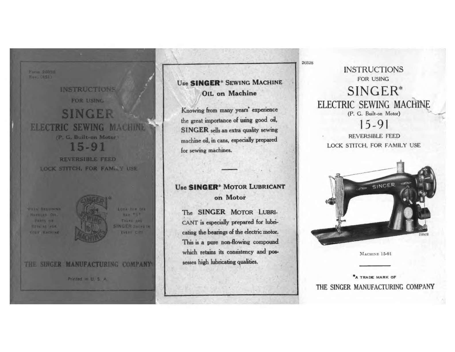
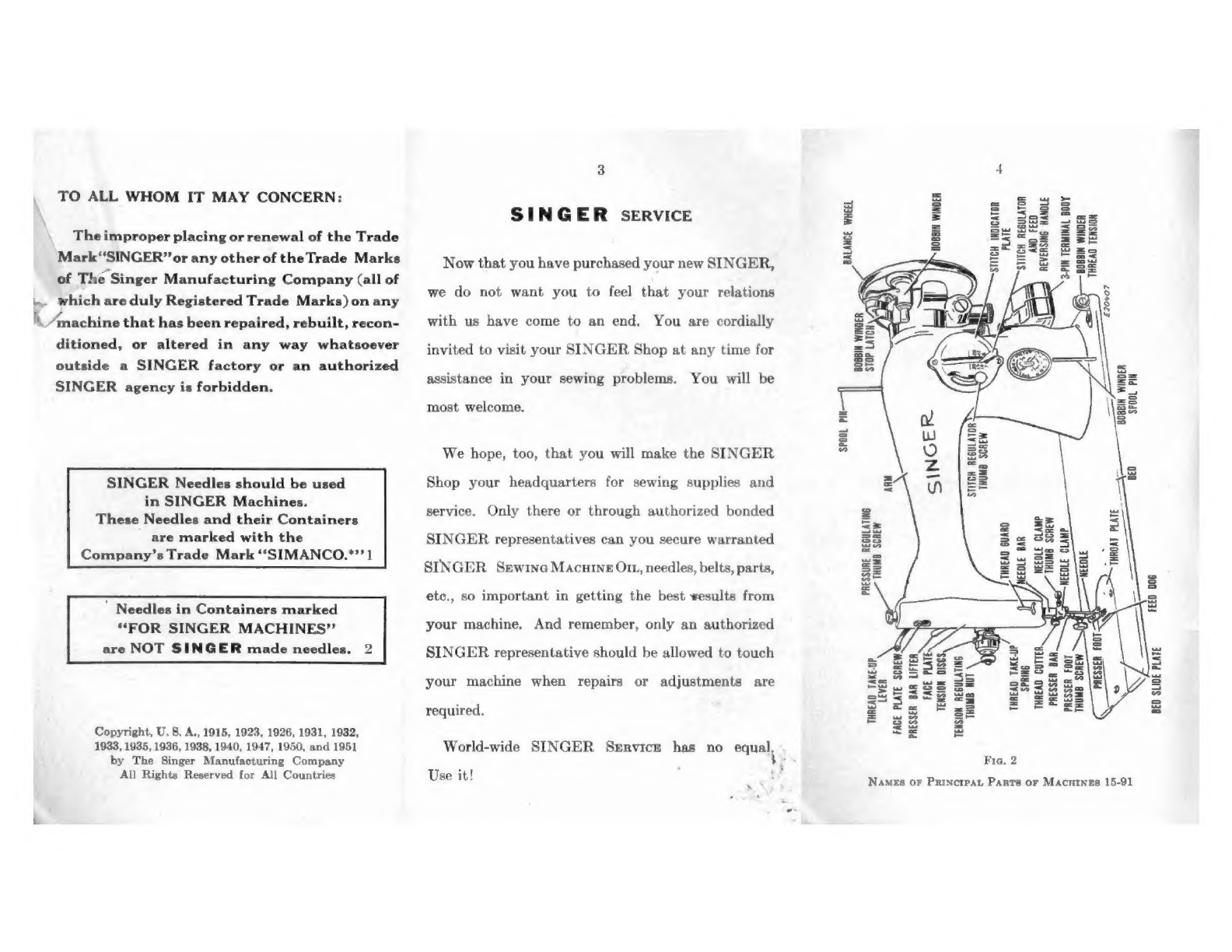
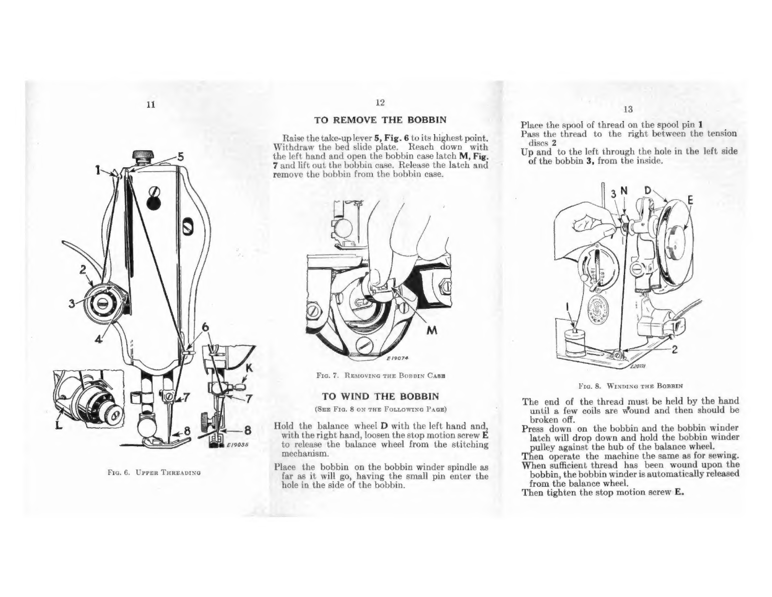
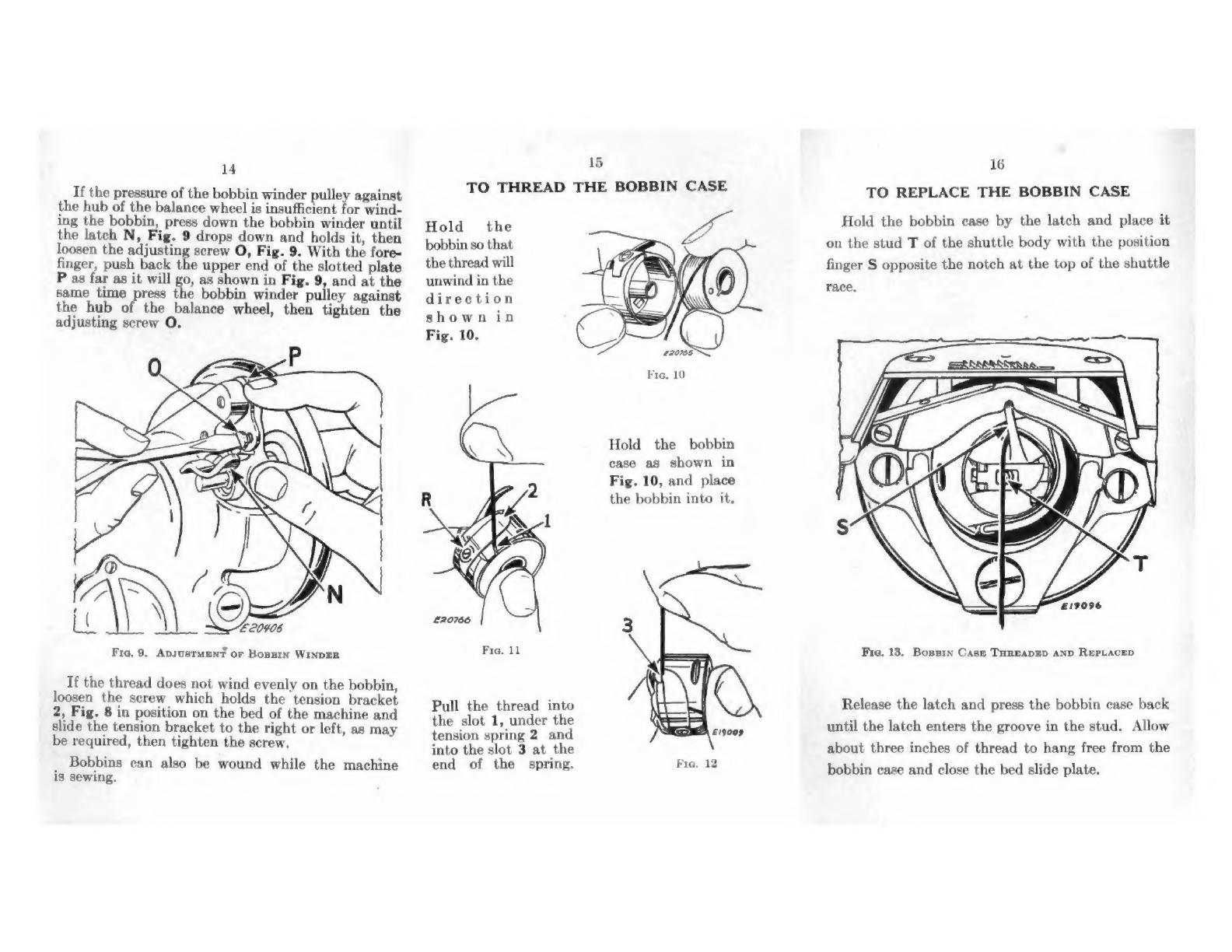
Singer 15-91 Installation and operation manual

20328
INSTRUCTIONS
Use
SINGER*
SEWING
MACHINE
FOR
USING
/OIL
on
Machine
S
]
N
G
E
R*
4
ELECTRIC
SEWING
MACHINE
Hiastone
fom
ee
oa
ite
(P.
G.
Built-on
Motor)
—_—
the
great
importance
of
using
good
oil,
|
:
9
|
‘
SINGER
sells
an
extra
quality
sewing
i
machine
oil,
in
cans,
especially
prepared
REVERSIBLE
FEED
?
:
LOCK
STITCH,
FOR
FAMILY
USE
for
sewing
machines.
Use
SINGER*
MoToR
LUBRICANT
on
Motor
The
SINGER
Motor
LUBRI-
CANT
is
especially
prepared
for
lubri-
cating
the
bearings
of
the
electric
motor.
This
is
a
pure
non-flowing
compound
which
retains
its
consistency
and
pos-
sesses
high
lubricating
qualities.
MacuineE
15-91
*A
TRADE
MARK
OF
THE
SINGER
MANUFACTURING
COMPANY

TO
ALL
WHOM
IT
MAY
CONCERN:
Theimproper
placing
or
renewal
of
the
Trade
Mark“‘SINGER”
or
any
other
of
the
Trade
Marks
of
The
Singer
Manufacturing
Company
(all
of
4
which
are
duly
Registered
Trade
Marks)
on
any
‘\
Amachine
that
has
been
repaired,
rebuilt,
recon-
ditioned,
or
altered
in
any
way
whatsoever
outside
a
SINGER
factory
or
an
authorized
SINGER
agency
is
forbidden.
SINGER
Needles
should
be
used
in
SINGER
Machines.
These
Needles
and
their
Containers
are
marked
with
the
Company’s
Trade
Mark
‘‘SIMANCO.*’’
1
’
Needles
in
Containers
marked
“FOR
SINGER
MACHINES”
are
NOT
SINGER
made
needles.
2
Copyright,
U.S.
A.,
1915,
1923,
1926,
1931, 1932,
1933,
1935,
1936,
1938,
1940, 1947, 1950,
and
1951
by
The
Singer
Manufacturing
Company
All
Rights
Reserved
for
All
Countries
SINGER
SERVICE
Now
that
you
have
purchased
your
new
SINGER,
we
do
not
want
you
to
feel
that
your
relations
with
us
have
come
to
an
end.
You
are
cordially
invited
to
visit
your
SINGER
Shop
at
any
time
for
assistance
in
your
sewing
problems.
You
will
be
most
welcome.
We
hope,
too,
that
you
will
make
the
SINGER
Shop
your
headquarters
for
sewing
supplies
and
service.
Only
there
or
through
authorized
bonded
SINGER
representatives
can
you
secure
warranted
SINGER
Srewrne
Macutne
Om,
needles,
belts,
parts,
etc.,
so
important
in
getting
the
best
¥esults
from
your
machine.
And
remember,
only
an
authorized
SINGER
representative
should
be
allowed
to
touch
your
machine
when
repairs
or
adjustments
are
required.
World-wide
SINGER
Service
has
no
equal,
Use
it!
»
=
Ss
Ss
Ss
=
=
=
Ss
Ss
s
=
AND
FEED
REVERSING
HANOLE
3-PIN
TERMINAL
BODY
PLATE
STITCH
REGULATOR
‘STITCH
INDICATOR
BOBBIN
WINDER
THREAD
TENSION
£20407
BOBBIN
WINDER
SPOOL
PIN
THUMB
SCREW
BED
THUMB.
SCREW
THROAT
PLATE
—NEEDLE
CLAMP
papa
FEED
006
THREAD
GUARD
NEEDLE
CLAMP
PRESSURE
REGULATING
THUMB
SCREW
a
\
TENSION
DISCS,
TE.
TENSION
REGULATING
LEVER
FACE
PLATE
SCREW.
FACE
PLA
PRESSER
BAR
LIFTER
SPRING
THREAD
CUTTER,
PRESSER
BAR
PRESSER
FOOT
THUMB
SCREW
BED
SLIDE
PLATE
THREAD
TAKE-UP
THUMB
NUT
Fra,
2
Names
or
Principat
Parts
or
Macutnes
15-91

0
DESCRIPTION
This
SINGER
family
sewing
machine
will
give
you
practically
life-time
service.
It
is
intended
for
operation
by
electricity,
having
an
electric
motor
built’
on
the
back
of
its
arm,
The
motor
drives
the
machine
through
spiral
gears.
It
is
also
equipped
with
an
electric
SINGER-
LIGHT*.
The
machine
has
an
oscillating
shuttle
on
a
hori-
zontal
axis
and
makes
the
lock
stitch.
It
has
reverse
feeding
mechanism
which
enables
you
to
sew
either
in
a
forward
or
backward
direction,
making
it
easy
to
back
tack
and
to
fasten
the
ends
of
seams.
In
addition
to
plain
sewing,
a
great
variety
of
pleasing
effects
such
as
hemming,
binding,
edge
stitching,
shirring,
ruffling,
etc.,
can
be
produced
with
the
aid
of
the
attachments
furnished
with
the
machine.
These
attachments
and
other
popular
SINGER
Fashion
Aids
will
enable
you
to
obtain
the
much
desired
tailored
appearance
of
professionally-
made
garments
and
to
add
new
fashion
touches
or
finishes
demanded
by
swiftly
changing
styles
at
a
fraction
of
the
cost
of
ready-made
garments.
READ
THIS
BOOK
CAREFULLY
TO
GET
THE
UTMOST
SERVICE
FROM
YOUR
SEWING
MACHINE
6
ELECTRICAL
INFORMATION
Motor
The
SINGER
electric
motor,
located
at
the
back
of
the
machine,
is
regularly
furnished
for
operation
on
a
direct
current
of
110-120
volts
or
on
alternating
current
of
110-120
volts,
25
to
75
cycles.
Special
motors
can
be
furnished
for
direct
or
alternating
current
for
any
voltage
between
50
and
250,
and
for
32
volts
direct
current.
To
Connect
Machine
to
Electric
Service
Line
Before
connecting
the
machine
to
the
electric
ser-
vice
line,
be
sure
that
the
voltage
and
the
number
of
cycles
stamped
on
the
motor
nameplate
are
with-
in
the
range
marked
on
the
electric
meter
installed
by
the
electric
power
company.
Push
the
terminal
plug
at
one
end
of
the
electric
cord
on
the
three-pin
terminal
block
(see Fig.
2,
page
4)
at
the
right
of
the
machine
and
connect
the
plug
at
the
other
end
of
the
cord
to
an
electric
outlet.
CAUTION
When
you
have
finished
your
sewing,
always
disconnect
the
plug
from
the
electric
outlet.
_
SINGERLIGHT
The
SINGERLIGHT
is
turned
“on”
or
“off”
by
the
switch
A,
Fig.
3.
To
Remove
the
Bulb
Fie.
3.
RepLactne
tHE
BuLB
Grasp
the
SINGERLIGHT
socket
so
that
the
thumb
extends
over
the
switch
A.
Press
the
shade
with
the
thumb
at
B
to
release
the
shade
from
the
two
catches
and
slide
it
half-
way
out
of
the
shade
holder
D.
Do
Not
Attempt
to
Unscrew
the
Bulb.
It
is
of
the
bayonet
and
socket
type
and
does
not
unscrew.
Press
the
Bulb
Into
the
Socket
and
at
the
same
time
turn
the
bulb
over
from
the
machine
as
far
as
it
will
go,
then
withdraw
the
bulb.
To
Replace
the
Bulb
Hold
the
socket
with
one
hand
and
at
the
same
time
with
the
other
hand
press
the
new
bulb
into
the
socket
and
turn
it
over
toward
the
machine
until
the
bulb
pin
C,
Fig.
3
enters
the
notch
in
the
socket.
_
Return
the
shade
to
its
normal
position,
as
shown
in
Fig.
3.

8
TO
OPERATE
THE
MACHINE
Raise
the
presser
foot
B
by
means
of
the
presser
bar
lifter
C
to
prevent
injury
to
the
foot
B
and
feed
A.
lezowo__
Fie.
4.
Front
View
or
rae
Macuine
Place
a
piece
of
cloth
under
the
presser
foot
and
let
the
foot
down
upon
it.
Turn
on
the
electric
current
and,
if
the
combina-
tion
knee
and
foot
controller
is
installed
as
a
knee
controller,
press
the
controller
to
the
right,
or,
if
the
controler
is
placed
on
the
floor
to
be
used
as
a
foot
controller,
press
down
on
the
pedal
of
the
controller.
As
the
pressure
on
the
controller
is
increased,
the
speed
of
the
machine
is
increased,
the
speed
being
controlled
entirely
by
the
amount
of
pressure
on
the
controller.
Operate
the
machine
in
this
way,
without
being
threaded,
until
you
have
become
accustomed
to
guiding
the
material
and
operating
the
controller.
9
NEEDLES
AND
THREADS
For
perfect
stitching,
the
thread
should
be
selected
according
to
the
fabric
to
be
stitched
and
the
needle
must
be
the
correct
size
for
the
thread
which
must
pass
freely
through
the
eye
of
the
needle.
CHART
SHOWING
THE
RELATIONSHIP
OF
TYPES
OF
FABRICS,
THREAD
AND
NEEDLE
SIZES
AND
MACHINE
STITCHES
TO
THE
INCH
|
MACHINE
TYPES
OF
THREAD NEEDLE
STITCHES
FABRICS
SIZES
SIZES
PER
INCH
Filmy
materials
comparable
100
Cotton
to
Net,
Marquisette,
Or-
OO
and
OOO
9
INSIDE)
TOP
SEAMS
STITCHING
gandie,
Ninon,
Silk
|
[20:1
se
Sheer
materials
comparable}
to
Lawn,
Dimity,
Voile,
80
to
100
11
16
20
Batiste, Chiffon,
Rayon,
Cotton
Sheer,
Rayon
Crepe.
O
Silk
Lightweight
muterials
com-|
60
io
80
i
parable
to
Gingham,
Cham-
Cotton
14
12
18
ray,
Sheer
Wool
Crepe,
A
and
B
Silk
Taffeta.
Medium
lightweight
mater-)
1
ials
comparable
to
Poplin,
Pique,
Percale,
Cretonne,|
50
to
70
Chintz,
Faille,
Bengaline,
Cotton
14
12
16
Wool
Flannel,
Wool
Crepe,,
B
Silk
|
Wool
Jersey.
|
|
Medium
heavy
materials)
.
comparable
to
Crash,
Gab-|
40
to
50
|
ardine,
Rep,
Corduroy,
Cotton
16 19 12
Velveteen.
C
Silk
Heavy
materials
compar-
30to40Cotton
18
Tay
able
to
Sailcloth,
Denim,|24to30Cotton
19
8
10
Ticking.
D
Silk
18
or
19
40
to
60
Linen
Very
heavy
materials
com
|20to24Cotton
21
6
8
parable
to
overcoating.
E
Silk
|
9
:
Mercerized
Plastic
materials.
Cotton
11
10
12
When
ordering
needles,
always
specify
“Class
and
Variety
15x1”’and
state
the
size
and
quantity
required.
10
TO
SET
THE
NEEDLE
Select
the
cor-
rect
needle
ac-
cording
to
the
K
table
on
page
9.
Be
sure
that
the
needle
is
not
blunt
or
bent.
Raise
the
needle
bar
to
its
highest
osition
and
oosen
the
thumb
screw
K
in
the
needle
clamp.
Push
the
needle
with
its
flat
side
to
the
left
up
into
the
needle
clamp
as
far
as
it
will
go,
then
tighten
the
thumb
screw.
UPPER
THREADING
(Sex
Fie.
6
on
THE
Fotuowrna
Pace)
Raise
the
take-up
lever
5
to
its
highest
point.
Place
the
spool
of
thread
on
spool
pin
at
top
of
machine
Pass
the
thread
through
the
thread
guide
1
Down,
under
and
from
back
to
front
between
the
tension
dises
2
(the
thread
guard
L
guiding
the
thread
between
the
dises)
:
Hold
the
spool
tightly
and
pull
the
thread
against
the
take-up
spring
4
until
it
enters
the
retain-
ing
fork
3
Pass
the
thread
from
back
to
front
through
the
hole
5
in
the
take-up
lever
Down
through
the
guide
6
on
the
face
plate
Into
the
guide
7
on
the
needle
clamp
From
right
to
left
through
the
eye
8
of
the
needle.
Draw
about
two
inches
of
thread
through
the
eye
of
the
needle
with
which
to
commence
sewing.
19010
i
Fra,
5,
Serrina
rue
NEEDLE

ll
Fie,
6.
Upper
THREADING
<—8
&/9035
12
TO
REMOVE
THE
BOBBIN
Raise
the
take-up
lever
5,
Fig.
6
to
its
highest
point.
Withdraw
the
bed
slide
plate.
Reach
down
with
the
left
hand
and
open
the
bobbin
case
latch
M,
Fig.
7
and
lift
out
the
bobbin
case.
Release
the
latch
and
remove
the
bobbin
from
the
bobbin
case.
£19074
Fie.
7.
Removing
tHE
Bonstn
Case
TO
WIND
THE
BOBBIN
(Sue
Fic.
8
on
tHE
Fottow1nae
PAGE)
Hold
the
balance
wheel
D
with
the
left
hand
and,
with
the
right
hand,
loosen
the
stop
motion
screw
E
to
release
the
balance
wheel
from
the
stitching
mechanism.
Place
the
bobbin
on
the
bobbin winder
spindle
as
far
as
it
will
go,
having
the
small
pin
enter
the
hole
in
the
side
of
the
bobbin.
13
Place
the
spool
of
thread
on
the
spool
pin
1
Pass
the
thread
to
the
right
between
the
tension
dises
2
Up
and
to
the
left
through
the
hole
in
the
left
side
of
the
bobbin
3,
from
the
inside.
Fie.
8.
Wrxpine
THE
BosBin
The
end
of
the
thread
must
be
held
by
the
hand
until
a
few
coils
are
Wound
and
then
should
be
broken
off,
Press
down
on
the
bobbin
and
the
bobbin
winder
latch
will
drop
down
and
hold
the
bobbin
winder
pulley
against
the
hub
of
the
balance
wheel.
Then
operate
the
machine
the
same
as
for
sewing.
When
sufficient
thread
has
been
wound
upon
the
bobbin,
the
bobbin
winder
is
automatically
released
from
the
balance
wheel.
Then
tighten
the
stop
motion
screw
E,

14
If
the
pressure
of
the
bobbin
winder
pulley
against
the
hub
of
the
balance
wheel
is
insufficient
for
wind-
ing
the
bobbin,
press
down
the
bobbin
winder
until
the
latch
N,
Fig.
9
drops
down
and
holds
it,
then
loosen
the
adjusting
screw
O,
Fig.
9.
With
the
fore-
finger,
push
back
the
upper
end
of
the
slotted
plate
P
as
far
as
it
will
go,
as
shown
in
Fig.
9,
and
at
the
same
time
press
the
bobbin
winder
pulley
against
the
hub
of
the
balance
wheel,
then
tighten
the
adjusting
screw
O.
Fie.
9.
ApsustMENT
or
Bopsrn
WINDER
If
the
thread
does
not
wind
evenly
on
the
bobbin,
loosen
the
screw
which
holds
the
tension
bracket
2,
Fig.
8
in
position
on
the
bed
of
the
machine
and
slide
the
tension
bracket
to
the
right
or
left,
as
may
be
required,
then
tighten
the
screw.
Bobbins
ean
also
be
wound
while
the
machine
is
sewing.
15
16
TO
THREAD
THE
BOBBIN
CASE
TO
REPLACE
THE
BOBBIN
CASE
Hold
the
bobbin
case
by
the
latch
and
place
it
ld
the
re
need
on
the
stud
T
of
the
shuttle
body
with
the
position
the
thread
will
finger
S
opposite
the
notch
at
the
top
of
the
shuttle
unwind
in
the
direction
shown
in
Fig.
10,
race,
bobbin
Hold
the
case
as
shown
in
Fig.
10,
and
place
the
bobbin
into
it.
Fie.
13.
Bossrn
Case
THREADED
AND
RepLaceD
Release
the
latch
and
press
the
bobbin
case
back
until
the
latch
enters
the
groove
in
the
stud.
Allow
Pull
the
thread
into
the
slot
1,
under
the
ion
spri
]
£19009
jefe
the
not
4
f
ne
about
three
inches
of
thread
to
hang
free
from
the
end
of
the
spring.
Brats
bobbin
case
and
close
the
bed
slide
plate.

17
TO
PREPARE
FOR
SEWING
Hold
the
end
of
the
needle
thread
with
the
left
hand
and
turn
the
balance
wheel
over
toward
you
until
the
needle
goes
down
and
up
again
and
the
thread
take-up
lever
5,
Fig.
16
is
at
its
highest
point.
Pull
up
the
needle
thread
and
Fra,
14
bobbin
thread
will
come
é 5
Drawine
Up
Tae
Bonpin
with
it,
as
shown
in
Temas
Fig.
14.
Lay
both
threads
back
under
the
presser
foot
diag-
onally
across
the
feed,
as
shown
in
Fig.
15,
to
the
right
or
left,
depending
upon
which
side
of
the
needle
the
material
is
to
be
located,
so
that
when
the
presser
foot
is
lowered,
the
threads
will
be
firmly
held
between
the
feed
and
the
presser
foot
Fia.
15
THREADS
IN
PosITION
TO
Commence
Sewina
18
TO
COMMENCE
SEWING
Be
sure
to
have
the
thread
take-up
lever
*
5
at
its
highest
point.
Place
the
material
beneath
the
presser
foot
B,
lower
the
foot
by
means
of
the
presser
bar
lifter
C
and
com-
mence
to
sew,
turning
the
balance
wheel
over
toward
you.
Never
pull
the
ma-
terial
along
when
stitching.
This
is
liable
to
bend
the
needle.
Guide
the
material
only.
Never
operate
the
machine
without
cloth;
under
presser
foot.
Fre.
16
The
slide
over
the
bobbin
case
should
be
kept
closed
when
the
machine
is
in
operation,
The
balance
wheel
must
always
turn
over
toward
the
operator.
19
TO
TURN
A
CORNER
Stop
the
machine
when
the
needle
is
commencing
its
upward
stroke.
Raise
the
presser
foot
and
turn
the
work
as
desired,
using
the
needle
as
a
pivot,
then
lower
the
presser
foot.
BASTING
Adjust
the
stitch
regulator
X,
Fig.
17
to
make
the
longest
stitch
and
loosen
the
needle
thread
ten-
sion
A,
Fig.
21,
so
that
the
stitches
may
be
easily
removed,
Machine
basting
is
firmer,
more
even
and
much
quicker
than
hand
basting.
TO
SEW
FLANNEL
OR
BIAS
SEAMS
Use
a
short
stitch
and
as
light
tension
as
possible
on
the
needle
thread
so as
to
leave
the
thread
loose
enough
in
the
seam
to
allow
the
material
to
stretch
if
necessary.
TO
REMOVE
THE
WORK
Stop
the
machine
with
the
thread
take-up
lever
5,
Fig.
16
at
its
highest
position,
Raise
the
presser
foot,
draw
the
fabric
back
and
to
the
left,
and
sever
the
threads
on
the
thread
cutter
U,
Fig.
16.
Place
the
ends
of
the
threads
under
the
presser
foot,
as
shown
in
Fig.
15.

20
TO
REGULATE
THE
LENGTH
OF
STITCH
The
machine
is
adjustable
to
make
from
6
to
30
stitches
per
inch,
as
indicated
by
the
numerals
on
the
stitch
indicator
plate
W.
Ww
£19039
Fig.
17.
SHowrne
Lever
ror
Reverstne
Direction
or
Freep
anp
Reeuuatine
Leneru
or
Strrcw
The
number
of
stitches
to
the
inch
that
the
ma-
chine
is
set
to
make
is
indicated
by
the
number
which
is
in
line
with
the
upper
side
of
the
stitch
regulating
lever
X.
To
change
the
length
of
stitch,
loosen
the
thumb
screw
Y
and
move
it
to
the
bottom
of
the
slot.
Then
move
the
stitch
regulating
lever
X
until
its
upper
side
is
in
line
with
the
number
of
the
desired
length
of
stitch.
Now
move
the
thumb
screw
Y
until
the
stitch
regulating
plate
(inside)
touches
the
lever
X,
then
tighten
the
thumb
screw
Y.
The
machine
will
now
make
the
indicated
number
of
stitches
to
the
inch
in
either
a
forward
or
reverse
direction,
depending
on
whether
the
lever
X
is
at
its
lowest
or
highest
position.
21
TO
REGULATE
THE
DIRECTION
OF
FEED
To
feed
the
material
from
you,
push
down
the
stitch
regulating
lever
X,
Fig.
17
as
far
as
it
will
go.
To
feed
the
material
toward
you,
raise
the
stitch
regulating
lever
X
as
high
as
it
will
go.
The
direction
of
feeding
can
be
reversed
at
any
point
of
a
seam
without
removing
the
work
from
the
machine,
:
The
reverse
feed
makes
it
easy
to
do
‘“‘back
tack-
ing”
and
to
fasten
the
ends
of
seams.
TO
REGULATE
PRESSURE
ON
PRESSER
FOOT
For
ordinary
sewing,
the
pressure
of
the
presser
foot
on
the
material
seldom
requires
changing.
Heavy
materials
require
more
pressure
than
light
weight
materials,
The
pressure
should
be
only
heavy
enough
to
prevent
the
material
from
rising
with
the
needle
and
to
enable
the
feed
to
move
the
work
along
evenly.
To
increase
the
pressure,
turn
the
thumb
screw
V,
Fig.
16
clockwise
or
downward.
To
lighten
the
pressure,
turn
the
thumb
screw
so
that
it
screws
upward.
SINGER
Needles
should
be
used
in
SINGER
Machines.
These
Needles
and
their
Containers
are
marked
with
the
Company’s
Trade
Mark
‘“‘SIMANCO.*’’
|
Needles
in
Containers
marked
“FOR
SINGER
MACHINES”
are
NOT
SINGER
made
Needles.
2
22
THREAD
TENSIONS
For
ordinary
stitching,
the
needle
and
bobbin
threads
should
be
locked
in
the
center
of
the
thick-
ness
of
the
material,
thus:
758
Fie.
18.
Perrecr
StrrcHine
Tf
the
tension
on
the
needle
thread
is
too
tight,
or
if
that
on
the
bobbin
thread
is
too
loose,
the
needle
thread
will
lie
straight
along
the
upper
surface
of
the
material,
thus:
Fie.
19.
Tiagur
Nerpie
Tureap
Tension
If
the
tension
on
the
bobbin
thread
is
too
tight,
or
if
that
on
the
needle
thread
is
too
loose,
the
bobbin
thread
will
lie
straight
along
the
underside
of
the
material,
thus:
Ena
Fra.
20.
Loose
Negepie
Tareay
Pension
TO
REGULATE
THE
NEEDLE
THREAD
TENSION
The
tension
on
the
needle
thread
can
be
regulated
only
when
the
presser
foot
is
down.
The
numerals
‘‘0
to
9”’
on
the
dial
C,
Fig.
21
indicate
the
dif-
ferent
degrees
of
ten-
sion
that
can
be
obtained.
The
num-
bers
do
not
denote
the
size
of
thread
or
ounces
of
tension.
Fria,
21,
Neepie
THREAD
TENSION

23
When
the
tension
has
been
correctly
set
for
aver-
age
sewing,
note
the
number
at
the
indicator
line
Q,
so
that
the
tension
may
be
reset
should
it
be
altered
for
special
work
or
change
in
size
of
thread.
Toincrease
the
tension,
turn
the
thumb
screw
A
gradually
to
the
right
(clockwise)
until
the
required
tension
is
obtained.
Each
higher
number
denotes
increased
tension.
To
decrease
the
tension,
turn
the
thumb
screw
A
gradually
to
the
left
(counter-clockwise)
until
the
required
tension
is
obtained.
Each
lower
number
denotes
less
tension.
TO
REGULATE
THE
BOBBIN
THREAD
TENSION
The
tension
on
the
bobbin
thread
is
regulated
by
the
screw
R,
Fig.
11
in
the
tension
spring
on
the
outside
of
the
bobbin
case.
To
increase
the
tension,
turn
the
screw
R
over
to
the
right.
To
decrease
the
tension,
turn
this
screw
over
to
the
left.
When
the
tension
on
the
bobbin
thread
has
been
once
properly
adjusted,
it
is
seldom
necessary
to
change
it,
as
a
correct
stitch
can
usually
be
obtained
by
varying
the
tension
on
the
needle
thread.
24
TO
DISASSEMBLE
THE
NEEDLE
THREAD
TENSION
NOTE:
The
needle
thread
tension,
Figs.
21
to
23
inclusive,
is
correctly
adjusted
at
the
fac-
tory
to
produce
the
complete
range
of
tensions
with
one
revolution
of
the
thumb
nut
A.
There
should
be
no
necessity
for
removing
or
taking
this
tension
apart.
However,
if
for
any
reason,
it
becomes
necessary
to
remove
the
tension,
proceed
as
follows:
Turn
the
thumb
nut
A,
Fig.
22
away
from
you
(toward
the
left)
until
it
stops
at
“0”
on
the
num-
Fre.
22.
Neepie
Tureap
Tension
DIsass—EMBLED
bered
dial
C.
Press
in
the
dial
to
disengage
the
pin
B
in
the
thumb
nut
and
remove
the
thumb
nut,
dial,
stop
washer
D,
tension
spring
F,
indicator
G,
the
two
tension
dises
H,
thread
guard
plate
L,
and
the
tension
releasing
pin
J,
as
shown
in
Fig.
22.
To
remove
the
pin
J
from
the
stud
N,
take
off
the
face
plate
and
tilt
it
so
that
the
pin
will
drop
out.
25
TO
REASSEMBLE
THE
NEEDLE
THREAD
TENSION
Replace
the
face
plate,
insert
the
tension
releasing
pin
in
the
stud,
place
the
thread
guard
plate
on
the
Vig.
23.
REassEMBLING
AND
REPLACING
THE
TENSION
stud,
being
sure
that
the
lug
M,
Fig.
22
engages
the
short
recess
P
to
prevent
the
plate
from
turn-
ing
on
the
stud.
Next,
replace
the
two
tension
discs
H
on
the
stud,
having
the
flat
thread-bearing
sides
of
the
dises
together.
Replace
the
indicator
G
with
the
large
open
side
facing
end
of
stud
so
that
the
plus
and
minus
signs
will
be
readily
seen
from
a
sewing
position
as
shown
in
Fig.
23.
Insert
the
ten-
sion
spring
F
in
the
indicator
so
that
the
first
half
turn
F2
of
this
spring
will
straddle
the
lower
half
of
the
tension
stud.
Guide
the
stop
washer
D
onto
the
stud
so
that
the
extension
S
will
be
above
the
ten-
sion
stud
as
shown
in
Fig.
23.
NOTE:
If
the
spring
and
stop
washer
are
in
cor-
rect
position,
the
extension
S
will
clear
the
first
half-
coil
of
the
spring,
$
*
as
shown
in
Fig.
24.
Next
place
the
numbered
dial
on
the
stud
so
that
the
numeral
2
is
oppo-
£19048
Fre.
24

26
site
the
stop
washer
extension
S,
then
push
the
dial
to
compress
the
spring
so
that
the
thumb
nut
can
be
turned
onto
the
stud,
carefully
guiding
the
pin
in
the
thumb
nut
into
one
of
the
holes
in
the
numbered
dial.
Lower
the
presser
bar
and
turn
the
thumb
nut
A
to
the
left
until
it
stops
at
“0.”?
Thread
the
tension
and
pull
the
thread
through
the
tension
dises
to
test
the
amount
of
tension
at
the
‘“O”’
position.
At
this
point
there
should
be
a
barely
perceptible
pull
on
the
thread
to
indicate
that
there
is
a
minimum
tension
which
gradually
increases
with
the
turn
of
the
thumb
nut
to
the
right,
providing
a
full
range
of
tensions
from
light
to
heavy
within
one
revolution
of
the
thumb
nut.
If
the
pull
is
too
strong
for
a
minimum
tension,
press
in
the
numbered
dial
to
disengage
the
pin
in
the
thumb
nut
from
the
dial
and
reset
the
pin
in
one
of
the
holes
to
the
left
of
the
previous
setting.
This
resetting
of
the
pin
will
produce
less
tension
at
zero.
On
the
other
hand,
should
there
be
insufficient
tension
at
zero,
press
in
the
dial
and
reset
the
pin
in
one
of
the
holes
to
the
right
of
the
previous
set-
ting.
Repeat
this
process
until
the
desired
minimum
tension
is
obtained.
If
Correct
Stitching
is
Not
Obtained:
If
the
bobbin
thread
tension
has
been
disturbed,
or
a
correct
stitch
cannot
be
obtained
without
a
very
heavy
or
very
light
needle
thread
tension,
then
the
following
procedure
is
recommended:
Using
No.
50
thread
in
the
needle
and
on
the
bob-
bin,
adjust
the
needle
thread
tension
as
instructed
above.
Then
turn
the
tension
thumb
nut
to‘3”
and,
with
two
thicknesses
of
thin
material
in
the
machine,
adjust
the
bobbin
thread
tension,
as
instructed
on
page
23,
until
the
stitch
is
correctly
locked
in
the
material
as
shown
in
Fig.
18.
A
wide
range
of
materials
and
threads
can
now
be
accommodated
without
further
adjustment
of
the
bobbin
thread
tension.
27 28
Loosen
the
thumb
screw
in
the
round
cover
plate
at
the
back
of
the
machine,
turn
the
plate
upward
and
fasten
by
tightening
the
screw.
Turn
the
bal-
ance
wheel
over
toward
you
until
the
connecting
TO
OIL
THE
MACHINE
If
the
machine
is
used
continuously,
it
should
be
oiled
daily.
If
moderately
used,
an
occasional
oiling
is
sufficient.
Fie.
25.
Front
View,
Suowrne
Ornine Points
Apply
one
drop
of
oil
at
each
of
the
places
indicated
by
the
unlettered
arrows
in
Figs.
25,
27
and
28.
Fra.
26.
Omine
Ports
ar
THE
Back
or
THE
MACHINE
rod
Z,
Fig.
26
is
at
its
highest
position.
Then
apply
a
few
drops
of
oil
through
the
hole
in
the
top
of
the
machine
to
the
wick
which
is
retained
in
the
cap
of
the
connecting
rod,
as
shown
in
Fig.
26.
Also
oil
the
other
moving
parts
inside,
turn
the
cover
plate
down
and
fasten
it
as
before.
Draw
to
the
left
the
bed
slide
plate,
and
after
removing
the
lint
and
dust
which
may
have
accumu-
lated
(see
instructions
on
pages
31
and
32),
apply
oil
to
the
shuttle
race
A,
Fig.
30.
The
slide
should
then
be
closed

29
Loosen
the
screw
A2,
Fig.
27
near
the
upper
end
of
the
face
plate,
raise
the
plate
and
slip
it
off
over
the
head
of
the
screw.
Apply
one
drop
of
oil
at
each
of
the
places
indicated
by
the
unlettered
arrows
in
Fig.
27,
then
replace
the
face
plate
and
fasten
it
as
before,
To
reach
the
parts
under-
neath
the
bed
of
the
machine,
turn
the
machine
back
on
its
hinges.
Apply
one
drop
of
oil
at
each
of
the
places
indicat-
ed
by
the
unlettered
arrows
in
Fig.
28.
Fic.
27.
Exp
View
Suow1ne
O1nine
Pornts
Fra.
28,
Ornrne
Pornts
ry
Base
or
MACHINE
30
TO
LUBRICATE
THE
MOTOR
NEVER
USE
OIL
OR
ORDINARY
GREASE
FOR
LUBRICATING
THE
MOTOR
as
they
are
harmful
for
this
purpose.
USE
ONLY
SINGER
Moror
Lusricant,
a
tube
of
which
is
supplied
with
the
machine.
It
is
the
only
lubricant
which
will
positively
lubricate
the
motor.
When
the
machine
is
shipped
from
the
factory,
the
two
motor
grease
cups
A,
Fig.
29
are
filled
with
sufficient
SINGER
Moror
Lusricanr
for
approx-
imately
one
year’s
use.
Refill
these
grease
cups
at
least
once
a
year
thereafter.
Turn
the
machine
back
on
its
hinges
and
remove
the
two
thumb
screws
from
the
two
grease
cups
A
and
clean
out
the
interior
of
the
cups.
Then
insert
the
tip
of
the
motor
lubricant
tube
into
the
grease
cups
as
shown
in
Fig.
29,
and
while
holding
the
tube
firmly
against
the
-bottom
of
the
grease
cups,
squeeze
enough
grease
into
each
cup
to
fill
them.
Replace
and
tighten
the
thumb
screws.
31
£
Fie,
29,
Luskicatine
Toe
Motor
M
Machine
Working
Heavily
If
the
machine
runs
hard
after
standing
idle
for
some
time,
use
a
little
kerosene
in
the
oiling
places,
run
the
machine
rapidly,
then
wipe
clean
and
oil.
To
Clean
the
Stitch
Forming
Mechanism
After
considerable
use,
the
stitch
forming
mechan-
ism
in
the
bed
of
the
machine
may
become
clogged
with
lint
and
this
may
interfere
with
the
perfect
operation
of
the
machine.

32
Occasionally
remove
the
shuttle
from
the
machine,
as
instructed
below
and
remove
any
lint,
ete.,
which
has
accumulated
in
the
machine.
TO
REMOVE
THE
SHUTTLE
Draw
the
bed
slide
plate
to
the
left.
Turn
the
balance
wheel
over
toward
you
until
the
needle
is
£19029
Fre.
30.
SHowine
Position
or
SHurriy
ror
Removat
rrom
Macutne
at
its
highest
point
and
the
point
of
the
shuttle
is
at
the
position
shown
in
Fig.
30.
Remove
the
bobbin
case
and
bobbin.
Take
out
the
thumb
screw
D,
Fig.
30,
also
the
spring
C,
Fig.
30
and
the
shuttle
race
back
B,
Figs.
30
and
31.
The
shuttle
A,
Figs.
30
and
31
may
now
be
easily
removed
and
the
parts
cleaned.
33
TO
REPLACE
THE
SHUTTLE
See
that
the
needle
is
at
its
highest
point.
Replace
the
shuttle
with
its
point
A
in
the
position
shown
£/9033
Fie.
31,
SHurr.e
anp
Parts
Removep
rrom
MACHINE
in
Fig.
31,‘then
replace
the
other
parts
in
the
order
illustrated
in
Fig.
31.
Replace
and
tighten
the
thumb
screw
D.
Replace
the
bobbin
and
bobbin
case
and
close
the
bed
slide
plate.
34
SEWING
SUGGESTIONS
Breaking
of
needles
might
be
caused
by:
(1)
Improper
size
of
needle
for
thread
and
material.
See
page
9.
(2)
Needle
bent.
(3)
Pulling
of
material
when
stitching.
(4)
Needle
striking
improperly
fastened
presser
foot
or
attachments.
(5)
Crossing
too
thick
seams
with
too
small
a
needle.
Breaking
of
needle
thread
might
be
caused
by:
(1)
A
knot
in
the
thread.
(2)
Improper
threading.
See
page
11.
(3)
Upper
tension
too
tight.
See
page
22.
(4)
Needle
set
incorrectly.
See
page
10.
(5)
Needle
blunt
or
bent.
(6)
Thread
too
coarse
for
needle..
See
page
9.
(7)
Roughened
hole
in
throat
plate.
(8)
Improper
arrangement
of
threads
to
commence
sewing.
See
page
17.
Breaking
of
bobbin
thread
might
be
caused
by:
(1)
Improper
threading
of
the
bobbin
case.
See
page
15.
(2)
Bobbin
thread
tension
too
tight.
See
page
23.
(3)
Bobbin
wound
unevenly.
Skipping
of
stitches
might
be
caused
by:
(1)
Improper
setting
of
needles.
See
page
10.
(2)
Needle
blunt
or
bent.
(3)
Needle
too
small
for
thread.
See
page
9.
(4)
Needle
rubbing
presser
foot.
Free
instruction
for
using
the
machine
is
gladly
given
at
any
SINGER
Shop.

35
DARNING
OR
EMBROIDERING
Turn
the
machine
back
on
its
hinges.
Unscrew
as
far
as
possible
the
thumb
screw
B,
Fig.
32
which
is
located
in
the
lower
end
of
the
slot
of
the
feed
Fie.
32,
ApsustMENT
ror
DaRNING
OR
EMBROIDERING
lifting
crank
A,
Fig.
32.
The
feed
is
thus
rendered
inoperative
and
will
not
interfere
with
the
free
movement
of
the
work.
Bring
the
machine
forward
into
place.
Move
the
stitch
regulating
lever
X,
Fig.
17
to
its
neutral
position
in
the
center
of
the
slot
at
the
front
of
the
machine.
Remove
the
presser
foot
and
let
down
the
presser
bar
lifter
C,
Fig.
16
to
restore
the
tension
on
the
needle
thread
which
is
released
when
the
lifter
is
raised.
Draw
up
the
bobbin
thread
as
instructed
on
page
17.
36
When
darning
flat
work,
it
is
advisable
to
use
embroidery
hoops
to
hold
the
work.
Place
the
work
in
the
machine,
having
the
un-
worn
part
near
the
hole
under
the
needle.
Com-
mence
the
darn-
ing
by
making
a
line
of
stitches
across
the
hole
a
little
longer
than
the
width
of
the
hole.
Continue
ma-
king
parallel
lines
of
stitches
across
the
hole,
moving
the
work
backward
and
forward
and
at
the
same
time
gradually
moving
the
work
side-
wise
until
the
hole
is
covered
with
lines
of
stitches
running
across
the
hole.
Then
commence
as
before
and
move
the
work
lengthwise
of
the
hole
until
the
stitches
across
the
hole
are
completely
coy-
ered
and
the
darn
is
finished,
Fie.
33,
Darntne
in
Process
Fre.
34.
Darntne
Frxiseep
37
When
you
have
finished
the
darning
or
embroidery,
raise
the
presser
bar
lifter
and
replace
the
presser
foot.
Turn
the
machine
back
on
its
hinges
and
move
the
thumb
screw
B,
Fig.
32
down
to
the
bottom
of
the
slot
of
the
feed
lifting
crank
A,
Fig.
32
and
make
sure
that
the
thumb
screw
is
firmly
tightened.
Bring
the
machine
forward
into
place,
return
the
stitch
regulating
lever
X,
Fig.
17
to
its
original
posi-
tion
and
the
machine
is
ready
for
regular
stitching.
Stockings
and
socks,
underwear,
etc.,
can
be
more
conveniently
darned
on
the
machine
with
the
SINGER
Darner
which
can
be
purchased
at
any
SINGER
Shop
or
from
any
SINGER
Salesman.
SINGER
Needles
should
be
used
in
SINGER
Machines.
These
Needles
and
their
Containers
are
marked
with
the
Company’s
Trade
Mark
‘‘SIMANCO.*”’
|
:
Needles
in
Containers
marked
“FOR
SINGER
MACHINES”
are
NOT
SINGER
made
Needles.
2

35
INSTRUCTIONS
FOR
USING
THE
ATTACHMENTS
THE
FOOT
HEMMER
The
foot
hemmer
may
be
used
for
hemming
the
edge
of
the
ma-
terial,
making
hemmed
and
felled
seams
and
for
hemming
and
sew-
ing
on
lace
in
one
operation
To
Attach
the
Foot
Hemmer
Raise
the
needle
to
its
highest
oud
point,
remove
the
presser
foot
and
attach
the
foot
hemmer
to
Fie.
35
the
presser
bar
in
place
of
the
Foor
Hemaer
presser
foot.
Pull
up
the
bobbin
thread
as
instructed
on
page
17.
To
Start
the
Hem
at
the
Edge
(1)
Fold
edge
of
material
twice,
about
1
inch
each
time,
for
a
distance
of
about
two
inches.
Crease
folds.
(2)
Lay
about
three
inches
of
needle
and
bobbin
threads
back
under
hemmer.
Place
creased
edge
of
material
under
hemmer
with
end
of
hem
di-
rectly
under
needle.
Lower
hemmer
and
tack
end
of
hem
with
two
machine
stitches.
39
(3)
Raise
hemmer.
Pull
threads
and
hem
slightly
from
you
with
left
hand,
then
while
holding
threads,
draw
material
toward
you
with
right
hand
into
seroll
of
hemmer
until
tacked
end
is
caught
in
hemmer,
as
shown
in
Fig.
36.
£20680
Fria.
36.
Srartine
Hem
at
Very
Env
or
Marertau
(4)
Lower
hemmer
and
commence
to
sew,
slightly
pulling
threads
back
while
sewing.
Keep
mouth
of
emmer
full
to
produce
a
smooth,
even
hem,
as
shown
in
Fig.
36A.
Fre.
36a.
Hemmine
Eper
or
MATERIAL
AND
Punting
Back
THreAps
Wu1Le
Sewine
40
To
Make
a
Hemmed
Seam
with
the
Foot
Hemmer
(1)
When
making
this
seam,
the
garment
must
first
be
fitted
and
the
edge
of
the
ma-
terial
trimmed,
allowing
for
about
14
inch
seam.
Insert
the
two
edges
of
the
material,
right
sides
together,
in
the
hemmer
in
the
same
manner
as
a
single
hem
as
shown
in
Fig.
37.
If
the
material
is
bulky,
place
the
edge
of
the
upper
piece
of
material
about
4%
inch
to
the
left
of
the
edge
of
the
under
piece.
Fie.
37
Maxine
A
Hemmep
Seam
(First
Oppration)
(2)
The
free
edge
of
the
hem-
med
seam
may
be
stitched
flat
to
the
garment,
if
desired.
To
do
this,
open
the
work
out
flat,
wrong
side
up,
then
insert’
the
hem
in
the
scroll
of
the
hemmer,
holding
the
edge
of
the
hem
in
position
while
it
is
being
stitched.
If
the
seam
is
stitched
flat
to
the
garment,
one
row
of
stitching
is
visible
on
the
right
side.
|€
180784
Fre.
38
Maxine
4
Hemmep
Seam
(Seconp
Operation)

41
42
43
‘o
Make
a
Felled
Seam
with
the
Reaiiten,
aod
Sewon
Lace
ADJUSTABLE
HEMMER
*oot
Hemmer
in
One
O
i i
peration
To
Make
Hems
from
3/16
to
15/16
Inch
Wide
(1)
Place
the
right
4
5
(1)
Attach
the
adjustable
hemmer
to
the
presser
bar
$s
elneat
dheteteantne
(1)
Start
the
hem
in
the
regular
way.
in
place
of
the
presser
foot.
a
gether,
having
the
edge
(2)
Hold
the
hem
in
position
with
the
needle.
(2)
Pullup
the
bobbin
thread,
asinstructed
on
pagel7.
2
of
the
upper
piece
about
I
¥
inch
to
the
left
of
the
edge
of
the
under
piece.
Stitch
the
two
pieces
to-
gether,
using
the
hemmer
as
a
presser
foot.
Guide
both
pieces
by
the
pro-
jecting
toe
of
the
hem-
mer,
asshown
in
Fig.
39.
t@.
39.
Maxine
A
Fettep
SEAM
(First
OPERATION)
Fre.
41,
(2)
Open
the
work
HEMMING
AND
SEWING
ON
Lace
Fie.
42,
Snowrne
How
ApsustasLe
Hemmer
1s
Usep
ror
Maxine
Hems
up
To
15/16
Inch
WIDE
out
flat,
wrong
side
up,
(3)
Raise
the
presser
bar
and
insert
the
edge
of
3)
Loosen
the
thumb
screw
on
the
hemmer
and
move
and
hem
the
free
edge
8
the
A
. A
;
.
s
lace
in
the
slot
of
the
hemmer
and
back
und
the
scale
until
the
pointer
registers
with
the
:
ander
number
of
the
desired
width
of
hem,
No.
1
indi-
cating
the
narrowest
hem
and
No.
8,
the
widest,
then
tighten
the
thumb
screw.
(4)
Place
the
cloth
in
the
hemmer
and
draw
it
back
wre
|
catching
the
edge
of
the
lace
with
the
needle.
7
ae
until
the
hem
is
formed,
as
shown
(5)
Draw
the
end
of
the
hem
back
under
the
needle,
of
the
seam,
stitching
it
the
hemmer.
flat
to
the
garment
as
(4)
Lower
the
presser
bar
and
commence
sewing,
shown
in
Fig.
40.
(5)
Guide
the
hem
with
the
right
hand
and
the
lace
Fre.
40.
Maxine
A
Fetiep
Seam
*
.
lower
th
esser
bar
and
nce
to
sew
with
the
lett
being-can
;
ower
the
presser
bar
and
commence
to
sew.
(Seconp
OPERATION)
-
g
careful
not
to
stretch
the
1
‘
(6)
Guide
sufficient
cloth
into
the
hemmer
to
turn
the
ace
as
it
enters
the
hemmer.
hem
properly.

44
To
Make
Hems
Wider
than
15/16
Inch
(1)
Loosen
the
thumb
screw
on
the
hemmer,
move
the
scale
to
the
right
as
far
as
it
will
go,
then
swing
it
toward
you,
as
shown
in
Fig.
43,
and
tighten
the
thumb
screw.
(2)
Fold
and
crease
the
desired
width
of
hem.
5a
Tie.
43,
Sxowrne
How
AvsusTaBLe
Hemmer
1s
UsED
ror
Maxine
Hems
Wiper
roan
15/16
Incu
(3)
Place
the
fold
under
the
extension
at
the
right
of
the
hemmer
and
the
edge
into
the
folder,
as
shown
in
Fig.
43.
(4)
Draw
the
end
of
the
hem
back
under
the
needle,
lower
the
presser
bar
and
commence
to
sew.
(5)
Guide
the
cloth
to
keep
the
hem
flat.
45
MULTI-SLOTTED
BINDER
This
multi-slotted
binder
will
apply
unfolded
bias
binding
+3
inch
in
widthand
commercial
folded
binding
in
sizes
1,
2,
3,
4
and
5
to
the
seams
or
to
the
edges
of
garments.
These
sizes
of
folded
binding
are
14,
#:,
34,
7
and
inch
in
width,
respectively,
and
are
fed
through
slots
of
corresponding
sizes
in
the
binder
scroll.
See
Fig.
44.
Binding
may
be
purchased
in
a
variety
of
materials
and
colors.
For
convenience
in
determining
the
correct
width
of
unfolded
binding
(43
inch),
this
measurement
is
marked
on
the
binder,
as
shown
in
Fig.
44.
The
two
upright
guide
pins
shown
in
Fig.
44
elim-
inate
meriual
goidine
of
the
binding.
ADJUSTING
LUG
SCROLL
FOR
UNFOLDED
BINDING
OUTSIDE
SLOTS
FOR
6"
DIFFERENT
3,
WIDTHS
OF
78
FOLDED
Ae"
BINDING
—
yu
CENTER
SLOT
y
OF
SCROLL
EDGE
GUIDE
GUIDE
PINS’
FOR
PIPING
ONLY
eens
Fia.
44.
Muuti-Storrep
Binper
160359
The
wide
range
of
bindings
that
can
be
applied
with
this
binder
makes
it
useful
for
a
large
variety
of
work.
It
will
be
found
particularly
advantageous
for
making
children’s
wear,
lingerie,
summer
dresses,
and
other
dainty
articles
which
call
for
the
nar-
rower
bindings.
46
As
two
different
widths
of
binding
of
contrasting
color
can
be
fed
through
the
binder
at
the
same
time,
attractive
binding
and
piping
effects
can
be
produced
in
one
operation.
To
Attach
the
Binder
Raise
the
needle
to
its
highest
position,
then
at-
tach
the
binder
to
the
presser
bar
in
place
of
the
presser
foot.
See
that
the
needle
enters
the
center
of
the
needle
hole.
To
Insert
the
Binding
In
the
Binder
Cut
all
binding
to
a
long
point
to
the
left,
as
shown
in
Fig.
45.
Folded
bias
binding
must
be
inserted
in
the
slot
or
slots
of
cor-
responding
sizes.
See
Fig.
48.
Unfolded
or
raw
edge
bias
binding
must
be
inserted
in
the
open
end
of
the
scroll.
See
Fig.
46.
After
inserting
the
pointed
end
of
the
binding
in
the
binder,
push
it
through
until
the
full
width
of
the
binding
is
under
the
needle.
Guide
the
binding
by
means
of
the
two
upright
pins,
as
shown
in
Figs.
46
and
48.

47
To
Insert
the
Garment
in
the
Binder
Place
the
edge
to
be
bound
as
far
to
the
right
as
it
will
go
in
the
center
slot
of
the
scroll
C2,
as
shown
in
Fig.
46,
and
draw
it
back
under
the
binder
foot.
Fig.
46.
Brnpine
wits
Unroipep
Binpina
Lower
the
binder
by
means
of
the
presser
foot
lifter,
and
commence
to
sew.
Keep
the
material
well
within
the
center
slot
of
the
scroll
so
that
the
edge
will
be
caught
in
the
binding.
To
Adjust
the
Binder
To
bring
the
inner
edge
of
the
binding
closer
to
the
stitching,
move
the
scroll
C2,
Fig.
46
to
the
right
by
means
of
the
lug
B2,
Fig.
46.
This
is
the
usual
adjustment
when
binding
straight
edges.
When
binding
curves,
move
the
scroll
to
the
left
to
bring
the
inner
edge
of
the
binding
farther
from
the
stitching
and
allow
for
the
sweep
of
the
curve.
438
Piped
Edge
To
produce
a
piped
edge
on
garments,
move
the
lug
B2,
Fig.
47
to
the
left
to
bring
the
stitching
about
midway
of
the
folded
binding.
Fie.
47
Posrrion
or
GARMENT
AND
BrnpIN@
WHEN
Prpine
Epes
Crease
the
raw
edges
of
the
garment
toward
the
wrong
side
about
1
inch,
and
insert
the
folded
edge,
raw
edges
uppermost,
into
the
edge
guide
on
the
binder,
and
beneath
the
binding.
When
stitched,
both
sides
of
the
garment
will
be
finished,
and
the
right
side
will
show
the
piped
edge.
49
Piping
and
Binding
in
One
Operation
A
garment
can
be
piped
and
bound
in
one
opera-
tion,
as
shown
in
Fig.
48.
E18167B
Fig.
48.
Prprne
anp
BinpinG
IN
ONE
OPERATION
IMPORTANT:
When
piping
and
binding
at
the
same
time,
as
shown
above,
insert
the
narrow
width
of
binding
first
in
its
slot,
then
insert
the
wider
width
in
its
slot.
Two
consecutive
widths
should
not
be
used
at
the
same
time.
That
is,
if
No.
1
is
used,
the
wider
binding
should
not
be
smaller
than
No.
3.
If
No.
2
is
used,
the
wider
binding
should
not
be
less
than
No.
4.
Never
use
Nos.
1
and
2,
or
2
and
3,
etc.,
together.
Use
the
upright
guide
pins
to
guide
the
wider
of
the
two
widths
of
binding,
as
shown
in
Fig.
48.

50
To
Bind
Outside
Curves
Allow
the
edge
to
be
bound
to
pass
freely
through
the
scroll
without
crowding
against
the
scroll
wall.
The
material
must
be
guided
from
the
back
of
the
binder
and
to
the
left,
permitting
unfinished
edges
to
swing
naturally
into
the
scroll
of
the
binder.
hic.
49.
BinpING
AN
OursipE
CurvE
Never
pull
the
binding
while
it
is
being
fed
through
the
binder,
as
this
may
stretch
the
binding,
making
it
too
narrow
to
stitch
or
to
turn
in
the
edges.
When
binding
curves,
turn
the
material
only
as
fast
as
the
machine
sews.
Do
not
push
the
material
in
too
fast
as
this will
pucker
the
edge.
Do
not
stretch
the
material
as
this
will
distort
the
edge
so
that
the
curve
will
not
have
the
proper
shape
when
finished.
If
the
stitching
does
not
catch
the
edge
of
the
binding,
adjust
the
scroll
slightly
to
the
left.
To
Bind
Inside
Curves
When
binding
an
inside
curve,
straighten
out
the
edge
of
the
material
while
feeding
it
into
the
binder,
being
careful
not
to
stretch
the
material.
Soft
materials
like
batiste
or
crepe
de
chine
require
a
row
of
stitching
added
close
to
the
edge
of
the
curve
before
binding.
51
To
Apply
French
Folds
To
Curves
Place
the
material
under
the
binder
and
stitch
the
binding
onto
the
face
of
the
material,
as
shown
in
Fig.
50.
€181728
Fie,
50,
Apptyina
A
FreNcH
Foip
For
guidance
in
applying
the
rows
of
French
folds,
mark
the
material
with
a
line
of
basting
stitches
or
with
chalk
or
pencil.
52
THE
EDGE-STITCHER
This
attachment
should
be
used
when
the
stitch-
ing
must
be
kept
accurately
on
the
extreme
edge
of
the
material.
It
is
also
useful
for
sewing
together
laces,
insertions
and
embroideries,
sewing
in
position
hemmed
or
folded
edges,
piping
or
sewing
flat
braid
to
a
garment.
To
Adjust
the
Edge-Stitcher
(E
——
ie
Fasten
this
attachment
to
the
presser
bar
in
place
of
the
presser
foot.
See
that
the
needle
enters
the
center
of
the
needle
hole.
The
distance
from
the
line
of
stitching
to
the
edge
of
the
material
in
the
slots
is
regulated
by
moving
the
lug
D2,
Fig.
51
to
the
right
or
left.
Fig.
51
Tue
Epee-Stircner
To
Sew
Lace
Together
(1)
Insert
one
of
the
laces
in
slot
1
of
the
edge-stitcher
and
the
other
in
slot
4,
Fig.
51.
(2)
Adjust
the
lug
D2
until
the
edges
to
be
joined
are
caught
by
the
stitching.
(3)
Slightly
overlap
the
edges
of
the
lace
while
stitch-
ing
to
keep
them
against
the
ends
of
the
slots.
(4)
Loosen
both
thread
tensions
to
avoid
puckering
of
fine
lace.

To
Pipe
with
the
Edge-Stitcher
To
Stitch
a
Wide
Hem
(1)
Cut
the
piping
bias
and
twice
the
width
of
the
slot
3
so
that
it
can
be
folded
once.
(1)
A
wide
hem
may
be
stitched
evenly
on
sheets,
pillow
slips,
etc.,
with
the
edge-
stitcher
after
the
hem
has
been
measured
and
the
edge
turned,
(2)
Insert
the
piping
with
its
folded
edge
to
the
left
in
slot
3
and
the
edge
to
be
piped
in
slot
4,
ae
Fig.
51.
Breue
Premve
wits
Epee-StircHEer
(2)
Insert
the
edge
in
slot
5,
Fig.
51,
and
ad-
just
the
lug
D2
to
Fra.
56.
stitch
as
close
to
the
edge
as
desired,
Fie.
52.
Sewine
Lace
ToGerHEer
To
Apply
Folded
Bias
Tape
or
Military
Braid
(1)
Place
the
garment
under
the
edge-stitcher
and
the
tape
in
slot
1
or
4,
Fig.
51.
[o
Insert
Lace
or
Ribbon
Maxine
a
Wive
Hem
1)
Fold
the
edge
of
the
material
to
which
the
lace
or
ribbon
is
to
be
sewn
and
insert
it
in
the
slot
1,
Fig.
51
of
the
edge-stitcher.
(2)
Insert
the
lace
or
ribbon
in
the
slot
4
of
the
edge-
stitcher
and
proceed
to
sew.
3)
Cut
away
the
surplus
folded
material
close
to
the
stitching.
To
Make
a
French
Seam
(1)
To
make
a
uniform
width
French
seam,
insert
the
two
edges
to
be
joined,
wrong
sides
together,
in
slot
lor
2,
Fig.
51
and
stitch
close
to
the
edge.
(2)
Fold
bothright
sides
Fre.
55.
Apptyina@
Bras
Fotpep
Tape
£17984
|
Fie.
53.
Serine
tx
Lace
Insertion
(2)
To
make
square
corners,
sew
to
the
turning
point,
remove
the
tape
from
the
attachment,
form
the
corner
by
hand,
replace
the
tape
and
continue
stitching.
See
Fig.
55.
(3)
To
space
two
or
more
parallel
rows,
mark
the
material
with
a
guide
line,
using
a
crease,
chalk
or
basting
thread.
MakING
A
FRENCH
SEAM
(Seconp
OPERATION)
together
and
insert
the
back
of
the
seam
in
the
slot
1
and
stitch,
allow-
ing
just
enough
margin
to
conceal
the
raw
edges.

56 57
To
Tuck
with
the
Edge-Stitcher
GATHERING
FOOT
The
maximum
width
of
tuck
that
can
be
made
To
Shirr
with
the
Gathering
Foot
with
the
edge-stitcher
is
4
inch.
: F
(1)
Fasten
the
gathering
foot
to
the
presser
bar
in
place
of
the
presser
foot.
L
7
£
180594
Fie.
58.
Tuckrne
wirn
tHe
Ep@r-StTiTcHER
Fre.
59.
SHiRRING
with
THE
GaTHERING
Foor
(1)
Fold
and
crease
the
material
for
the
desired
width
of
tuck.
(2)
For
succeeding
tucks,
fold
the
material
the
de-
sired
distance
from
the
previous
tuck,
running
the
fold
lengthwise
over
a
straight
edge,
then
crease
the
folds.
(2)
Place
the
material
under
the
gathering
foot
and
stitch
in
the
usual
way.
(3)
The
fullness
of
the
shirring
or
amount
of
gather-
ing
is
regulated
by
the
length
of
stitch.
A
longer
stitch
increases
the
fullness
of
the
gathers.
(3)
Insert
the
creased
folds
in
the
slot
1,
Fig.
51
and
adjust
the
edge-stitcher
to
the
right
or
left
for
the
desired
width
of
tuck.
Use
a
light
tension,
short
stitch
and
fine
thread
and
needle.
58
THE
RUFFLER
[pet
Fe
Ee
age
Fie.
60,
Principau
Parts
or
THE
RUFFLER
A—Foot—attaches
ruffler
to
the
presser
bar,
B—Fork
Arm—-straddles
the
needle
clamp.
C—Adjusting
Screw—regulates
fullness
of
gathers.
D—Projection—
engages
the
slots
in
adjusting
lever,
E—Adjusting
Lever—sets
ruffler
for
gathering
or
for
making
a
plait
once
at
every
6
stitches
or
once
every
12
stitches
as
desired;
also
for
disengaging
ruffler,
when
either
plaiting
or
gathering
is
not
desired.
peeing
Finger—regulates
width
or
size
of
plaits.
G—Separator
Guide—contains
slots
into
which
edge
of
material
is
placed
to
keep
the
heading
of
ruffle
even;
also
for
separating
the
material
to
be
ruffled
from
the
material
to
which
the
ruffle
is
to
be
attached.
H—Ruffling
Blade—pushes
the
material
in
plaits
up
to
the
needle.
J—Separator
Blade—prevents
ruffling
blade
teeth
from
contacting
feed
or
material
to
which
ruffle
or
plaiting
is
applied.
Other manuals for 15-91
5
Table of contents
Other Singer Sewing Machine manuals

Singer
Singer 148-4 User manual

Singer
Singer 400W1 User manual

Singer
Singer 112-1 User manual

Singer
Singer 3962 User manual

Singer
Singer 700 series Operating instructions

Singer
Singer 176-21 User manual

Singer
Singer 20UX143 User manual

Singer
Singer 127-3 User manual

Singer
Singer 221K Installation and operation manual

Singer
Singer Stylist 7258 User manual