Use SINGER* needles, Catalogue
1361
(88x9)
made
in a
variety
of
sizes.
These needles have a nickel finish but may be
supplied
with
chromium
finish
when
so
ordered.
Chrome
plating
of
sizes
9
and
smaller
is
not
recommended.
ORDERS FOR NEEDLES should specify
Quantity required,
Size
number and Catalogue
number.
Examples
...
"100
Size 16, Catalogue
1361
(88x9) Needles"
Sizeof the needle to be used
should
be determined
by
type
of
material
being
sewn
and
by
size
of
thread
which
must
pass
freely
through
the
eye
of
needle.
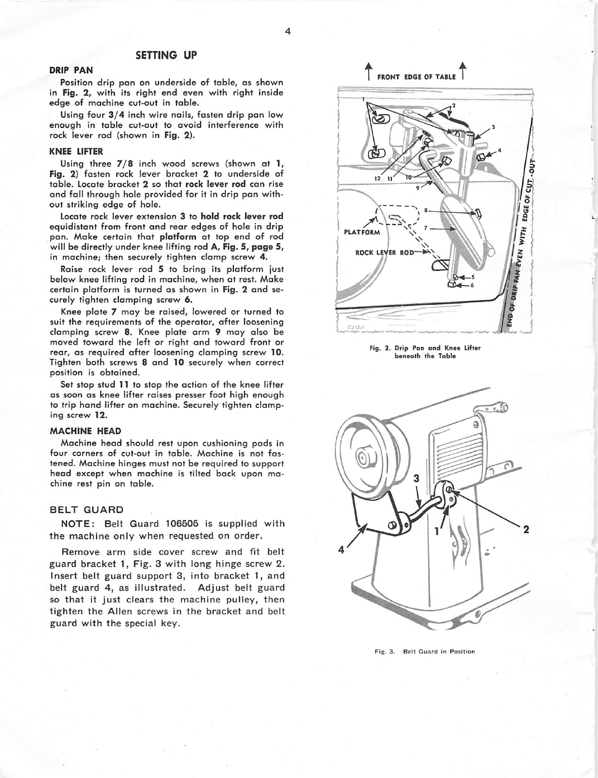
HOLD THIS END
ROLL
OVER
TOWARD
YOU
Fig,
t1.
How to Detormine Thread Twist
TO
SET THE NEEDLE
Turn machine pulley over away from you until
needle
bar
is
at
its
highest
point,
as
shown
in
Fig.
10,
page
6.
Loosen
needle
clamping
screw. Remove old
needle
and insert new needle up into needle
bar
as far as
it will
go.
Make certain
that
single continuous groove
of
needle faces
away
from hook
(toward
the
left end
of machine, as shown in Fig. 10, page 6) with eye
of
needle
directly
in
line
with
arm
of
machine.
Securely tighten clamping screw.
CHECK
NEEDLE
OFTEN
TO
MAKE
SURE
THESE
DEFECTS
ARE
NOT
PRESENT . . .
•
Wrong
needle
for
thread
and
material
in use—
a
cause
of
threod
breakage.
•
Bent
needle, clogged needle eye or dirty needle
groove—causes
of
skipped
stitches.
•
Hook
or burr on
needle
point—cause
of
picking
or
fraying
of
material.
•Incorrect
setting
of needle—a
cause
of
needle
breakage.
THREAD
Left
twist
thread
should
be
used
in
needle.
Either
right
or
left
twist
thread
can
be
used
in
bobbin.
Hold
thread
as
shown in Fig. 11. Twirl
thread
over
toward you between thumb and forefinger of right
hand; if left
twist,
strands
will
wind tighter; if right
twist, strands will unwind or separate.
Rough
or uneven thread, or thread which passes
with difficulty through the eye of the needle, will
interfere
with
successful
use
of
machine.
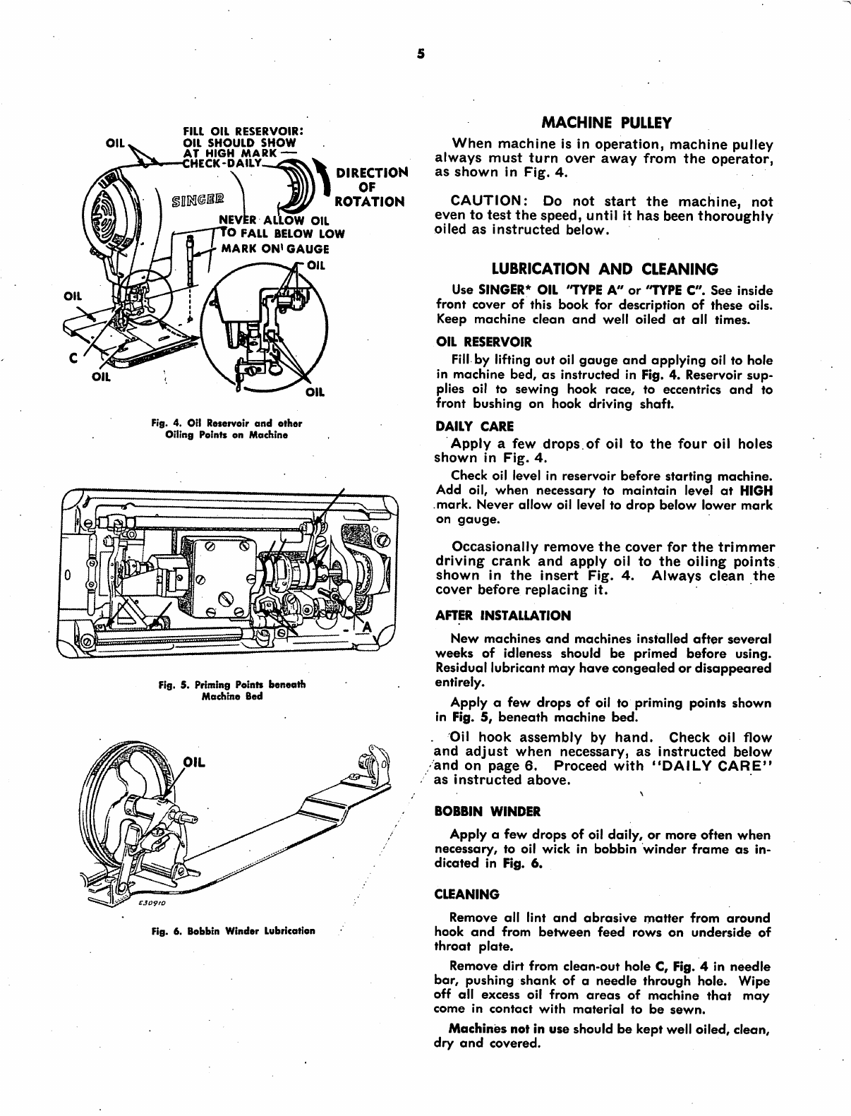
m
WRAP
THREAD
l'/2
TURNS
AROUND
DISC
UPPER
THREADING
Turn machine pulley
away
from
you until
needle
is
at
its highest
position.
Pass
thread
from
unwinder,
through
threading
points
#1
through
#12
in
order
shown
in
Fig.
12.
When
you
have
become
accus
tomed
to
threading
this
machine,
thread
can
be
passed
from
thread
ing
point
#4
to
needle
with
a
single
continuous
motion.
MOVE
TO
HIGHEST
POINT
Threading
the
Needle
7 5
to
/
\\
to
(Yi
Fig. 12. Upper Threading Completed
Thread
needle
from
left to
right.
Leave
about
three
inches
of
thread
behind
the
presser
foot,
as
shown
in
Fig.
12
with
which
to
start
sewing.
From the library of: Superior Sewing Machine & Supply LLC