Singer 251 User manual

SINGER
CLASS 251

From the library of Superior Sewing Machine & Supply LLC - www.supsew.com
2
USE
SINGER*
OILS
and
LUBRICANTS
They
insure
freedom
from
lubricating trouble and give
longer life
to
sewing equipment
The
following are
the
correct lubricants
for
the
241,251,253,
400w,
402w
and
4/0w
Machines:
TYPE
A -MANUFACTURING MACHINE
OIL,
LIGHT
GRADE
When
an
oil
is
desired
which will produce
a
minimum
of
stain on fabrics,
even
alter
a
long period
ol
storage, use:
TYPE
C -MANUFACTURING MACHINE
OIL,
LIGHT
GRADE
OTHER
SINGER
LUBRICANTS
TYPE
E -
THREAD LUBRICANT
For
lubricating
the
needle
thread
of
sewing
machines
for
stitching
fabrics
or
leather
where
a
thread
lubricant
is
required.
TYPE
F -MOTOR OIL
For
oil
lubricated
motors
and
plain
bearings
in
rower
tables
and
transmitters.
NOTE: All
of
the
above
oils
are
available
in
quart,
1 gallon and
5
gallon
cans.
BALL BEARING LUBRICANT
This
pure
grease
is
specially
designed
for
the
lubrication
of
ball
bearings
and
ball
thrust
bearings
of
motors
ond
electric
transmitters,
ball
bearing
hongers
of
power
tobles,
etc.
Furnished
in
1 lb. and 4 lb.
tins.
20549
SERVICE
MANUAL
FOR
SINGER.
SEWING MACHINES
OF
CLASS
251
LOCK STITCH
AUTOMATIC OILING
SYST~M
_J
CAUTION
-
See
that
the
oil reservoir
is
filled as
instructed
on
page
5
before
running
the
machine,
even
to
test
the
speed.
THE SINGER MANUFACTURING COMPANY
"A
T,ad,
Ma,k
of
THE
SINGER
MANUFACTURING
COMPANY

From the library of Superior Sewing Machine & Supply LLC - www.supsew.com
Copyright
(D
1955,
by
The
Singer
Manufacturing
Company
3
DESCRIPTION
Machines
of
Class 251
are
high
speed,
single
needle,
lock
stitch
machines
with
a
completely
automatic
lubricating
system.
They
have
a
gear
driven,
lubricated,
rotary
sewing
hook
on
a
horizontal
axis
and
a
drop
feed.
The
rotary
sewing
hook
makes
two
revolutions
for
each
stitch.
The
bed
of
these
machines
is
18-3/
4
inches
long
and
7
inches
wide.
The
space
at
the
right
of
the
needle
is
11
inches.
The
machine
base
and
oil
reservoir
furnished
with
these
machines
will
fit
any
table
cut-out
provided
for
Machines
of
Classes
31-,
96-
and
241-.
A
centrifugal
oil
pump
delivers
oil,
under
pressure,
to
all
the
prin-
cipal
bearings.
Provision
is
also
made
to
automatically
lubricate
all
the
other
bearings
in
the
machine.
The
needle
thread
take-up
lever
is
covered
by
an
oil
guard
to
pre-
vent
splashing
of
excess
oil.
An
oil
flow
window,
in
direct
view
of
the
operator,
indicates
the
circulation
of
oil
inside
the
arm
of
the
machine.
The
machine
pulley
furnished
is
for
a
3/8
inch
V-belt.
It
can
be
used
for
a
5/16
inch
round
belt,
when
desired.
These
machines
are
furnished
with
a
knee
lifter,
which
is
an
in-
tegral
part
of
the
machine
base
and
oil
reservoir.
Machine 251-1
has
a
needle
bar
stroke
of
1-9/64
inches
and
a
presser
bar
lift
of
9/32
inch;
can
sew
a
maximum
of
7
stitches
to
the
inch
and
is
designed
for
sewing
light
weight
fabrics.
Machine
251-2
has
a
needle
bar
stroke
of
1-13/64
inches
and
a
presser
bar
lift
of
5/16
inch;
can
sew
a
maximum
of
5-1
/2
stitches
to
the
inch
on
medium-heavy
to
light weight:j:
fabrics.
Machine
251-3
has
a
needle
bar
stroke
of
1-7/16
inches
and
a
presser
bar
lift
of
3 8
inch;
can
sew
a
maximum
of
5-1
/2
stitches
to
the
inch
on
heavy
to
light weight:j:
fabrics.
This
machine
can
also
be
furnished
with
a
presser
bar
lift
of
7
/16
inch,
enabling
it
to
sew
extra-
heavy
to
light weight!:
material.
·/·For
best
performance
on
light
weight
fabrics,
it
is
recommended
that
Machines
251-2
and
251-3
be
equipped
with
fittings
designed
for
the
particular
operation.

From the library of Superior Sewing Machine & Supply LLC - www.supsew.com
4
SPEED
The
maximum
speed
recommended
for
Machines
251-1
and
251-2
is
5000
revolutions
per
minute
and
for
Machine
251-3,
4300
revolutions
per
minute
according
to
the
material
being
sewn
and
the
type
of
work
being
done.
It
is
advisable
to
operate
these
machines
at
a
more
moderate
speed
the
first
few
days,
after
which
they
can
be
operated
at
maximum
speed.
When
the
machine
is in
operation,
the
top
of
the
machine
pulley
must
always
turn
over
toward
the
operator.
SETTING
UP
When
shipped,
the
base
is
held
to
the
machine
by
a
single bolt
through
the
bottom
of
the
base.
Discard
this
bolt
and
plug
the
hole
by
inserting
from
inside
the
base,
the
special
cap
screw
K,
Fig. 3,
fur-
nished
with
the
machine.
The
base
fits
into
a
standard
table
cut-out
and
rests
on
the
four
corners
without fastening.
Rasp
the
edges
of
the
cut-out,
if
necessary,
as
the base must slide
in
without driving
and
must
be
lo-
cated
so
that
the
machine head
does not touch the table
when
it is
placed
on
the
base.
Use
shims
on
the
corners,
if
nec-
essary,
to
prevent
the
base
from
rocking.
The
base
should
also
be
level
in
both directions
so
that
the
oil
level
will
be
accurately
indi-
H
cated
by
the
marks
in
the
base.
Fig. 2.
Installation
of
Knee
Lifter
See
that
the
plunger
L,
Fig.
3 is in
place
inside
the
base,
before
putting
the
machine
on
the
base.
The
machine
head
rests
on
the
cork
gasket
in
the
base
and
is
not
fastened.
The machine hinges must not support the head
except
when
it is
tilted
back.
The
knee
lifter
is
shipped
assembled
to
the
base,
except
for
the
knee
plate
and
lever
J,
Fig.
2.
After
the
base
is
in
position,
loosen
the
set
screws
D
and
E,
Fig. 2
and
slide
the
shaft
forward
to
the
position
shown
in Fig. 2.
Attach
the
knee
lifter
lever
J.
Set
the
stop
screw
F
so
that
there
is
only a little
play
of
the lifter before it starts
to
lift the
presser
bar,
then
hold
the
screw
and
tighten
lock
nut
G.
Set
the
rear
stop
dog
H
to
allow
the
presser
bar
to
be
just
raised
to
its
limit
but
not
enough
to
permit
further
strain
on
the
knee
lifter
parts
or
to
permit
the
action
of
the
knee
lifter
to
lift
the
machine
from
its
base.
CAUTION:-Before
starting
the
machine,
it
must
be
thoroughly
oiled,
in
accordance
with
the
following
instructions.
s
LUBRICATION
Machines
of
Class
251
have
an
automatic
lubricating
system
in
which
oil is
circulated
from
a
reservoir
in
the
base.
See
X-Ray
view
of
machine
on
pages
24
and
25.
TURN BACK
MACHINE
I
/
.:-:-:::
=--~
/~/
~
K L NEVER ALLOW
FILL
TO
OIL TO
FALL
HIGH
MARK
Fig.
3.
Oil
Reservoir
BELOW LOW
MARK
BEFORE
STARTING
THE
MACHINE,
the
oil
reservoir
must
be
filled
as
instructed
in
Fig.
3,
with
"TYPE
A"
or
"TYPE
C"
OIL,
sold
by
Singer
Sewing
Machine
Company.
For
description
of
these
oils,
see
inside
front
cover
of
this
book.
NOTE:
Before
starting
a
machine
which
has
been
standing idle
for
several weeks,
it
is
advisable
to
remove
the
face
plate
and
oil
the
needle
bar
and
take-up
bearings.
The
automatic
oiling
system
will
lubricate
these
bearings
after
the first
few
minutes.
When
in
operation,
the
oil
level
in
the
reservoir
should
be
inspected
at
least
twice
a
month,
or
as
often
as
necessary,
to
keep
it
from
going
below
the
LOW
mark,
see
Fig.
3, in
the
reservoir.
The
correct
operation
of
the
lubricating
system
is
shown
by
a
continuous
stream
of
oil
passing
through
the
oil
flow
window,
as
shown
in
Fig. 4,
while
the
machine
is
running.
CAUTION
If
the
oil
flow
should
stop,
the
machine
should
be
stopped
and
not
run
again
until
the
cause
has
been
determined.
See
instructions,
covering
Oil
Removing
Wick
Assembly,
on
pages
38
to
41.
SHOULD
SHOW
STEADY
OIL
FLOW
Fig. 4. Oil Flow
Window

From the library of Superior Sewing Machine & Supply LLC - www.supsew.com
6
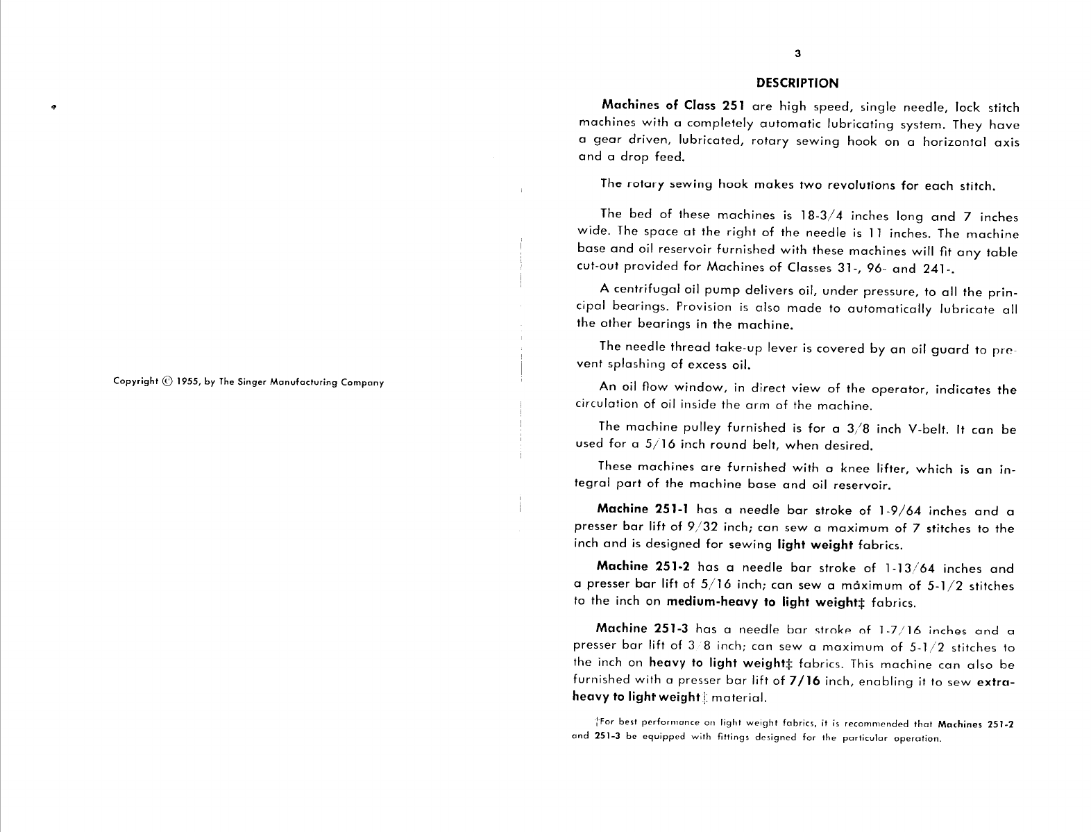
ADJUSTMENT OF ROTATING
HOOK
OIL FLOW REGULATOR
The
sewing
hook
is
automatically
lubricated.
The flow
of
oil
rs
controlled
by
the
oil
flow
regulator
illustrated
below.
1
-----·
143350
"~.,,
I
, . :
"'
:
...
-~,;
_-1=-
-b~:::::~
- -
~~'\---=
E2;!4//
~
140551
Fig. 5. Oil Flow
Regulator
in Hook
Shaft
Bushing
The oil
flow
regulator
is
set
at
the
factory
for
automatic
lubrica-
tion
of
the
hook
under
average
sewing
conditions.
If
more
or
less oil
is
desired,
turn
the
adjusting
thumb
screw
140551,
Fig. 5, clockwise to
increase
the
flow
of
oil
to
the
hook,
as
indicated
by
the
(+)
sign
under
its
arrow
on
the
head
of
the
thumb
screw,
or
turn
it
counter-
clockwise to decrease
the
flow,
as
indicated
by
the
(-)
sign
under
its
arrow
on
the
head
of
the
thumb
screw
140551.
To
determine
whether
the
oil
is
properly
flowing
to
the
hook,
withdraw
the
bed
slide
and
hold
a
piece
of
thin
paper
under
the
hook
while
the
machine
runs
for
ten
seconds.
There
should
be
a
slight
trace
of
oil
on
the
paper.
If
there
is
not,
adjust
the
oil
flow
regulator,
as
instructed
above,
or
replace
the
oil filter
143350,
Fig. 5,
in
the
head
of
the
hook
shaft,
as
instructed
on
page
32.
HINTS FOR
PERFECT
OPERATION
When
in
operation,
the
top
of
the
machine
pulley
must
always
turn
over
toward
the
operator.
Do
not
run
the
machine
with
the
presser
foot
resting
on
the
feed
without
cloth
under
the
presser
foot.
Do
not
run
the
machine
when
both
bobbin
case
and
needle
are
threaded
unless
there
is
material
under
the
presser
foot.
Do
not
try
to
aid
the
machine
by
pulling
the
fabric
lest
you
bend
the
needle.
The
machine
feeds
the
work
without
assistance.
The
slide
over
the
bobbin
case
should
be
kept
closed
when
the
machine
is
in
operation.
If
the
sewing
hook
should
become
excessively
warm,
it
may
be
due
to
an
insufficient
supply
of
oil
lo
the
hook
(see
instructions,
above,
for
adjusting
oil
flow
regulator).
NEVER
TOUCH
THE
STITCH REGULATOR PLUNGER WHILE
THE
MA-
CHINE
IS
RUNNING.
7
NEEDLES
Needles
for
Machines
of
Class
251
are
as
follows:
PRESSER
TYPE
NEEDLES
--
- - . -
----
MACHINE
BAR
OF CLASS
AND
LIFT
MATERIAL VARIETY SIZES
251-1 9
/32
inch
Light
88
X 9 8, 9, 10, 11, 12, 13,
14, 16, 17, 18, 19,
20,
21,
and 22
-
--
- - -
--
-------
-
--
------
251-2
5/16
inch
Medium-Heavy
8, 9, l 0, 11, 12, 13,
to
Light
16
X
257
14, 16, 17, 18, 19,
~-----·-
----
-
-----
-
--------------
- - -
--
20,
21,
22,
23,
and
251-3
3/8
inch
Heavy
to
Light
Regular
24
---
251-3
7/16
inch
Extra-Heavy
]6
X
261
16, 18, 19,
21,
22,
to
Light and 23
The
above
needles
are
regularly
nickel
finish
but
are
available
with
chromium
finish if
so
ordered.
The
size
of
the
needle
to
be
used
should
be
determined
by
the
size
of
the
thread
which
must
pass
freely
through
the
eye
of
the
needle.
Rough
or
uneven
thread,
or
thread
which
passes
with
difficulty
through
the
eye
of
the
needle,
will
interfere
with
the
successful
use
of
the
machine.
Orders
for
needles
must
specify
the
Quantity
required,
the
Size
number,
also
the
Class
and
Variety
numbers,
separated
by
an
x.
The
following
is
an
example
of
an
intelligible
order:
"l
00
No.
16,
88
x 9
Needles."
The
best
stitching
results
will
be
obtained
by
using
needles
sold
by
Singer
Sewing
Machine
Company.
THREAD
Left
twist
thread
should
be
used
in
the
needle.
Either
right
or
left
twist
thread
can
be
used
in
the
bobbin.
HIS END
l.21974
Fig. 6.
How
to
Determine
the Twist
To
determine
the
twist,
hold
the
thread
as
shown
above.
Roll
the
thread
over
toward
you
between
the
thumb
and
forefinger
of
the
right
hand;
if
left
twist,
the
strands
will
wind
tighter;
if
right
twist,
the
strands
will
unwind.

From the library of Superior Sewing Machine & Supply LLC - www.supsew.com
8
RELATIVE
SIZES
OF
NEEDLES
AND
THREAD
The
following
sizes
of
needles
and
thread
are
recommended
ac-
cording
to
the
class
of
work:
SIZES SIZES
OF
OF
CLASSES OF
WORK
COTTON,
LINEN
NEEDLES OR SILK
Shirtings,
Sheetings,
Calicoes,
Muslins,
60
to
80
Cotton
14
Silks, Dress
Goods
and
all
classes
of
A
and
BSilk
general
work.
---
--
-·---------------
16 All
kinds
of
heavy
Calicoes,
light
40
to
60
Cotton
and
Woolen
Goods,
heavy
Silk,
Seaming,
C Silk
17
Stitching,
etc.
-
------------
---------
Tickings,
Upholstery,
Woolen
Goods,
30
to
40
Cotton
18
Trousers,
Boys'
Clothing,
Cloaks,
etc. D Silk
Heavy
Woolens,
Tickings,
Bags,
Heavy
20
to 30
Cotton
19
Coats,
Trousers,
Heavy
Clothing
gen
er-
ESilk
ally.
--------
----
21
Bags,
Coarse
Cloths
and
Heavy
Goods.
TO
SET
THE
NEEDLE
Turn
the
machine
pulley
over
toward
the
operator
until
the
needle
bar
moves
to
its
highest
point.
After
loosening
needle
set
screw,
insert
needle
UP
into
needle
bar
AS
FAR
AS
IT
WILL
GO,
as
instructed
in Fig. 7.
NOTE:
The
needle
is
held
in
place,
in
Machines
251-2
and
251-3,
by
means
of
a
needle
clamp
instead
of
by
means
of
the
set
screw
in
the
needle
bar
as
in
Machine
251-1,
illustrated
in
Fig.
7.
The
single
continuous
groove
of
the
needle
MUST
face
the
left
end
of
the
machine,
as
shown
in
Fig
7.
----
~
60
to 80 Linen
16
to
20
Cotton
40
to
60
Linen
MOVE
TO
~HIGHEST
POINT
(f_~
----
LOOSEN
SCREW
·~
INSERT
NEEDLE
UP
AS
FAR
AS
POSSIBLE
Securely
tighten
needle
set
screw.
Fig. 7. Setting the
Needle
(Machine
25
I•
I)
9
UPPER
THREADING
NOTE:
The
take-up
lever
oil
guard
should
NOT
be
removed
when
threading
the
machine.
It
is
removed
in
Fig.
8
only
to
show
the
entire
path
of
the
needle
thread.
Pass
the
needle
thread
from
the
unwinder
through
the
threading
points
in
the
order
shown
in
Figs.
8
and
9.
0
Fig. 8.
Upper
Threading
Fig. 9.
Threading
the
Needle
Draw
about
two
inches
of
thread
through
the
eye
of
the
needle
with
which
to
commence
sewing.

From the library of Superior Sewing Machine & Supply LLC - www.supsew.com
10
TO REMOVE
THE
BOBBIN
I~
1.
MOVE
TAKE-UP
TO HIGHEST
POINT
Fig. 10. Preparing for
Removal of Bobbin
3. HOLD LATCH
AND
PULL
CASE
FROM
HOOK
Turn
the
machine
pulley
over
toward
the
operator,
until
the
1
needle
thread
take-up
lever
is
at
its
highest
point
as
shown
in
Fig. 10.
Reach
beneath
the
bed
of
the
machine
with
the
ldt
hand
and
remove
the
bobbin,
as
in-
structed
in Figs.11
and
12.
2.
OPEN
LATCH
Fig. 11. Removing Bobbin
Case
from
Sewing
Hook
NOTE:
While
the
latch
is
kept
open,
the
bobbin
will
be
retained
in
the
bobbin
case.
To
remove
the
bobbin
from
the
bobbin
case,
release
the
latch,
turn
the
open
end
of
the
bobbin
case
downward
and
the
bobbin
will
drop
out,
as
shown
inFig.12.
4.
RELEASE
LATCH\
5.
BOBBIN i
DROPS l
OUT
Fig. 12. Removing
the
Bobbin
11
TO
WIND
THE
BOBBIN
See
Fig. 13.
Fasten
bobbin
winder
to
table
with
its
driving
pulley
in
front
of
the
machine
belt,
as
shown
below,
so
that
pulley
will
move
away
from
belt
when
sufficient
thread
has
been
wound
upon
the
bobbin.
PLACE BOBBIN
ON
SPINDLE
Fig.
13.
Winding
the
Bobbin
Place
bobbin
on
spindle,
pushing
it
on
as
far
as
it
will
go
and
pass
thread
through
threading
points,
as
shown
above.
Wind
end
of
thread
around
the
bobbin
a
few
times.
Press
down
on
thumb
latch,
pushing
driving
pulley
over
against
belt,
as
shown
in
Fig. 13.
Start
machine.
Bobbin
winder
will
stop
automatically,
when
the
amount
of
thread
for
which
it is
regulated
is
wound
upon
the
bobbin.
For
more
thread
on
bobbin,
turn
screw
A
inward;
for
less
thread
on
bobbin,
turn
screw
A
outward.
When
winding
a
bobbin
with
fine
thread,
a
light
tension
should
be
used.
Adjust
the
knurled
nut
X, Fig. 13, to
regulate
the
tension.
If
thread
winds
unevenly
on
bobbin,
loosen
screw
B
and
move
tension
bracket
C
to
the
left
or
right,
as
required.
Tighten
screw
B.
Bobbins
can
be
wound
while
the
machine
is
stitching.
NOTE:
Occasionally
apply
a
few
drops
of
oil
to
the
oil
well,
shown
in Fig. 13,
on
top
of
the
bobbin
winder
frame.

From the library of Superior Sewing Machine & Supply LLC - www.supsew.com
12
TO
THREAD
THE
BOBBIN
CASE
Hold
the
bobbin
so
that
the
thread
will
unwind
in
the
di-
rection
shown
in Fig. 14.
Hold
the
bobbin
case
as
shown
in Fig. 14
and
place
the
bobbin
into
it.
~;~LL
2
►
Y
{ THREAD
DRAW
THREAD
INTO
UNDER SPRING
SLOT
Fig.
15. Pulling
the
Thread
into
the Slot
SLOT
NEAR
TOP
"y,
Fig. 14. Placing Bobbin
in Bobbin
Case
Pull
the
thread
into
the
slot
1
and
under
the
tension
spring
2,
Fig. 15.
3.
DRAW
THREAD
INTO
~LIVERY
ft
EYE
V
'Ji
Draw
the
thread
into
the
delivery
eye
at
the
end
of
the
tension
spring,
as
shown
in Fig. 16.
Fig. 16.
Drawing
the
Thread
Under
the
Tension Spring
13
TO
REPLACE
THE
BOBBIN
1. REPLACE
BOBBIN
CASE
ON
STUD
'
2.
RELEASE
LATCH
3.
PRESS
BACK
UNTIL LATCH CATCHES
GROOVE
IN
STUD
Fig. 17. Bobbin
Case
Threaded
and
Replaced
After
threading,
take
bobbin
case
by
latch
in
the
left
hand
and
place
bobbin
case
on
center
stud
of
bobbin
case
holder,
as
instructed
in Fig. 17.
Release
latch.
Press
bobbin
case
back
until
latch
catches
groove
near
end
of
stud.
Allow
about
two
inches
of
thread
to
hang
free.

From the library of Superior Sewing Machine & Supply LLC - www.supsew.com
14
TO
PREPARE
FOR SEWING
Hold
slack
end
of
needle
thread
loosely
and
turn
machine
pulley
over
toward
you
until
needle
moves
down
and
up
again
to
its
highest
point,
catching
bobbin
thread.
Draw
up
needle
thread;
bobbin
thread
will
come
up
with
it
through
hole
in
throat
plate,
as
shown
in
Fig. 18. Lay
both
threads
back
under
presser
foot.
fJ
V
Fig. 18.
Drawing
Up
the
Bobbin
Thread
TO COMMENCE SEWING
Place
material
beneath
the
presser
foot,
lower
the
presser
foot
and
commence
lo
sew,
turning
the
machine
pulley
over
toward
you.
15
TO
REMOVE
THE
WORK
1. Let
the
thread
take-up
lever
rest
at
its
highest
point.
2. Raise
the
presser
foot.
3.
Draw
the
work
toward
the
rear
until it
is
clear
of
the
needle.
4.
Cut
the
threads
close
to
the
goods.
TENSIONS
For
ordinary
stitching,
the
needle
and
bobbin
threads
should
be
locked
in
the
center
of
the
thickness
of
the
material,
thus:
Fig.
19. Perfect Stitch
If
the
tension
on
the
needle
thread
is too tight,
or
if
that
on
the
bobbin
thread
is
too loose,
the
needle
thread
will lie
straight
along
the
upper
surface
of
the
material,
thus:
Fig. 20. Tight
Needle
Thread
Tension
If
the
tension
on
the
bobbin
thread
is too tight,
or
if
that
on
the
needle
thread
is too loose,
the
bobbin
thread
will lie
straight
along
the
under
surface
of
the
material,
thus:
Fig. 21. Loose
Needle
Thread
Tension

From the library of Superior Sewing Machine & Supply LLC - www.supsew.com
16
TO
REGULATE
THE
TENSION
ON
THE
NEEDLE
THREAD
lESS
TENSION
Fig.
22.
Regulating
Needle
Thread
Tension
Tension on the needle
thread should be regulated
only
when
the presser foot
is
down.
Tension
on
the
needle
thread
should
be
just
enough
to
set
the
stitch
properly
in
the
material.
Having
lowered
the
presser
foot,
turn
the
thumb
nut
at
the
front
of
the
ten-
sion
discs,
as
instructed
in
Fig.
22.
TO
REGULATE THE TENSION
ON
THE BOBBIN THREAD
When
the
tension
on
the
bobbin
thread
has
been
once
prop-
erly
adjusted,
a
correct
stitch
can
usually
be
obtained
by
varying
the
tension
on
the
needle thread only.
For
average
sew-
ing
the
tension
on
the
bobbin
thread
should
be
very
light.
To
regulate
the
ten-
sion
on
the
bobbin
thread,
remove
the
bobbin
case
and
turn
the
screw
in
the
ten-
sion
spring,
as
in-
structed
in
Fig.
23.
MORE
TENSION
,........_~
__::#
LESS
TENSION
Fig. 23.
Regulating
Bobbin
Thread
Tension
17
TO REGULATE THE LENGTH OF STITCH
BEFORE
DEPRESSING PLUNGER (1)
MAKE
CERTAIN THAT
MACHINE
IS
NOT
RUNNING.
To
change
the
length
of
stitch,
depress
plunger
and
turn
machine
pulley,
over
toward
operator,
slowly,
until
plunger
drops
into
notch
in
the
feed
eccentric,
as
instructed
in
Fig.
24.
Then
turn
machine
pulley,
backward
or
forward,
until
numeral
representing
desired
length
of
stitch is
opposite
the
mark
on
the
front
of
the
arm.
UNTIL
PLU
1.
DEPRESS
_
_/
PLUNGER
....
~
::..,.,
'
'
DRQP.S
INTO N
!I
!l
·l
2. TURN
PULLEY
4.
THEN
TURN
PULLEY
TO
DESIRED
STITCH
LENGTH
Fig.
24.
Regulating
Length
of
Stitch
The
numeral
11
6
11
on
the
stitch
indicator
plate,
shown
above,
indi-
cates
the
longest
possible
stitch;
the
numeral
"30"
indicates
the
shortest
stitch.
Release
the
plunger
when
the
desired
setting
is
obtained.
TO PREVENT OPERATOR
FROM
CHANGING
STITCH LENGTH
The stitch
regulator
plunger
(see Fig. 24)
can
be
removed
to
prevent
an
unauthorized
person
from
changing
stitch
length.
To
remove
the
plunger,
remove
the
retaining
ring
near
the
tip
of
the
plunger,
allowing
the
plunger
to
be
withdrawn.
The
hole
in
the
top
cover
should
then
be
filled
by
inserting
a
plug
screw
140607,
which
can
be
obtained
at
an
additional
charge.

From the library of Superior Sewing Machine & Supply LLC - www.supsew.com
18
TO REGULATE
THE
PRESSURE
ON
THE
MATERIAL
The
pressure
on
the
material
should
be
as
light
as
possible,
while
still
sufficient
to
insure
proper
feeding.
MORE
PRESSURE
~
LESS~
PRESSURE
Fig. 25.
Regulating
the
Pressure
on
the
Material
Turn
the
thumb
screw,
shown
in
Fig.
25,
toward
the
right
to
increase
or
toward
the
left
to
decrease
the
pressure,
as
required.
TO
SET
THE
NEEDLE
BAR
AT
THE
CORRECT HEIGHT
See
that
the
needle
is
correctly
set
in
the
needle
bar,
as
instructed
on
page
8,
"TO
SET
THE
NEEDLE."
Then
remove
the
face
plate.
The
needle
bar
has
two
timing
marks
near
its
upper
end
(see Fig.
26).
Rotate
the
machine
pulley
over
toward
the
operator
until
the
needle
bar
moves
down
to
its
lowest
position.
The
upper
timing
mark
on
the
needle
bar
should
then
be
even
with
the
lower
end
of
the
needle
bar
bushing,
as
shown
in
Fig. 26.
To
set
the needle
bar
at
the correct height,
loosen
the
clamp
screw
M,
Fig.
26,
and
raise
or
lower
the
needle
bar
as
required.
Then
se-
curely
tighten
the
screw
M.
19
NOTE:
If
the
needle
bar
bushing
N,
Fig.
26
has
been
disturbed,
thus
making
it
impossible to use the
timing
marks,
loosen
needle
bar
bush-
ing
set
screw
P
and
raise
or
lower
the
bushing
N
as
required
to
bring
the
top
of
bushing
flush
with
top
of
machine
casting,
as
shown
in
Fig.
26.
Securely
tighten
set
screw
P.
The
needle
bar
should
then
be
set
at
the
correct
height
as
instructed
at
bottom
of
page
18.
,..-
...
,
p
____
____,;_::1):
'
'
' '
'
'
UPPER
~~~~G~'
/i~N
LOWER
~-M
4
TIMING
\\
MARK
NEEDLE
BAR
n
1
LOWE:/
POINTUt
Fig. 26. Setting
Needle Bar
HOOK
POINT
AT CENTER
OF
NEEDLE
'\
-
TT
~i
1/64"
~1u
..
'v"T
Fig. 27. Needle Bar
Set
at
Correct Height
Re-time
the
hook
as
instructed
on
page
24.
When
the
hook
is
correctly
timed
and
the
needle
bar
is
set
at
the
correct
height
the
top
of
needle
eye
will
be
approximately
l
/64
inch
below
the
point
of
the
hook
at
the
same
time
that
the
hook
point
is
at
the
center
of
the
needle.
See Fig.
27.
When
replacing
the
face
plate,
make
certain
that
the
screw
holes
in
the
face
plate
gasket
are
aligned
with
the
respective
screw
holes
in
the
face
plate,
avoiding
injury
to
the
gasket
and
consequent
oil
leakage.

From the library of Superior Sewing Machine & Supply LLC - www.supsew.com
20
ADJUSTMENT
OF
NEEDLE
THREAD
TAKE-UP
SPRING
SETTING
THE
HEIGHT
OF
THE
SPRING:
Thread
the
machine.
Turn
the
machine
pulley
over
toward
operator
until
take-up
lever
reaches
its
lowest
p::)int
and
begins
lo
rise.
0
HIGHER
~
;~~
f\w
DIP
5'
~
LOWER
LOOSEN
0~
\ R
Q
~
TIGHTEN
MORE
\
PRESSUR~
~
c~.Y~
R
~~Wu,,
s
Fig. 28. Setting
Fig. 29.
Adju,ting
Height
of Spring
Ten,ion
on
Spring
As
take-up
lever
begins
to
rise,
the
needle
thread
is
cost
off
the
hook.
The
HEIGHT
of
the
thread
take-up
spring
Q
should
be
set
so
that
al
this
point
(cast-off)
the
take-up
spring
will
"check"
(show
a
slight
dip)
and
return
to
rest.
later,
when
take-up
lever
approaches
lop
of
stroke,
ii
begins
lo
set
the
stitch,
causing
the
take-up
spring
lo
be
drawn
all
the
way
down.
As
take-up
lever
descends,
the
take-up
spring
will
return
lo
its
highest
point
(rest).
To
adjust
height
of
take-up
spring
Q,
loosen
set
screw
R
and,
by
turning
stud
S,
rotate
entire
take-up
assembly
over
toward
right
to
raise
the
spring
or
over
toward
the
left
to
lower
it.
Securely
tighten
set
screw
R.
NOTE:
Under
certain
conditions
of
tacking,
it
may
be
necessary
to
set
the
take-up
spring
higher
than
it is
otherwise
normally
set.
ADJUSTING TENSION ON
TAKE-UP
SPRING:
The
tension
on
the
thread
take-up
spring
Q
should
be
sufficient
to
ensure
its
action
at
high
speed.
However,
it
should
be
light
enough
to
permit
it
to
be
pulled
all
the
way
down
before
any
thread
is
drawn
through
the
tension
discs.
Before
adjusting,
make
certain
that
set
screw
R is
securely
tightened
so
that
when
stud
S
is
turned,
the
remainder
of
the
assembly
cannot
turn.
Also
make
certain
that
the
thumb
nut
is
in
place
on stud
S,
so
that
stud
may
be
turned
with
screwdriver
without
breaking.
To
adjust
tension on
take-up
spring,
turn
only
the
stud
S
(using
screwdriver
with
blade
large
enough
to
fit
snugly
into
slots
in
stud)
over
toward
right
to increase tension
or
over
toward
left
to
decrease
tension,
as
shown
in
Fig.
29.
NOTE:
The
tension
on
the
take-up
spring
may
require
different
settings
depending
upon
the
size
of
thread
used.
Heavier
thread
requires
more
tension
to
ensure
correct
thread
control.
CAUTION:
Take-up
spring
setting
must
be
checked
each
time
a
different
foot
is
applied
to
machine.
21
TO
SET
THE
PRESSER
BAR
AT
THE
CORRECT
HEIGHT
When
presser
bar
is fully
raised
by
presser
bar
lifter
and
needle
bar
is
at
its
lowest
position,
presser
foot
should
just
clear
bottom
of
needle
bar,
as
shown
in
Fig.
30.
When
presser
foot
rests
squarely
on
throat
plate,
with
feed
dog
below
throat
plate,
there
should
be
a
slight
amount
of
play
between
guide
bracket
T, Fig.
30
and
lifting
bracket
U, Fig.
30.
This will
permit
presser
foot
to
rest
firmly
upon
material.
I I
AT
AT
t
~
I
LOWEST
HIGHEST
~POINT
POINT
-
0
JUST
c.
CLEAR
Fig.
30.
Prener
Bar
Set
al
Correct
Height
To
adjust,
loosen
clamp
screw
V,
Fig.
30
and
raise
or
lower
guide
bracket
T,
as
required.
When
presser
bar
is
set
at
correct
height,
securely
tighten
screw
V.
CAUTION:
Whenever
guide
bracket
has
been
moved
on
presser
bar,
check
take-up
spring
for
correct
setting,
as
instructed
on
page
20.

From the library of Superior Sewing Machine & Supply LLC - www.supsew.com
22
TO
TIME
THE
SEWING HOOK
The
point
of
the
sewing
hook
should
be
at
the
center
of
the
needle,
as
shown
in
Figs.
31
and
32,
when
lower
timing
mark
on
needle
bar
reaches
the
bottom
end
of
needle
bar
bushing
N
during
the
upward
stroke
of
needle,
as
shown
in Fig. 31.
...
~N
0
tON
LOWER
TIMING
MARK
UPWARD
STROKE
L
Fig. 31. Timing
the
Sewing
Hook
Before
checking
timing
of
sewing
hook,
remove
presser
foot,
feed
dog,
slide
plate
and
throat
plate.
23
To
time
the
sewing
hook
turn
machine
pulley
over
toward
the
operator
until
lower
timing
mark
on
needle
bar
reaches
bottom
end
of
needle
bar
bushing
N,
on
upward
stroke
of
needle.
Then
loosen
two
hub
set
screws
X, Fig.
32,
in
hub
of
hook.
(The
two
screws
X
can
be
reached
from
top
of
bed
with
throat
plate
off.)
While
maintaining
position
of
needle,
as
described
above,
turn
hook
on
its
shaft
as
required
to
bring
hook
point
to
center
of
needle,
as
shown
in Fig. 32.
Make
certain
that
hub
of
hook
is
firmly
against
hook
shaft
oil
retaining
collar
K3,
as
shown
in Fig.
35,
then
securely
tighten
two
set
screws
X.
HOOK
POINT
AT
CENTER
OF
NEEDLE
\~
Fig.
32.
Sewing
Hook
Correctly
Timed
TO
SET
THE
SEWING
HOOK
SIDEWISE
IN RELATION TO
THE
NEEDLE
Sewing hook should never strike
needle.
\I
D5
j/HOOK
POINT
Fig.
33.
Clearance
Between
Hook
Point
and
Needle
I
'FLAT
OF
HOOK POINT
Fig.
34.
Checking
Clearance
Between
Needle
and
Flat
of
Hook
Point
When
point
of
sewing
hook
passes
needle,
clearance
between
hook
point
and
needle
at
DS,
Fig.
33
should
be
approximately
equal
to
thickness
of
a
piece
of
note
paper
(about
.005
inch),
as
shown
in Fig. 34.
Not
only
point
of
hook
but
FLAT
OF
HOOK POINT should clear needle
scarf
until
heel
of
flat
has
passed
the
needle.

From the library of Superior Sewing Machine & Supply LLC - www.supsew.com
24
..
:t_:~:-
.
'
.
.
.
"''~:it•~;,u,
,,,,,
""""'1,,-:"-

From the library of Superior Sewing Machine & Supply LLC - www.supsew.com
HOOK
HUB K3
~
X
26
Fig. 35. Hub of Hook
Firmly Against Oil
Retaining Collar
Before
adjusting
the
side-
wise
position
of
the
sewing
hook,
make
certain
that
hook
has
been
correctly
placed
on
the
hook
shaft;
the
hub
of
the
hook
firmly
against
the
hook
shaft
retaining
collar
K3,
as
shown
in Fig.
35.
See
also
in-
structions
on
page
23,
under
"TO
TIME
THE
SEWING
HOOK."
To
set the hook sidewise in relation to the needle:
Remove
bobbin
case,
as
instructed
on
page
10.
Loosen
hook
shaft
bushing
set
screw
Z3, Fig. 36.
/r
REMOVE
BOBBIN
CASE
r'}r----------
' I I
I I I
(])
:l!
1 J
HOOK
SHAFT
I
J~~-
--
i,--
--
--~
BUSHING
cs
K3
Fig.
36.
Hook
Shaft
Bushing
and
Hook
Assembly
f
I
• -~:J
HOOK
SHAFT
II I
27
S4
Jlj
KEEP
GEARS
IN
MESH
L2
Fig. 37. Loosening Hook Shaft Bevel
Gear
Loosen
the
two
set
screws
#1
and
#2,
on
the
hook
shaft
bevel
gear
S4, Fig.
37,
just enough to loosen the
gear
on
the
hook
shaft.
CAUTION:
MAKE CERTAIN THAT
THE
TWO
BEVEL
GEARS
L2
AND
S4
ARE
KEPT
IN
MESH
UNTIL
SET
SCREWS #1
AND
#2
ARE SECURELY
RETIGHTENED.
Using
a
light
mallet
and
a
1/4
inch
brass
drift
pin,
as
instructed
in Figs.
38
to
40,
move
the
hook
assem-
bly,
toward
or
away
from
the
needle,
as
required.
TAP
VERY
LIGHTLY
on
drift
pin
to
avoid
injury
to
hook
assembly.
~DO
NOT
i\X
HIT
BRIDGE
\PLACE
BRASS
DRIFT
PIN
HERE
Fig. 38. Where to Place
Drift
Pin
to Move Hook Assembly
Away
from
Needle

From the library of Superior Sewing Machine & Supply LLC - www.supsew.com
28
DO
NOT
HITBRIDG~
►
'f
~
TAP
VERY
LIGHTLY
;
¼"
BRASS
DRIFT
PIN
Fig. 39. Moving Hook
Assembly
away
from
Needle
DO NOT DAMAGE
Z3
' oc__
/
◄
BRASS
DRIFT
PIN
Fig.
40.
Moving Hook
Assembly
toward
Needle
G
TAP
1
LIGHTLY
When
the
point
of
the
hook
has
been
correctly
set
in
relation
to
the
needle,
securely
tighten
the
hook
shaft
bushing
set
screw
Z3,
Fig. 40.
29
Make
certain
set
screw
#1,
Fig.
37
(the
first
of
two
bevel
gear
set
screws
to
appear
as
the
machine
pulley
is
turned
over
toward
operator)
seats
over
flat
on
hook
shaft.
Remove
all
end
shake
from
hook
shaft,
by
pushing
hook
firmly
against
front
hook
shaft
bushing
and,
at
the
same
time,
pushing
gear
S4, Fig.
37
toward
the
hook
on
the
shaft.
Securely
tighten
first
set
screw
#1,
Fig.
37,
page
27,
then
tighten
set
screw
#2.
Time
the
sewing
hook,
as
instructed
on
pages
22
and
33.
Replace
the
bobbin
and
bobbin
case,
as
instructed
on
page
13.
FEED
ECCENTRIC
STOP
SCREWS
The
machine
is
prevented
from
making
longer
stitches
than
a
pre-
determined
maximum
by
the
stop
screw
W,
Fig. 41 in
the
feed
eccentric.
Feed
eccentric
stop
screw
140256,
furnished
with
Machine
251-1,
permits
a
maximum
length
of
seven
stitches
per
inch.
Stop
screw
140258,
for
14
stitches
per
inch
or
shorter,
can
also
be
used.
Machines
251-2
and
251-3
are
regularly
fitted
with
stop
screw
140257
permitting
a
maximum
length
of
5-1
/2
stitches
per
inch,
but
either
140256
(7
stitches
per
inch)
or
140258
(14
stitches
per
inch)
can
be
used.
Fig.
41.
Feed Eccentric
Stop
Screw

From the library of Superior Sewing Machine & Supply LLC - www.supsew.com
30
TO
TIME
THE
FEED
Before
the
machine
leaves
the
factory,
feed
lifting
eccentric-and-
bevel-gear
and
feed
eccentric
are
set
for
average
sewing conditions,
by
having
timing
screw
in
each
eccentric
enter
groove
provided
for
them
in
arm
shaft.
As
the
grooves
in
the
arm
shaft
are
not
visible
to
the
adjuster,
machine
pulley
should
be
turned
over
toward
operator
until
feed
lifting
eccentric
connecting
rod
A2, Fig.
42
is
at
its
lowest
position.
Timing
screw
Y,
Fig.
42
will
then
be
on
top
of
feed
lifting
eccentric-and-
bevel-gear.
Loosen
timing
screw
Y
and
set
screw
O
and,
while
main-
taining
this
position
of
gear,
turn
arm
shaft
until
timing
screw,
as
it is
slowly
tightened,
can
be
felt
to
drop
into
its
groove
in
arm
shaft.
Securely
tighten
timing
screw
Y
and
set
screw
0.
z
T
W
A2
0
Fig. 42. Timing the Feed
Feed
eccentric
timing
screw,
Z,
Fig.
42
appears
immediately
after
large
stop
screw
W, Fig.
42,
when
feed
eccentric
is
rotated
toward
operator.
Feed
eccentric
should
be
set
for
average
sewing
conditions,
by
having
this
timing
screw
Z
exactly
in
line
with
timing
screw
Y,
as
shown
in
Fig. 42.
Thus,
as
timing
screw
Z
is
tightened
it will
drop
into
its
groove
in
arm
shaft
which
is
in
line
with
groove
provided
for
feed
lifting
eccentric-and-bevel-gear
timing
sc:rew
Y.
Securely
tighten
tim-
ing
screw
Y
and
two
set
screws
in
feed
eccentric.
If,
for
any
reason,
it
is
necessary
to
alter
the
timing
of
either
eccentric,
timing
screw
should
be
removed
and
eccentric
locked
in
desired
setting
by
means
of
set
screws
only.
NOTE:
Whenever
the
timing
of
the
feed
is
changed,
sewing
hook
should
be
checked
for
necessary
adjustment
also,
as
instructed
on
pages 22
and
23.
31
TO
SET
THE
FEED
DOG
AT
THE
CORRECT
HEIGHT
FULL
DEPTH
REAR
TEETH
-==~~;,------
THROAT
PLATE
Fig.
43.
Showing
Feed Dog
at
Correct
Height
When
the
feed
dog
is
at
its
highest
position,
approximately
the
full depth
of
the
rear
teeth
of
the
feed
dog
should
project
above
the
top
zurface
of
the
throat
plate,
as
shown
in
Fig.
43.
Before
checking
the
height
of
the
feed
dog,
set
the
machine
for
the
longest
stitch,
as
instructed
on
page
17.
To
adjust,
loosen
the
clamping
screw
82, Fig.
44
and
raise
or
lower
the
feed
dog
(which
is
fastened
to
the
feed
bar
C2, Fig.
44)
as
re-
quired.
Then
securely
tighten
screw
82.
Fig.
44.
Adjusting
Height
of Feed Dog
TO
REMOVE
THE
SEWING HOOK
Remove
the
needle,
slide
plate
and
bobbin
case.
Remove
the
screw
D2, Fig.
44
and
the
bobbin
case
holder
position
bracket
E2, Fig. 44.
Loosen
the
two
set
screws
X,
Fig.
44
in
the
hub
of
the
hook
and
turn
the
machine
pulley
over
toward
the
operator
until
the
feed
bar
C2
is
raised
to its
highest
point.
Turn
the
sewing
hook
until
the
thread
guard
F2,
is
at
the
bottom,
as
shown
in
Figs.
45
and
46,
page
32.
Turn
the
bobbin
case
holder
G2,
until
the
notch
J2
is
also
near
the
bottom,
as
shown
in
Figs. 45
and
46.
The
sewing
hook
can
then
be
removed
from
the
hook
shaft.

From the library of Superior Sewing Machine & Supply LLC - www.supsew.com
32
Fig.
45.
Removing
and
Replacing
Bobbin
Case
Holder
(Correct Position
of
Bobbin
Case
Holder
in
Relation to
the
Sewing
Hook)
NOTE:
While
the
sewing
hook
is
off
the
shaft,
it
is
advisable
to
replace
the
oil filter
143350,
Fig.
45,
in
the
end
of
the
hook
shaft.
Unscrew
the
filter
from
the
center
of
the
shaft
al
H2, Fig.
45
and
replace
with
a
complete
new
filter
143350.
C2
~~-
~
~~
G2
-,
J2
F2
Fig.
46.
Removing
Sewing
Hook (Correct Position
of
Thread
Guard
and
Bobbin
Case
Holder)
TO
REPLACE
THE
SEWING
HOOK
When
placing
a
new
sewing
hook
on
the
shaft,
have
the
sewing
hook
thread
guard
F2
at
the
bottom
and
the
bobbin
case
holder
G2
turned
to
the
position
shown
in Fig.
46,
so
that
the
hook
will
clear
the
feed
bar
C2.
Place
the
hook
in
position
on
the
shaft
and
turn
the
bobbin
case
holder
G2
until
the
notch
J2
is
al
the
top.
Replace
the
bobbin
case
holder
position
bracket
E2,
Fig. 44,
making
certain
that
the
finger
K2,
Fig.
44
enters
the
notch
J2
(which
is
now
at
the
top
of
the
bobbin
case
holder.)
Then
securely
fasten
the
position
finger
by
means
of
the
screw
D2, Fig. 44.
Replace
the
needle.
Time
the
sewing
hook
as
instructed
on
pages
22
and
23.
Replace
the
bobbin
case
and
slide
plate.
33
TO REMOVE
AND
REPLACE
THE
HOOK
SHAFT
Remove
and
replace
the
hook
shaft
in
the
following
manner:-
1.
Remove
the
sewing
hook,
as
instructed
on
pages
31
and
32.
2.
Mark
the
two
lower
bevel
gears
L2
and
S4, Fig.
47,
with
chalk
or
crayon,
on
one
tooth
of
one
gear
and
the
corresponding
space
in
the
other
gear.
This
is
important,
as
these
gears
may
become
separated
during
removal
of
shaft.
These
marks
will
then
make
it
possible
to
obtain
the
original
relative
position
of
the
gears.
3.
While holding the
two
gears
L2
and
S4
in mesh,
as
instructed
in
Fig.
47,
loosen
the
two
set
screws
#1
and
#2
in
the
hook
shaft
bevel
gear,
withdraw
the
old
hook
shaft
and
insert
the
new
shaft.
N2
52;;:~
#2
VJ
Qi
/•1~
HOOK
sf,)f'iiiJJ
SHAFT
/._/
/L2
HOLD GEARS
IN
MESH
Fig.
47.
Removing
and
Replacing
Hook
Shaft
4.
Make
certain
that
set
screw
#1
(the
first
of
the
two
bevel
gear
set
screws
to
appear
as
the
machine
pulley
is
turned
over
toward
oper-
ator)
seats
over
flat
on
the
hook
shaft.
Remove
all
end
shake
from
hook
shaft,
by
pushing
hook
firmly
against
front
hook
shaft
bushing
and,
at
the
same
time,
pushing
gear
S4, Fig.
47
toward
the
hook
on
the
shaft.
Securely
tighten
first
set
screw
#1,
then
securely
tighten
the
second
screw
#2.
5.
Replace
the
sewing
hook,
as
instructed
on
page
32.
6.
Time
the
sewing
hook,
as
instructed
on
pages
22
and
23.
TO
REMOVE
THE
OIL PUMP
Remove
the
oil
pump
from
the
upright
arm
shaft,
in
the
following
manner:-
1. Loosen
the
two
oil
pipe
clamping
sleeve
nuts
S2, Fig.
47.
2.
Remove
the
four
screws
N2,
Fig.
47.
3.
Remove
the
screen
frame,
screen
and
oil
pump
cover
02,
Fig.
47.

From the library of Superior Sewing Machine & Supply LLC - www.supsew.com
34
4.
Remove
the
locking
screw
Q2, Fig.
48
from
the
center
of
the
up-
right
arm
shaft,
by
turning
it
over
toward
the
left
(counterclock-
wise).
5.
Remove
the
impeller
P2,
by
turning it over
toward
the RIGHT (clock-
wise)
to
loosen
it,
as
instructed
in
Fig.
48.
CAUTION: -
The
impeller
P2
is
designed
to
be
screwed
to
the
shaft
by
means
of
a
LEFT-HAND
THREAD
and
must
be
turned over
toward
the
right to be loosened.
Avoid
damage
to
this
impeller,
as
the
efficient
automatic
lubrication
of
the
machine
is
dependent
upon
it.
TO LOOSEN
Fig. 48. Oil
Pump
6.
Remove
the
three
screws
T2, Fig.
48.
7.
Carefully
pull
1he
old
oil
pump
body
off
the
lower
end
of
the
upright
arm
shaft.
TO
REPLACE
THE
OIL PUMP
Replace
oil
pump
in
the
following
manner:-
1.
Place
oil
pump
body
on
underside
of
machine
bed,
so
that
position
pins
V2,
slip
into
proper
holes
in
machine
casting
as
shown
in
Fig.
48.
2.
Replace
and
securely
tighten
the
three
screws
T2.
Make
certain
that
machine
turns
freely
as
screws
are
tightened.
3.
Carefully
replace
impeller
P2, turning it over toward the
LEFT
to
SCREW
it
on
arm
shaft
(see
CAUTION
above).
4.
Make
certain
that
impeller
P2
is
not
so
tight
that
it
will
bind
arm
shaft
and
that
impeller
clears
both
top
and
bottom
of
in-
terior
of
oil
pump
body,
then
lock it in
position
by
means
of
lock-
ing
screw
Q2.
5.
Replace
pump
cover,
screen
and
frame
02
and
four
screws
N2,
Fig.
47.
Securely
tighten
screws
N2.
6.
Replace
two
oil
pipes
in oil
pump
body,
as
shown
in
Fig.
48,
and
securely
tighten
sleeve
nuts
S2.
35
TO REMOVE
AND
REPLACE
THE
NEEDLE
BAR
Remove the needle
bar
in
the
follow-
ing
manner:-
].
Remove
needle
and
needle
set
screw
or
needle
clamp.
2.
Remcve
face
plate.
3. Loosen
clamping
screw
M,
Fig.
49
4.
Loosen
screw
R2
sufficiently
to
allow
needle
bar
to
pass,
then
slip
needle
bar
up
through
both
needle
bar
bushings
and
out
of
machine.
If
it
becomes
necessary
to
remove
upper
needle
bar
bushing
N,
Fig.
49,
first
remove
screw
R2
and
take-up
lever
oil
guard
W2.
Then
loosen
set
screw
P
and
drive
bushing
N
down
and
out
of
head
of
machine.
Use a
13/32
inch
driving
pin.
Before
replacing
needle
bar,
replace
upper
needle
bar
bushing
N,
by
driv-
ing
it
down
into
hole
provided
for
it in
head
of
the
machine.
Make
certain
top
of
bushing
N
is
level
with
top
of
arm.
Tighten
set
screw
P.
Replace
needle
bar
in
the
following
manner:-
1. Slip
needle
bar
down
through
both
Fig.
49.
Removing
and
Replacing
bushings
in
head
of
the
machine.
Needle
Bar
and
Presser
Bar
Tighten
screw
M.
2.
Replace
needle
clamp
and
needle.
See
page
8.
3.
Set
needle
bar
at
correct
height
and
replace
face
plate,
as
in-
structed
in
last
paragraph
on
page
19.
4.
Replace
oil
guard
W2
and
fasten
it
securely
to
bushing
with
set
screw
R2.
TO REMOVE
AND
REPLACE
THE
PRESSER
BAR
To
remove the presser
bar:-
1.
Remove
presser
foot
and
face
plate.
2.
Remove
presser
bar
regulating
thumb
screw,
X2,
Fig.
49
with
upper
section
of
presser
bar
from
the
head
of
the
machine.
3. Loosen
clamping
screw
V
and
screw
AS
and
slip
guide
bracket
T
up
off
presser
bar
and
out
of
machine.
4.
Slide
presser
bar
up
through
bushing
and
out
of
machine.
To
replace the presser
bar:-
1.
Slip
presser
bar
down
through
lower
presser
bar
bushing.
2.
Replace
guide
bracket
T
as
shown
in
Fig.
49.
3.
Replace
pres,;er
foot.
4.
Replace
presser
bar
regulating
thumb
screw
X2
with
upper
section
of
presser
bar.
5.
Set
the
presser
bar
at
the
correct
height,
as
instructed
on
page
21.
Tighten
screw
V.
6.
Tighten
screw
AS
making
sure
that
slack
thread
regulator
BS
just
clears
the
casting.
Replace
face
plate,
as
instructed
on
page
19.

From the library of Superior Sewing Machine & Supply LLC - www.supsew.com
36
TO REMOVE NEEDLE
BAR
LINK
AND
THREAD TAKE-UP
Remove
needle
bar
link
and
thread
take-up
in
the
following
manner:-
1.
Remove
face
plate
and
arm
hole
plug
A3,
Fig.
50
from
ma-
chine.
DO NOT
DISTURB
Z2
Y2
2.
Remove
needle
bar,
upper
needle
bar
bushing,
presser
bar
and
guide
bracket
T,
Fig.
51
as
instructed
on
page
35.
3. Loosen
set
screw
Y2,
Fig.
50
in
needle
bar
crank,
reaching
with
a
screwdriver
through
the
hole
in
the
arm,
opened
by
re-
moval
of
plug
A3,
and
turning
DO NOT
DISTURB
U2
machine
pulley
as
required.
Fig.
so.
Needle
Bar
Crank
4.
Using
wrench
146057
(through
same
hole)
and
turning
machine
pulley
as
required,
loosen
the
large
hexagon
head
clamping
screw
Z2, Fig.
50,
on
the
needle
bar
crank.
CAUTION:
DO
NOT
DISTURB the smaller
hexagon
head
position screw
U2, Fig.
50,
which
holds
the
needle
bar
crank
at
its
correct
position
on
the
horizontal
arm
shaft.
•;
~~3
G3
03
F3
W4
~
J3
Fig. 5
I.
Needle
Bar
Link
and
Thread
Take-up
H3
t
.5.
Loosen
small
set
screw
B3, Fig.
51
in
the
rear
of
the
arm
of
the
machine.
6.
Insert
a
face
plate
screw
E3,
Fig.
51
in
the
tapped
hole
in
center
of
stud
C3, Fig.
51
and,
while
holding
back
the
needle
bar
link
inside
the
head
at
G3,
Fig.
51,
pull
upon
the
screw
E3
until
the
stud
C3
is
removed.
Remove
face
plate
screw
from
stud.
7. Back
ti1e
end
of
the
take-up
H3, Fin.
51
toward
the
inside
of
the
machine
turning
the
ma-
chine
pulley,
as
required
until
the
takr>-up
is
free
of
the
slot
provided
for
it.
8. The
needle
bar
link
G3
and
take-up
HJ
con
now
be
pulled
free
of
the
needle
bar
crank
WITHOUT
DISTURBING
THE
NEEDLE BEAR-
INGS F3, Fig.
50.
..
37
NOTE:
If
the
needle
bearings
F3, Fig.
50,
are
accidentally
disturbed,
they
must
be
re-assembled
so
that
there
are
exactly
18
bearings
in
each
of
the
two
assemblies.
TO
REPLACE
THE
NEEDLE BAR LINK
AND
THREAD TAKE-UP
Replace
the
needle
bar
link
and
thread
take-up
in
the
following
manner:-
1.
Make
sure
that
the
wearing
plate
J3 is in
place
on
the
face
of
the
needle
bar
crank,
as
shown
in Fig.
51.
Place
the
needle
bar
link
G3
and
take-up
H3
in
the
head
of
the
machine
so
that
the
stud
in
the
center
of
the
linkage
slips
into
the
hole
provided
for
it in
the
needle
bar
crank,
as
shown
in Figs.
50
and
51.
2.
Slip
the
upper
end
of
the
take-up
H3
through
the
slot
provided
for
it in
the
head
of
the
machine.
3.
Insert
stud
C3
through
needle
bar
link
G3
and
into
its
hole
in
the
machine
casting
so
that
the
flat
on the stud faces the
rear
of
the
machine.
The
mark
03
on
the
stud
indicates
the
position
of
this
flat.
Fig.
51
shows
the
stud
with
the
mark
D3 in
the
correct
position
.
4.
When
the
stud
C3 is
fully
and
correctly
inserted,
turn
the
set
screw
B3
inward
lightly
against
the
flat
on
the
stud
C3.
5.
Insert
a
screwdriver
through
the
hole
in
the
front
of
the
head
of
the
machine
and
turn
machine
pulley
as
required
to
reach
set
screw
Y2
in
needle
bar
crank.
While
tightening
screw
Y2,
turn
stud
W4
by
hand
to
find
its
flat,
then
slightly tighten
set
screw
Y2
in
needle
bar
crank.
Make
certain
that
assembly
F3 is
firmly
against
wearing
plate
J3.
Produce
a
very
slight
side
play
by
pushing
take-up
lever
H3
gently
right
and
left;
then
securely
tighten
screw
B3.
6.
Using
wrench
146057
through
same
hole
and
turning
machine
pulley
as
required,
tighten
hexagon
head
screw
Z2.
7.
Securely tighten
set
screw
Y2.
8.
Replace
guide
bracket
T in
head
of
machine,
as
shown
in Fig.
51.
9.
Replace
and
adjust
presser
bar,
upper
needle
bar
bushing
and
needle
bar
with
their
accessories,
as
instructed
on
pages
19
and
35.
10.
Replace
and
securely
tighten
arm
hole
plug
A3.
11.
Replace
the
face
plate
(see
instructions
at
bottom
of
page
19).
Other manuals for 251
3
Table of contents
Other Singer Sewing Machine manuals

Singer
Singer 471U User manual

Singer
Singer Stilist Serger Owner's manual

Singer
Singer 152W1 Quick start guide

Singer
Singer 8280 User manual

Singer
Singer 469U Manual

Singer
Singer 72W19 User manual

Singer
Singer 457G1 User manual

Singer
Singer 6021 User manual

Singer
Singer 81-63 User manual

Singer
Singer 105-20 User manual

Singer
Singer 81-12 User manual

Singer
Singer 58-14 User manual

Singer
Singer 4843116 User manual

Singer
Singer 200B Setup guide

Singer
Singer 99W130 User manual

Singer
Singer M2405 User manual

Singer
Singer XL-580 User manual

Singer
Singer Fashion Mate 237 User manual

Singer
Singer 144W204 Quick start guide

Singer
Singer 97-1 Installation and operation manual