SingleTact SingleTact Standard User manual
USER MANUAL
EXPERIENCE
INCREDIBLE
PERFORMANCE
V2.3

pg. 2
Copyright © 2017- www.SingleTact.com
CONTENTS
1INTRODUCTION............................................................................................................................................... 3
2INTERFACE DESIGN ......................................................................................................................................... 4
2.1 Connectivity.............................................................................................................................................. 5
2.2 Analog Interface....................................................................................................................................... 6
2.3 I2C Interface.............................................................................................................................................. 7
2.4 I2C Operations ........................................................................................................................................ 10
2.4.1 I2C Write Operation ........................................................................................................................ 10
2.4.2 I2C Read Request Operation ........................................................................................................... 11
2.4.3 I2C Read Operation.......................................................................................................................... 11
2.5 Conversion Detail ................................................................................................................................... 13
2.6 Product Categories................................................................................................................................. 14
3TROUBLESHOOTING SingleTact .................................................................................................................... 15
3.1 Arduino UNO not detected by PC. ......................................................................................................... 16
3.2 Invalid setting error on PC (Popup reports” Failed to set”)................................................................... 16
3.3 No Analog output (remains at 0V). ........................................................................................................ 16
3.4 Analog output stays at 0.5V. .................................................................................................................. 16
4EXAMPLE USE CASE....................................................................................................................................... 17
4.1 PC and Arduino Example........................................................................................................................ 18
4.2 Programming the Arduino UNO with SingleTact Example..................................................................... 20
4.3 Arduino Demo Outline ........................................................................................................................... 22
4.4 Example .NET API ................................................................................................................................... 26
5Resources...................................................................................................................................................... 27
6Glossary......................................................................................................................................................... 28
7Revision History ............................................................................................................................................ 29
pg. 3
Copyright © 2017- www.SingleTact.com
1INTRODUCTION
SingleTact is a single element tactile pressure sensor that accurately and reliably quantifies applied
force combined with a simple interface board offering a 0 to 2V analog output for immediate Data
Acquisition (DAQ) integration and an I2C based interface for integration into embedded systems.
Standard and Calibrated sensors (with matched pre-calibrated interface board) are available.
This document provides all the information necessary to interface with the SingleTact including a
sample Arduino digital interface and simple C# PC DAQ software (see EXAMPLE USE CASE)
All demo and API source code is open source and can be downloaded from: www.singletact.com.
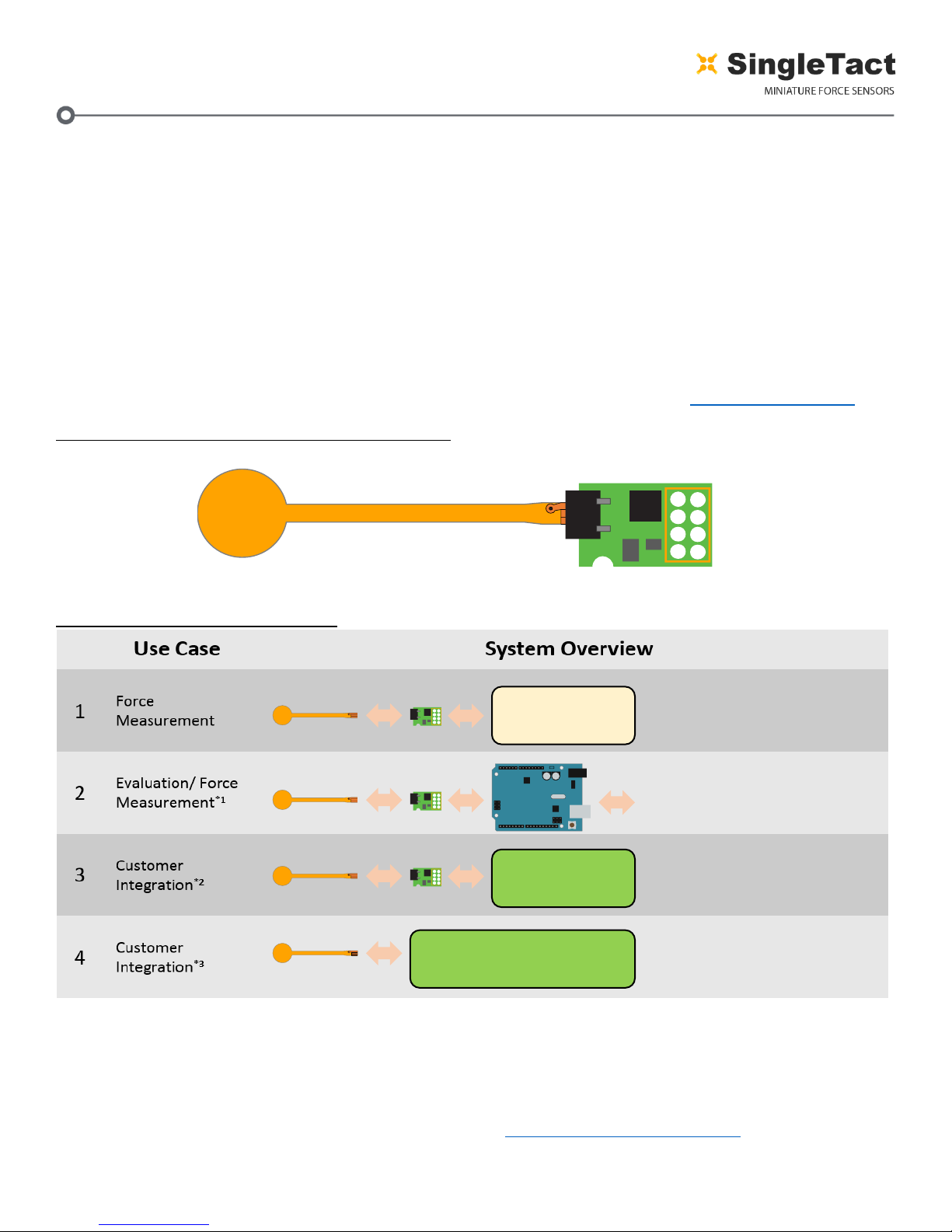
Figure 1 SingleTact Sensor and Interface Board
Figure 2 Use Case Configurations
*1 –In addition to the data acquisition example, a .NET library is available to download for simple integration into a user’s
own software suite. See Example .NET API.
*2 –Supports over 100 SingleTact interface boards on a single I2C bus. The interface board firmware can be modified to
fit user’s specific use cases – if required please contact PPS to discuss this option.
*3 –PPS maybe able to assist with this –use the contact links at http://www.singletact.com/contact/.
SingleTact.com
1
2
3
45
6
7
8
MCU
Single Tact.com
1
2
3
45
6
7
8
MCU
Arduino and PC data acquisition
evaluation software
Analogue Out. Connect to multitier,
oscilloscope or data acquisition card
User reads capacitance
using their own circuitry
Single Tact.com
1
2
3
45
6
7
8
MCU
UNO
Single Tact.com
I2C Digital Output. Interface to user
electronics
Single Tact.com
1
2
3
45
6
7
8
MCU
User
Hardware
Analog
Measurement
I2C
I2C
User
Hardware
pg. 4
Copyright © 2017- www.SingleTact.com
2INTERFACE DESIGN
pg. 5
Copyright © 2017- www.SingleTact.com
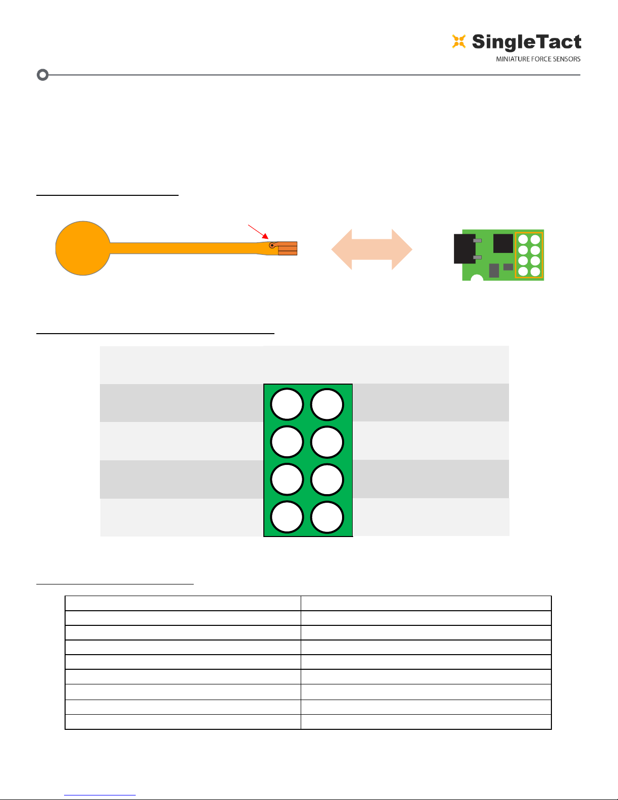
2.1 Connectivity
The sensor is plugged into the FFC connector on the green interface board (with the sensor
connector pads facing upward). The connections are outlined in Figure 4.
Electrical parameters are outlined in Table 1.
Figure 3 Sensor Assembly
Figure 4 Interface board header connections
Table 1 Electrical parameters
Parameter
Value
Supply Voltage, Vcc
3.7 –12V
I2C clock frequency
100KHz or 400KHz
I2C bus level
3 –5V
I2C output range (sensor data)
10-bit (Operational FSR output 9-bit)
Analog output range
0 –2V (Operational FSR output 0.5 –1.5V)
Permitted analog output load
>5K
Frame Sync level
3.3V CMOS output
Sensor update rate (I2C or analog)
>140Hz (dependent on settings)
SingleTact.com
1
2
3
45
6
7
8
MCU
Note via orientation
CONNECTION
Reserved
I2C Interface (SDA)
Frame Sync
Ground
1
4
3
2
8
5
6
7
CONNECTION
Reserved
I2C Interface (SCL)
Analog Out
Vcc
PIN
NUMBER
This manual suits for next models
1
Table of contents


