sinmag LBC LCR5 Guide

© 2017-2020 LBC BAKERY EQUIPMENT, INC. TULALIP, WA PG 1 REV 12/2020
Models LCR5 and LCR7
5-Spit and 7-Spit Rotisserie Ovens
Installation, Service and Parts Manual
LBC Bakery Equipment, Inc.
6026 31st Ave NE
Tulalip, WA 98271, USA
Phone: 888-RACKOVN (888-722-5686)
Fax: 425-642-8310
Email: parts@lbcbakery.com
Website: www.lbcbakery.com

2
READ FIRST T
THIS MANUAL MUST BE RETAINED FOR FUTURE REFERENCE. READ, UNDERSTAND AND FOLLOW
THE INSTRUCTIONS AND WARNINGS CONTAINED IN THIS MANUAL.
W A R N I N G
DO NOT STORE OR USE GASOLINE
OR OTHER FLAMMABLE VAPORS
AND LIQUIDS IN THE VICINITY OF
THIS OR ANY OTHER APPLIANCE.
D A N G E R
W A R N I N G
IMPROPER INSTALLATION,
ADJUSTMENT, SERVICE OR
MAINTENANCE CAN CAUSE
PROPERTY DAMAGE, INJURY OR
DEATH. READ THE INSTALLATION,
OPERATING AND MAINTENANCE
INSTRUCTIONS THOROUGHLY
BEFORE INSTALLING OR SERVICING
THIS EQUIPMENT.
C A U T I O N
ALWAYS KEEP THE AREA NEAR
THE APPLIANCE FREE FROM
COMBUSTIBLE MATERIALS.
This LBC Rotisserie was manufactured to rigid standards. The appliance has been tested and is listed by Intertek Testing
Services (ETL Semko) and meets applicable safety and sanitation standards.
A) The responsibility of the manufacturer is to supply suitable, comprehensive instructions and recommendations for
proper operation and maintenance.
B) All operations, maintenance and repair of this or any LBC Bakery Equipment appliance must be performed by
properly trained and qualified personnel, and all such operations, maintenance and repair must be performed in a
diligent manner. It is the responsibility of the owner/operator to ensure proper training and diligence of any person
coming into contact with either the subject units or the output (product, fumes or otherwise) of the subject units.
It is the responsibility of the owner/operator to ensure that the subject units are installed and operated in
accordance with OSHA Standard 1910.263.
C) A regular periodic program of cleaning, inspection and maintenance must be established and comprehensive
maintenance records maintained. It is the sole responsibility of the owner/operator to establish, schedule and
enforce the frequency and scope of these programs in keeping with recommended practice and with due
consideration given to actual operating conditions.
D) The appliance must be operated within limits which will not exceed its working limits. It is the responsibility of the
user to operate this appliance in accordance with the rules and limits described in this manual and the published
product specification sheet, and in accordance with the directions and instructions of the owner/operator of the
appliance or employer, and in accordance with applicable federal, state and local laws and ordinances.

3
TABLE of CONTENTS T
Read First . . . . . . . . . . . . . . . . . . . . . . . . . . . . . . . . . . . . . . . . . . . . . . . . . . . . . . . . . . . . . . . . . . . . . 2
Specifications . . . . . . . . . . . . . . . . . . . . . . . . . . . . . . . . . . . . . . . . . . . . . . ... . . . . . . . . . . . . . . . . 4
Configurations . . . . . . . . . . . . . . . . . . . . . . . . . . . . . . . . . . . . . . . . . . . . . . . . . . . . . . . . . . . . . . . . . 5
Conditions of Installation ....... . . . . . . . . . . . . . . . . . . . . . . . . . . . . . . . . . . . . . . . . . . . . . . . . . . 6
Receiving and Unpacking . . . . . . . . . . . . . . . . . . . . . . . . . . . . . . . . . . . . . . . . . . . . . . . . . . . . . . . . . 7
Installation . . . . . . . . . . . . . . . . . . . . . . . . . . . . . . . . . . . ....... . . . . . . . . . . . . . . . . . . . . . . . . . . . 8
Controller Operation . . . . . . . . . . . . . . . . . . . . . . . . . . . . . . . . . . . . . . . . . . . . . . . . . . . . . . . . . . . . 11
Parts List . . . . . . . . . . . . . . . . . . . . . . . . . . . . . . . . . . . . . . . . . . . . . . . . . . . . . . . . . . . . . . . . . . . . . . 12
Wiring Diagram . . . . . . . . . . . . . . . . . . . . . . . . . . . . . . . . . . . . . . . . . . . . . . . . . . . . . . . . . . . . . . . . . 17
Warranty . . . . . . . . . . . . . . . . . . . . . . . . . . . . . . . . . . . . . . . . . . . . . . . . . . . . . . . . . . . . . . . . . . . . . . 19

4
SPECIFICATIONS T
Model H* W D1D2D3D4Actual
Weight
Shipping
Weight Freight Class
LCR5 32.5"
31.5" 21.7" 26.3" 27.1" 24.3"
320
lbs
450 lbs 85
LCR7 38.4" 38.9" 26.5" 32.6" 32.6" 31.6"
460
lbs
610 lbs 85
Model Voltage kW Min Circuit Ampacity Max Breaker Size
1 Phase
3 Phase
1 Phase
3 Phase
LCR5
208 VAC
4.0
40
N/A
60
N/A
LCR7
208 VAC
9.0
N/A
40
N/A
60

5
CONFIGURATIONS S
Rotisserie
Stacked Appliances
6.0” Legs or
4.5” Swivel Casters with Brakes
Countertop: 4.0” Legs
Floor: 6.0” Legs or
4.5” Swivel Casters with Brakes
Rotisserie
Countertop or
Floor Mount
Stand Mount
LST5 Stand (for LCR5 Rotisserie) or
LST7 Stand (for LCR7 Rotisserie or
LHC7 Holding Cabinet)
Combinations:
•2 ea LCR5 Rotisseries
•2 ea LCR7 Rotisseries
•1 ea LCR7Rotisserie + 1 ea LHC7 Holding Cabinet
NOTE: When a Rotisserie is stacked with a
Holding Cabinet, It may be installed on the top
or bottom

6
CONDITIONS of INSTALLATION I
LBC Bakery Equipment Co. shall, for a fee contingent on site location and provided that the conditions of installation
are met, provide a factory-authorized service agency to install the LBC Rotisserie. The job site must be ready for the
installation before LBC Bakery Equipment Co. or its authorized agent arrives. If the installation site is not properly
prepared or if there are construction delays, the customer shall be responsible for all expenses incurred during this
delay. All expenses resulting from job delay or extension, for reasons beyond the control of LBC Bakery Equipment
Co., shall be the responsibility of the customer. Installation shall be conducted during normal business hours. This
installation is for a single trip. Start-up and training are not included.
IN ALL CASES, THE ELECTRICAL, MECHANICAL CONNECTIONS AND VENTILATION MUST MEET ALL FEDERAL, STATE
AND LOCAL CODES OR ORDINANCES.
It is the responsibility of the owner/operator to do the following:
A) Secure all required permits and meet all local code requirements.
B) Ensure the installation site is cleared and ready for installation before the authorized installer arrives on site.
The site shall be smooth and level.
C) Provide electrical utilities within five (5) feet of the installation location per the specifications provided by LBC
Bakery Equipment Co.
D) Provide licensed trades person to make the final electrical connections.
E) Provide adequate ventilation, including vented hoods and associated roof penetrations.
F) Remove all packing materials, crates, etc. resulting from the installation.
G) Provide any sheet metal work required by local codes or otherwise to bridge gaps between appliance and
adjacent walls or other building structures.

7
RECEIVING and UNPACKINGI
C A U T I O N
SHIPPING STRAPS ARE UNDER TENSION AND CAN
SNAP BACK WHEN CUT.
C A U T I O N
THIS APPLIANCE WEIGHS UP TO 610 LBS. FOR SAFE
HANDLING, INSTALLER SHOULD OBTAIN HELP AS
NEEDED OR EMPLOY APPROPRIATE MATERIAL-
HANDLING EQUIPMENT (SUCH AS A FORKLIFT, DOLLY
OR PALLET JACK) TO REMOVE THE UNIT FROM ITS
PACKING MATERIALS AND TO MOVE IT TO THE PLACE
OF INSTALLATION.
Receiving
Upon receiving the appliance, immediately check for damage (both visible and concealed) and loss. Visible damage must
be noted on the freight bill at the time of delivery and signed by the carrier’s agent. Concealed damage or loss means
damage or loss which does not become apparent until the merchandise has been unpacked. If concealed damage or loss
is discovered upon unpacking, make a written request for inspection by the carrier’s agent within 15 days of delivery.
All packing material should be kept for the inspection. DO NOT return damaged merchandise to LBC Bakery Equipment;
you must file your claim with carrier.
Location
Prior to unpacking, move the appliance as near to its intended location as practical. Existing packaging will help protect
the oven from physical damage normally associated with moving it through hallways and doorways.
Unpacking
The appliance will arrive inside a wood frame and affixed to a pallet. Remove the wood frame and strapping bands before
lifting the unit from the pallet and placing in its intended location.

8
INSTALLATION (Part 1 of 3)0
C A U T I O N ANY STAND, COUNTER OR OTHER DEVICE ON WHICH
THIS APPLIANCE WILL BE LOCATED MUST BE
DESIGNED TO SUPPORT ITS WEIGHT
C A U T I O N
THIS APPLIANCE WEIGHS UP TO 610 LBS. FOR SAFE
HANDLING, INSTALLER SHOULD OBTAIN HELP AS
NEEDED OR EMPLOY APPROPRIATE MATERIAL-
HANDLING EQUIPMENT (SUCH AS A FORKLIFT, DOLLY
OR PALLET JACK) TO REMOVE THE UNIT FROM ITS
PACKING MATERIALS AND TO MOVE IT TO THE PLACE
OF INSTALLATION.
C A U T I O N ALL ELECRICAL, MECHANICAL CONNECTIONS AND
VENTILATION MUST MEET ALL FEDERAL, STATE AND
LOCAL CODES OR ORDINANCES.
INSTALLATION OF THIS APPLIANCE MUST BE
DONE BY PERSONNEL QUALIFIED TO WORK
WITH ELECTRICITY. IMPROPER
INSTALLATION CAN CAUSE INJURY TO
PERSONNEL AND/OR DAMAGE TO
EQUIPMENT.
W A R N I N G
N O T I C E
During the first few hours of operation, you
may notice a small amount of smoke coming
from the rotisserie and/or a faint odor. This is
normal in a new oven and will disappear after a
few hours of use.
Clearances
Minimum clearance from combustible construction: 0” from sides, 1” from back (single-door ovens only) or 6” from back
(double-door ovens) and 6” from top. This appliance may be installed on combustible surfaces. The installation location
must allow adequate clearances for servicing and for the proper operation of the loading door(s).
Legs, Casters or Stand
Legs or casters are available for single and stacked appliance combinations. Additionally, a single unit may have a stand.
install the appliance on legs, casters or a stand with the stainless steel hardware provided (16 ea of the following: 10-1.2
x 20mm hex bolts, 10mm split lock washer and 10mm plain washers).
Stacking
If stacking appliances, gently place the top oven on the bottom oven with the doors and sides aligned. When a Rotisserie
is stacked with a Holding Cabinet, it may be installed on the top or bottom. Secure the appliances through the pre-
attached stacking brackets at the underside of each appliance and into the threaded receiving holes at the topside of each
appliance. Use the stainless steel hardware provided (16 ea of the following: 10-1.2x20mm hex bolts, 10mm split lock
washers and 10mm plain washers). Check both appliances to ensure they are level.
Skewers or Baskets
Unpack the optional skewers or baskets (shipped inside the oven) and install on the carousel wheels. Skewers slide into
the existing holes in the wheels. Baskets hang from the pins located at the inner surfaces of the wheels. No mounting
hardware is required to install these parts. Before installing, wash parts in warm, soapy water and rinse with clean water.

9
INSTALLATION (Part 2 of 3))
Drip Plates
Unpack both drip plates (shipped inside the oven) and place at the bottom of the oven cook chamber.
Electrical Power Connection
A mounting plate with a 1.25” hole to connect an electrical conduit connector is installed at the bottom of the control
compartment. The plate may be moved to the top or rear of the appliance to accommodate different connection points
as shown in the Specifications section of this manual. Use flexible conduit or cord if the oven is installed with casters,
providing sufficient length to allow the oven to be moved for cleaning without applying tension to the electrical
connections.
Safety Tether
Units on casters must be secured to a building structure with the safety tether provided. Affix one end of the tether to a
side panel of the unit (the non-control side is recommended) using any existing panel mount screw. An additional hole
must be drilled next to the existing mount screw to affix the 2-hole plate located on either end of the tether. A drill bit and
mounting hardware are provided in the tether kit. Attach the loose end of the tether to a secure structure and affix the
warning label provided (“WARNING – ATTENCION: RISK OF ELECTRIC SHOCK …”) to the control-side panel.
Interim Inspection
Prior to turning oven on, verify the following:
•Loading door(s) open/close freely past 90owithout obstruction
•All packing materials have been removed from inside oven
•Carousel wheel shipping ties (at left hand carousel support hub and/or right hand drive arm) have been removed
•Clear protective plastic covering data plate has been removed
•Fingerprints, tape residue, etc. have been cleaned from oven interior and exterior
•Any loose screws have been tightened; any loose power connections have been tightened
Controller Startup Check (Refer to Controller Operation section)
While oven is connected to live power, press the control panel power button and verify that the following conditions occur
on initial startup:
•Recipe number appears in the recipe LED display
•For recipes 1 through 6, the corresponding “quick select” recipe button status light is illuminated
•Oven pre-heats (elements are energized) to the temperature programmed in the open recipe
•Carousel wheel rotates
•Interior lights are off
•Interior heat-circulation fans are on
•Control compartment axial fan is on
•Values appear in the actual temp, set point and timer LED displays

10
INSTALLATION (Part 3 of 3) )
Loading Door Switch Check
While the oven is preheating, open the loading door and verify the following conditions:
•The word “door” flashes in the timer display (NOTE: For ovens with two doors, each door must be checked
independently)
•Heat is off (elements are de-energized)
•Carousel wheel stops rotation
•Interior lights are off
•Interior heat-circulation fans are off
Jog Feature Check
While the oven is preheating, open the loading door and allow the carousel to stop rotating. With the door open,
press-and-hold the jog button and confirm that the carousel rotates. Also confirm that the carousel stops when the
jog button is released.
Interior Lights Check
While the oven is preheating, press the start/stop button and verify that both interior lights illuminate.
Set Temperature Scale
Simultaneously press-and-hold set point up and down arrows for 3 seconds to change scale from oF to oC and back.
Controller Calibration
Insert a thermocouple inside the appliance cook chamber at the center of any oblong hole in the fan cover. Route
the probe wire out of the loading door opening and adjust the oven set point to 350oF (177oC). Allow the oven to
reach the set point and stabilize for at least 90 minutes. If the thermocouple reading and the controller actual
temperature differ by more than a couple degrees, the control must be calibrated. To begin, make a note of the
temperature difference between the thermocouple and the controller actual temperature, then turn the control
power button off and hold the probe button for 3 seconds until a value appears in the set point display. Use the set
point up or down arrow to add or subtract the difference in temperature. (EXAMPLE: If the thermocouple is 10o
higher than the actual temperature, add 10. If the thermocouple is 10olower than the actual temperature, subtract
10.) Turn the control button on and re-check the thermocouple against the controller actual temperature. Repeat
this procedure until the two temperatures match.

11
CONTROLLER OPERATION )
ACTUAL
TEMP
SET
POINT
TIMER
POWER
SET
PROGRAM SELECT
START
STOP
WARM
ROAST HOLD
SEAR
OPERATE
1 2 3
4 5 6
SAVE
JOG
BACK
+3
Quick-Select Recipe
Buttons
Easy access to
most-frequently-used
recipes
Recipe Save Button
After creating a recipe,
press this button twice
to save it
Change Temperature Scale
Simultaneously press-and-hold
up and down arrows for 3
seconds to change scale from
oF to oC and back
Timer Start/Stop
and Reset But
ton
Press to start/stop timer;
press-and-hold for 3
seconds to reset timer
Jog But
ton
Press-and-hold this
button to rotate carousel
position when loading
door is open
Cook Event Buttons
Use these when creating a
recipe; up to 3 events may
be programmed
(NOTE: To ignore sear
and/or roast events, enter a
time of 00:00 for that event)
Recipe Arrow
Buttons & Display
Use arrow button to
scroll through recipes
(1 through 20); recipe
number will appear in
display
Back +3 Button
Use this button to go
back one event while a
recipe is running
12
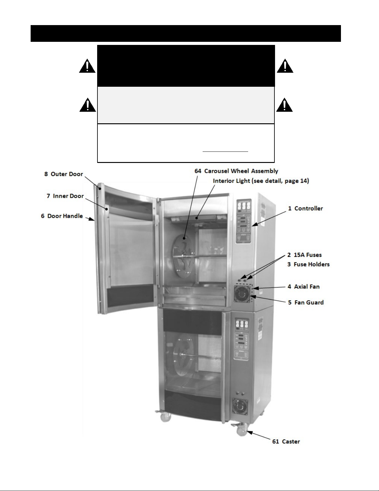
PARTS LIST (Part 1 of 5) W
N O T I C E
Service on this or any other LBC appliance must
be performed by qualified personnel. For an
approved service representative in your area,
visit our website at www.lbcbakery.com or call
our factory toll free at 1-888-722-5686.
C A U T I O N
USE OF ANY REPLACEMENT PARTS OTHER THAN
THOSE SUPPLIED BY LBC OR THEIR AUTHORIZED
DISTRIBUTORS CAN CAUSE BODILY INJURY TO
THE OPERATOR AND/OR DAMAGE TO THE
APPLIANCE AND WILL VOID ALL WARRANTIES.
BOTH HIGH AND LOW VOLTAGES ARE
PRESENT INSIDE OF THIS APPLIANCE WHEN
THE UNIT IS PLUGGED/WIRED INTO A LIVE
RECEPTACLE. BEFORE REPLACING ANY PARTS,
DISCONNECT THE UNIT FROM THE ELECTRIC
POWER SUPPLY.
W A R N I N G

13
PARTS LIST (Part 2 of 5) W

14
PARTS LIST (Part 3 of 5) W
Item No.
Part Description
Quantity
Part No.
Usage
1
Controller
1
40102-76
2
15A Fuse
2
30900-01
3
Fuse Holder
2
30901-02
4
Axial Fan
1
71500-33
5
Fan Guard
1
50201-11
6
Handle, Loading Door
1
180-781-1
5-Spit only
Handle, Loading Door
1
180-781-2
7-Spit only
7
Loading Door, Inner
1
71300-32
5-Spit only
Loading Door, Inner
1
71300-30
7-Spit only
8
Loading Door, Outer - Front
1
71300-33F
5-Spit, front door only
Loading Door, Outer - Rear
1
71300-33R
5-Spit, rear door only
Loading Door, Outer - Front
1
71300-31F
7-Spit, front door only
Loading Door, Outer - Rear
1
71300-31R
7-Spit, rear door only
20
Element, 2kW, 208 VAC
2
11090-37
5-Spit only
Element, 3kW, 208 VAC
2
11090-38
7-Spit, Washdown
Element, 3kW, 208 VAC
0 or 1
11090-39
7-Spit only
Element, 2kW, 208 VAC
2 or 3
11090-40
7-Spit 1 phase only
21
Capacitor, Fan (2.2μF)
2
40704-11
22
Thermocouple Temperature Sensor
1
41100-31
23
Relay
3
30701-05
24
Alarm
1
30802-07-1
25
Contactor
1
30700-17
26
Transformer
1
31400-26
27
Power Distribution Block
1
30500-07
28
High Limit Cutout
1
30401-33
29
Gearbox (90 Degrees, 1:90 Ratio)
1
30200-50
30
Gearbox (1:10 Ratio)
1
30200-49
31
Motor
1
30200-51

15
PARTS LIST (Part 4 of 5) W
Item No. Part Description Quantity Part No. Usage
32
Capacitor, Motor (4.0µF)
1
40704-10
40
Thermal Snap Disc (Relay Protection)
2
30301-05
41
Fan, Ceiling
2
71500-32
42
Fan Blade, Ceiling
2
180-205-1
50 Door Switch Assembly 1 or 2 180-767-2
51 Thermal Snap Disc (Lights) 2 30301-06 7-Spit only
52
Lamp Holder
4
31602-09
5-Spit only
53
Lamp, 1kW
2
31602-08
5-Spit only
54
Lamp Holder
4
31602-21
7-Spit only
55
Lamp, 500W
2
31603-87
7-Spit only
Optional Parts and Accessories
Item No. Part Description Quantity Part No. Usage
60
Stand with Casters
1
LST7
7-Spit only
61
Caster (Swivel with Brake)
4
72901-33
62
4” Adjustable Leg
4
72901-35
63
6” Adjustable Leg
4
72901-34
64
Carousel Assembly, Non-Stick Coating 1 180-768-1C 5-Spit only
Carousel Assembly, Stainless Steel
1
180-768-1
5-Spit only
Carousel Assembly, Non-Stick Coating
1
180-768-2C
7-Spit only
Carousel Assembly, Stainless Steel
1
180-768-2
7-Spit only
65
Angle Spit, Stainless Steel
5
LCR5-SV
5-Spit Only
Angle Spit, Non-Stick Coating
5
LCR5-SV-C
5-Spit Only
Angle Spit, Stainless Steel
7
LCR7-SV
7-Spit Only
Angle Spit, Non-Stick Coating
7
LCR7-SV-C
7-Spit Only
66
Fork Spit, Stainless Steel
5
LCR5-SF
5-Spit Only
Fork Spit, Non-Stick Coating
5
LCR7-SF-C
5-Spit Only
Fork Spit, Stainless Steel
7
LCR5-SF
7-Spit Only
Fork Spit, Non-Stick Coating
7
LCR7-SF-C
7-Spit Only
67
Basket, Stainless Steel
5
LCR5-SB
5-Spit Only
Basket, Non-Stick Coating
5
LCR5-SB-C
5-Spit Only
Basket, Stainless Steel
7
LCR7-SB
7-Spit Only
Basket, Non-Stick Coating
7
LCR7-SB-C
7-Spit Only
68
Restraint Kit (Safety Tether)
1
72609-51
69
Stacking Kit
1
Kit, Rotisserie 4
70
Hand Held Probe Kit
1
Kit, Rotisserie 5
16
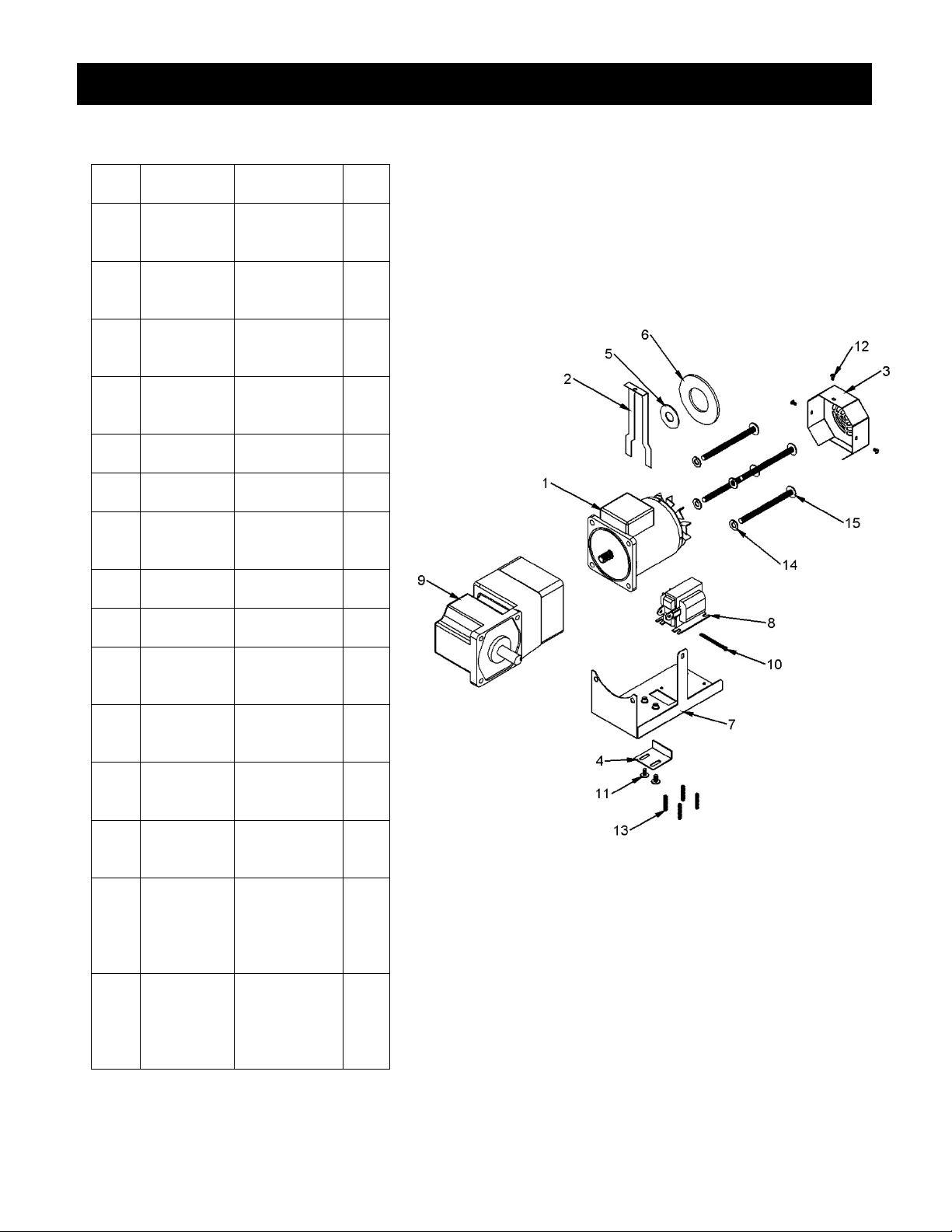
PARTS LIST (Part 5 of 5)W
Motor-Brake Assembly
ITEM
NO.
PART
NUMBER
DESCRIPTION QTY.
1 30200-51
(Capless)
Motor
(208VAC, 1ph,
1600rpm)
1
2 180-481
Lever, Motor
Brake
Solenoid
1
3 180-483
Fan Guard,
Motor Brake
Solenoid
1
4 180-484
Stop, Motor
Brake
Solenoid
1
5 180-485
Ring, Inner -
Teflon
1
6 70200-14
Washer,
Friction
1
7 180-480
Bracket,
Motor Brake
Solenoid
1
8
70403-04-
1-240
Solenoid,
Laminated
1
9 Gearbox
Gearbox -
Rotisserie
1
10
SCREW-PH-
SS-M3.5 x
0.6 x 50mm
PH SS SCREW
(M3.5 x 0.6
x 50mm)
1
11 Stock Part
Screw-Truss-
SS-M5 x
10mm
2
12 Screw -
M3.5
Screw - M3.5
(Drive
Motor Cap)
3
13 Stock Part
Screw-PH-SS-
DrillTip-Phil-
8-18, 1/2"
4
14 Stock Part
Washer -
M7.5 (Drive
Motor-to-
Gearbox
Attachment)
4
15 Screw -
M7.5
Screw - M7.5
(Drive
Motor-to-
Gearbox
Attachment)
4
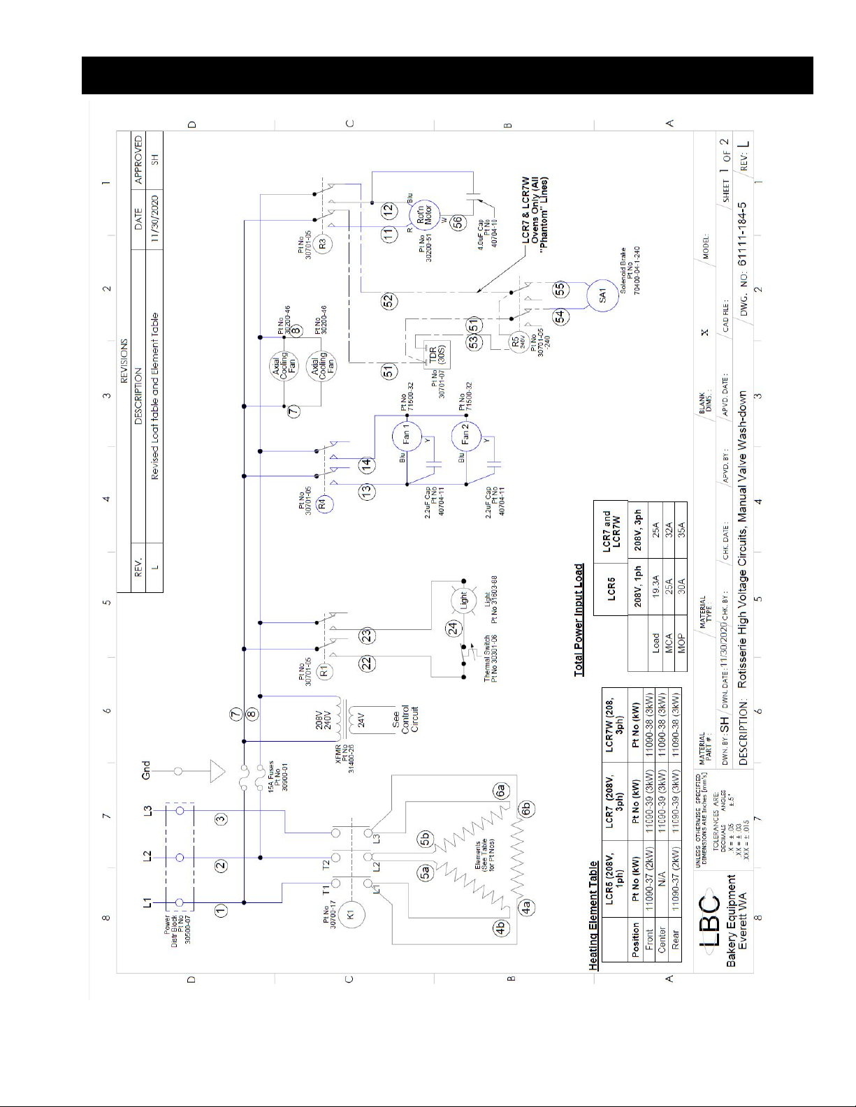
17
WIRING DIAGRAM (Part 1 of 2))

18
WIRING DIAGRAM (Part 2 of 2))n
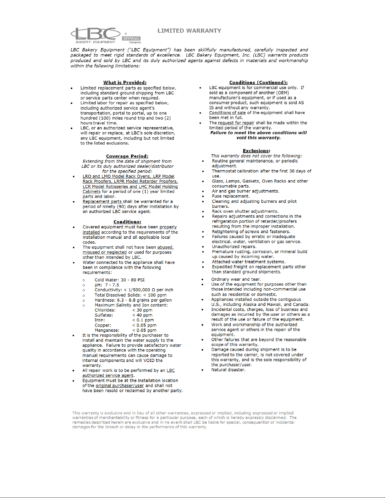
19
This manual suits for next models
1
Table of contents
Other sinmag Oven manuals


Popular Oven manuals by other brands


Kampa
Kampa Freedom operating manual

Siemens
Siemens HB778G3 1B Series User manual and installation instructions

KKT KOLBE
KKT KOLBE EU Series Service manual

Lino
Lino FL4 F8PTDS XS installation manual

cecotec
cecotec BOLERO HEXA SM406000 EDGE+ A+ instruction manual

Hotpoint
Hotpoint KSO89CX S operating instructions


