sinmag LBC LMO Max-E Manual

© Copyright 2017-2022 LBC Bakery Equipment, Inc. 1Rev 6/2022
MODELS LMO Max-E & LMO Max-G
ROTATING RACK OVEN
INSTALLATION and SERVICE MANUAL
GAS OVENS: POST IN A PROMINENT LOCATION, THE INSTRUCTIONS TO BE
FOLLOWED IN THE EVENT THE SMELL OF GAS IS DETECTED. THIS INFORMATION
SHALL BE OBTAINED FROM THE LOCAL GAS SUPPLIER.
RETAIN THIS MANUAL FOR FUTURE REFERENCE.
LBC BAKERY EQUIPMENT, INC.
6026 31st Ave NE
Tulalip, WA 98271, USA
Toll Free: 888-722-5686 (888-RACKOVN)
E-mail: sales@lbcbakery.com
www.lbcbakery.com

© Copyright 2017-2022 LBC Bakery Equipment, Inc. 2Rev 6/2022
READ FIRST (Part 1 of 2)
.
ALL OPERATORS OF THIS EQUIPMENT MUST BE OF LEGAL AGE TO OPERATE SUCH
EQUIPMENT AND MUST BE FAMILIAR WITH AND UNDERSTAND ALL CAUTION
LABELS.
READ, UNDERSTAND AND FOLLOW THE INSTRUCTIONS AND WARNINGS
CONTAINED IN THIS MANUAL. IT IS THE RESPONSIBILITY OF THE
OWNER/OPERATOR OF THIS APPLIANCE TO TRAIN, SUPERVISE AND AUTHORIZE
ANY PERSON DESIGNATED AS AN OPERATOR. ALL OPERATORS MUST READ AND
UNDERSTAND THIS MANUAL.
IMPORTANT
GAS OVENS: IN THE EVENT A GAS ODOR IS DETECTED, SHUT DOWN UNIT
AT MAIN SHUTOFF VALVE AND CONTACT YOUR LOCAL GAS COMPANY OR
GAS SUPPLIER FOR SERVICE.
FOR YOUR SAFETY
DO NOT STORE OR USE GASOLINE OR OTHER FLAMMABLE VAPORS OR
LIQUIDS IN THE VICINITY OF THIS OR ANY OTHER APPLIANCE.
IN THE EVENT OF A POWER FAILURE, DO NOT ATTEMPT TO OPERATE THIS
DEVICE.
KEEP AREA AROUND THE OVEN CLEAR OF COMBUSTIBLES.
GAS OVENS: DO NOT OBSTRUCT COMBUSTION AND VENTILATION OPENINGS
ON THE OVEN.
WIRING SCHEMATICS ARE LOCATED BEHIND THE APPLIANCE CONTROL PANEL IN
CONTROL COMPARTMENT.
WARNING
IMPROPER INSTALLATION, ADJUSTMENT, ALTERATION, SERVICE OR
MAINTENANCE CAN CAUSE PROPERTY DAMAGE, INJURY OR DEATH.
DO NOT OPERATE, CLEAN OR SERVICE THIS MACHINE BEFORE READING
THIS MANUAL AND UNDERSTANDING COMPLETELY THE SAFETY
INSTRUCTIONS FOUND HEREIN AND ON THE MACHINE’S LABELS.

© Copyright 2017-2022 LBC Bakery Equipment, Inc. 3Rev 6/2022
READ FIRST (Part 2 of 2) .
WARNING
THIS APPLIANCE IS EQUIPPED WITH A THREE-PRONG (GROUNDED) PLUG
FOR YOUR PROTECTION AGAINST SHOCK HAZARD. PLUG DIRECTLY INTO A
THREE-PRONG RECEPTACLE. DO NOT CUT OR REMOVE THE GROUNDING
PRONG FROM THIS PLUG.
WARNING
DISCONNECT FROM POWER SOURCE WHEN CLEANING AND/OR SERVICING
THIS MACHINE.
WARNING
NEVER ATTEMPT TO CLEAN THIS MACHINE WHILE IT IS HOT OR HEATING AS
RISK OF SERIOUS INJURY COULD RESULT.
WARNING
NEVER OPERATE THIS MACHINE WITH SAFETY COVERS OR INSPECTION
PLATES REMOVED OR WITH SAFETY SWITCHES INOPERATIVE.

© Copyright 2017-2022 LBC Bakery Equipment, Inc. 4Rev 6/2022
TABLE of CONTENTS .
Contents
READ FIRST ............................................................................................................................2
GAS OVENS: LIGHTING & SHUTDOWN ....................................................................................5
ELECTRIC OVENS: SPECIFICATIONS .........................................................................................6
GAS OVENS: SPECIFICATIONS.................................................................................................8
SAFETY CONSIDERATIONS ......................................................................................................9
RECEIVING ...........................................................................................................................10
INSTALLATION .....................................................................................................................11
GAS OVENS: NATURAL/PROPANE GAS CONVERSION............................................................15
STARTUP & INSPECTION.......................................................................................................17
PRESSURE PANEL SETTINGS ..................................................................................................20
CONTROL OPERATION & SETUP ............................................................................................21
DEFAULT PARAMETER SETTINGS ..........................................................................................24
ILLUSTRATED PARTS BREAKDOWN .......................................................................................28
ELECTRICAL SCHEMATICS......................................................................................................36
LBC LIMITED WARRANTY......................................................................................................41
© Copyright 2017-2022 LBC Bakery Equipment, Inc. 5Rev 6/2022
GAS OVENS: LIGHTING & SHUTDOWN
.
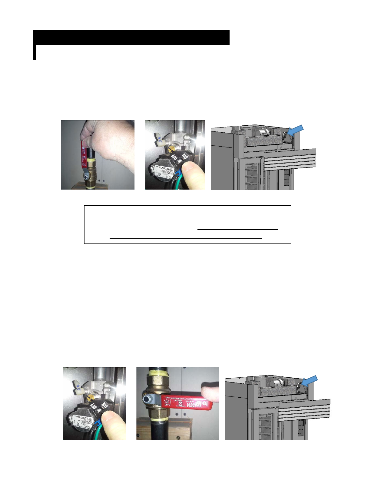
Lighting Instructions
After Long-Term Shutdown
1. Turn on the gas supply to the oven.
2. Open the gas valve access door located above the loading door.Switch the gas valve to
“ON.”
3. Keep the gas valve door open until the burner lights the first time.
WARNING
IF THE BURNER DOES NOT LIGHT, TURN OFF ALL GAS TO THE
OVEN FOR 5 MINUTES AND THEN BEGIN AT STEP 1.
Daily Use
1. Press the “Power” button to turn the oven on. Close the oven door.
2. Set the oven temperature to the desired operating temperature by pressing the up or down
arrow buttons next to the “Set Temperature” display.
Shutdown Instructions
Daily Use
Press the “Power” button to turn the oven off.
Long-Term Shutdown
Open the gas valve access door located above the loading door. Switch the gas valve to
“OFF” and turn off the gas supply to the oven.

© Copyright 2017-2022 LBC Bakery Equipment, Inc. 6Rev 6/2022
ELECTRIC OVENS: SPECIFICATIONS
Installation Requirements
•Oven ships fully assembled and will fit through a 36” door opening with removal of the oven door
assembly, valence and back panel. Check local codes to determine if the oven needs to be
installed under a hood.
•Clearance to Combustibles: 1” from back and sides, 18” from top
•Flooring: Appliance must be installed on a floor of noncombustible construction with
noncombustible flooring and surface finish and with no combustible material against the
underside thereof, or on noncombustible slabs or arches having no combustible material against
the underside. Such construction shall in all cases extend not less than 12” beyond the
equipment on all sides.
Water Quality Requirements
Utility Requirements

© Copyright 2017-2022 LBC Bakery Equipment, Inc. 7Rev 6/2022
100
85
55
0.7
(Control)
15
120V, 1ph, 60Hz
1/2"NPT,
cold water,
3 gpm
@ 45 psi min
3/4"NPT,
route to
air gap drain
Drain
Total kW
24.0
(Heaters)
208V, 3ph, 60Hz
240V, 3ph, 60Hz
480V, 3ph, 60Hz
Voltage, ph, Hz
85
75
35
15
MCA
MOP
Wate r

© Copyright 2017-2022 LBC Bakery Equipment, Inc. 8Rev 6/2022
GAS OVENS: SPECIFICATIONS
.
Installation Requirements
•Oven ships fully assembled and will fit through a 36” door opening with removal of the oven door
assembly, valence and back panel.
•Clearance to Combustibles: 1” from back and sides, 18” from top
•Flooring: Appliance must be installed on a floor of noncombustible construction with
noncombustible flooring and surface finish and with no combustible material against the underside
thereof, or on noncombustible slabs or arches having no combustible material against the
underside. Such construction shall in all cases extend not less than 12” beyond the equipment on
all sides.
Water Quality Requirements
Utility Requirements
Electric
120V, 15A, 60Hz
dedicated circuit;
NEMA 5-15R
receptical required
Gas
1/2"NPT connection,
125 kBTU/hr,
supply pressure =
5 - 14 inwc
Drain
Wate r
1/2"NPT,
cold water,
3 gph
@ 45 psi min
3/4"NPT,
route to
air gap drain

© Copyright 2017-2022 LBC Bakery Equipment, Inc. 9Rev 6/2022
SAFETY CONSIDERATIONS
.
Your LBC Bakery Equipment oven was manufactured to rigid standards. The oven is ETL listed
as a unit, and meets applicable safety standards.
A) The responsibility of the manufacturer is to supply suitable, comprehensive instructions
and recommendations for operation and maintenance of appliance.
B) All operations, maintenance and repair of oven must be performed by properly trained
and qualified personnel, and all operations, maintenance and repair must be performed
in a diligent manner. It is the responsibility of owner/operator to ensure proper training
and diligence of any person coming into contact with either oven or output (product,
exhaust or otherwise) of oven. It is the responsibility of owner/operator to ensure oven
is installed and operated in accordance with OSHA Standard 1910.263.
C) A regular periodic program of cleaning, inspection and maintenance must be established
and comprehensive maintenance records maintained. It is the sole responsibility of user
to establish, schedule and enforce frequency and scope of these programs in keeping
with recommended practice and with due consideration given to actual operating
conditions.
D) The units must be operated within limits which will not exceed working limits of any
component.

© Copyright 2017-2022 LBC Bakery Equipment, Inc. 10 Rev 6/2022
RECEIVING
..
CAUTION
THIS APPLIANCE WEIGHS MORE THAN 1000 LBS. FOR SAFE HANDLING, INSTALLER
SHOULD OBTAIN HELP AS NEEDED OR EMPLOY APPROPRIATE MATERIAL-HANDLING
EQUIPMENT (SUCH AS A FORKLIFT, DOLLY OR PALLET JACK) TO REMOVE THE UNIT
FROM ITS PACKING MATERIALS AND MOVE IT TO THE PLACE OF INSTALLATION.
NOTE: IF REQUIRED, YOU CAN REMOVE THE INNER RIGHT WALL COVER AND
REMOVE THE STEAMER MASS IN FOUR SECTIONS.
Upon receiving the appliance, immediately check for damage (both visible and concealed) and loss.
Visible damage must be noted on the freight bill at the time of delivery and signed by the carrier’s
agent. Concealed damage or loss means damage or loss which does not become apparent until the
merchandise has been uncrated. If concealed damage or loss is discovered upon unpacking, make
a written request for inspection by the carrier’s agent within 15 days of delivery. All packing
material should be kept for inspection. DO NOT return damaged merchandise to LBC Bakery
Equipment, Inc.; you must file your own claim with the carrier.

© Copyright 2017-2022 LBC Bakery Equipment, Inc. 11 Rev 6/2022
INSTALLATION
(Part 1 of 4) .
General Information
This appliance, when installed, must be electrically grounded in accordance with state and local codes,
or in the absence of local codes, with the National Electrical Code (ANSI/NFPA 70) or the Canadian
Electrical Code (CSA C22.2 No. 3, latest edition) as applicable.
The appliance requires some assembly by an authorized LBC trained service technician.
Do not enclose the top of the appliance to other construction. The top of the oven must be accessible
for service and must not be enclosed or covered. This clearance may be gained by removing baffles,
filters and other components, provided that removing the components does not create a hazard. Gas
Ovens: The top of the oven must also be open and have adequate air supply for combustion.
WARNING
THIS APPLIANCE MUST BE INSTALLED WITH A MINIMUM OF 1 INCH CLEARANCE FROM
SIDES AND BACK AND 18 INCHES CLEARANCE FROM THE TOP TO COMBUSTIBLE
SURFACES.
WARNING
THIS APPLIANCE MUST BE INSTALLED ON A NON-COMBUSTIBLE FLOOR EXTENDING
12 INCHES BEYOND THE APPLIANCE, WITH NON-COMBUSTIBLE CONSTRUCTION
UNDER THE FLOOR.
General Information – Gas Ovens
This appliance must be installed under a ventilation hood.
This appliance must be connected to a gas shutoff valve in accordance with CSA 9.1-M97 – ANSI Z21.15-
1997 and Addenda CGA 9.1 a-2001 – Z21.15a-2001, Manually Operated Gas Valves for Appliance,
Appliance Connector Valves and End Valves.
The installation of this appliance must conform with local codes, or in the absence of local codes, with
the National Fuel Gas Code (ANSI Z223.1/NFPA 54) or the Natural Gas and Propane Installation Code
(CSA B149.1) as applicable, including:
•The appliance and its individual shutoff valve must be disconnected from the gas supply piping
system during any pressure testing of that system at test pressures in excess of 1/2 psi.
•The appliance must be isolated from the gas supply piping system by closing its individual shutoff
valve during any pressure testing of the gas supply piping system at test pressures equal to or less
than 1/2 psi.
This appliance is configured to operate on natural gas or propane gas. A gas conversion kit is available
for this appliance. See the name plate on the appliance to determine if the appliance is
configured for natural gas or propane gas. For conversion instructions, see the “Natural/Propane Gas
Conversion” section of this manual.

© Copyright 2017-2022 LBC Bakery Equipment, Inc. 12 Rev 6/2022
INSTALLATION (Part 2 of 4) .
Uncrating and Moving
1. Move oven to area where it is to be installed. NOTE: If the oven is to be moved through a 36”
door, see section directly below.
2. Disassemble crate. Use caution to avoid damage to oven with pry bars or nail removers.
3. Remove plastic wrap and padding from outside of oven. Remove components from inside of the
oven.
4. Use a fork lift to lift oven off of shipping skid. Slide forks under outer wall of oven. Do not lift at
middle of oven floor. As an alternate method, oven is equipped with lifting eyes on top. Connect
a chain or lifting strap capable of lifting 2000 pounds to the two lifting eyes to raise oven off of
skid. Place oven on floor close to its final location.
Moving the Oven through a 36” Doorway (contact LBC for detailed instructions)
1. Disassemble crate. Use caution to avoid damage to oven with pry bars or nail removers. Remove
plastic wrap and padding from outside of oven. Remove components from inside of the oven.
2. Remove top access cover of oven. Remove four internal hex-head screws between the slats of
forward valance, then tilt access cover forward and lift it out.
3. Open loading doors. Remove door latch cam follower.
4. Remove valance assembly by removing the four screws attaching it to side trim. Slide the valance
forward.
5. Remove top trim.
6. Remove screw attaching magnetic reed door switch to front of oven above control. Allow switch
to hang in position.
7. Remove door assembly.
WARNING
DOOR ASSEMBLY IS HEAVY. USE EVERY PRECAUTION TO AVOID
PINCHING FINGERS. USE ASSISTANCE TO MOVE DOOR ASSEMBLY.
a. Remove the two screws attaching the lower door hinge to the front of the oven on both
doors.
b. Remove the screws connecting the oven floor to the threshold.
c. Remove the four screws connecting the door mechanism to the front of the oven at the top
of the door assembly. Use caution to keep fingers out of pinch points.
d. Carefully move door assembly away from front of oven without tilting it. Wrap door
assembly with stretch wrap, rope or tape to keep doors from opening or moving.
e. Prop door in a safe location. Make sure it will not fall.
8. Gas Ovens: Remove two screws from gas inlet pipe bracket at back of oven. Push gas pipe
forward so it clears door opening.
9. Remove power cord and rear panel from oven.
10. Move the oven through doorway sideways. NOTE 1: Oven weighs more than 1000 lb. If required,
you can remove inner right wall cover and remove steamer mass in four sections. NOTE 2: Oven
floor can be removed if necessary to lift oven from the inside.
11. Replace all components removed in steps 1 through 10.

© Copyright 2017-2022 LBC Bakery Equipment, Inc. 13 Rev 6/2022
INSTALLATION (Part 3 of 4) .
Setting the Oven in Place
1. Locate the oven in final location. Refer to “Specifications” section of this manual, “Installation
Requirements” notes, for clearance to combustibles specifications.
2. Confirm floor is non-combustible and is supported by non-combustible construction.
3. Confirm there are no buried electrical wires or conduit, pipes or other utilities beneath oven.
4. Level oven by installing stainless steel shims under four corners as required. NOTE: Keep oven
directly on floor if possible.
Electrical Connections
Both electric and gas ovens require connection to 120 VAC, 15 amp dedicated service. Gas ovens are
shipped with cord and plug. Do not tamper with or modify plug or ground connection on cord.
Electrical Connections – Electric Ovens
Oven electrical connection for heat circuit is located in electrical box in control compartment. A 1”
conduit raceway is provided to a junction box in lower right rear of oven.
Gas Supply Specifications – Gas Ovens
1. Confirm available gas type is same as that stated on name plate of oven.
2. Confirm gas supply is regulated. Maximum pressure is not to exceed 14 inwc or 1/2 psi. Confirm
supply is adequate for 125 kBTU per hour. Gas supply pipe should not be less than 3/4” NPT.
3. Confirm that an approved gas shutoff valve is installed before the appliance.
4. Connect gas supply to oven using an approved 3/4” gas supply connector. Use only sealant
approved for gas connections.
60 Hz
© Copyright 2017-2022 LBC Bakery Equipment, Inc. 14 Rev 6/2022
INSTALLATION (Part 4 of 4) .
Water Connection
This appliance must be installed with adequate backflow prevention in accordance with applicable
federal, state and local codes.
1. Confirm availability of cold water near connection point on top of oven.
2. Confirm that there is a water shutoff valve within reach of connection point.
3. If necessary, install and connect a water treatment device at water supply connection
downstream from water shutoff valve. An LBC water filtration assembly (no. 72610-48) with
carbon block and scale stick cartridges is strongly recommended.
4. Connect water supply to the water solenoid valve on the top of the oven using an approved water
connector.
Drain Connection
1. The drain fitting is 3/4” NPTM, located at the right rear corner of the oven.
2. Confirm that an air gap drain is available within 10 feet of the drain connection point.
3. Connect the drain line to the drain fitting using a hose or pipe suitable for connection to a drain
and capable of handling 210oF water. The drain line should be 3/4” or larger and must slope
1/4 inch per foot to the drain.
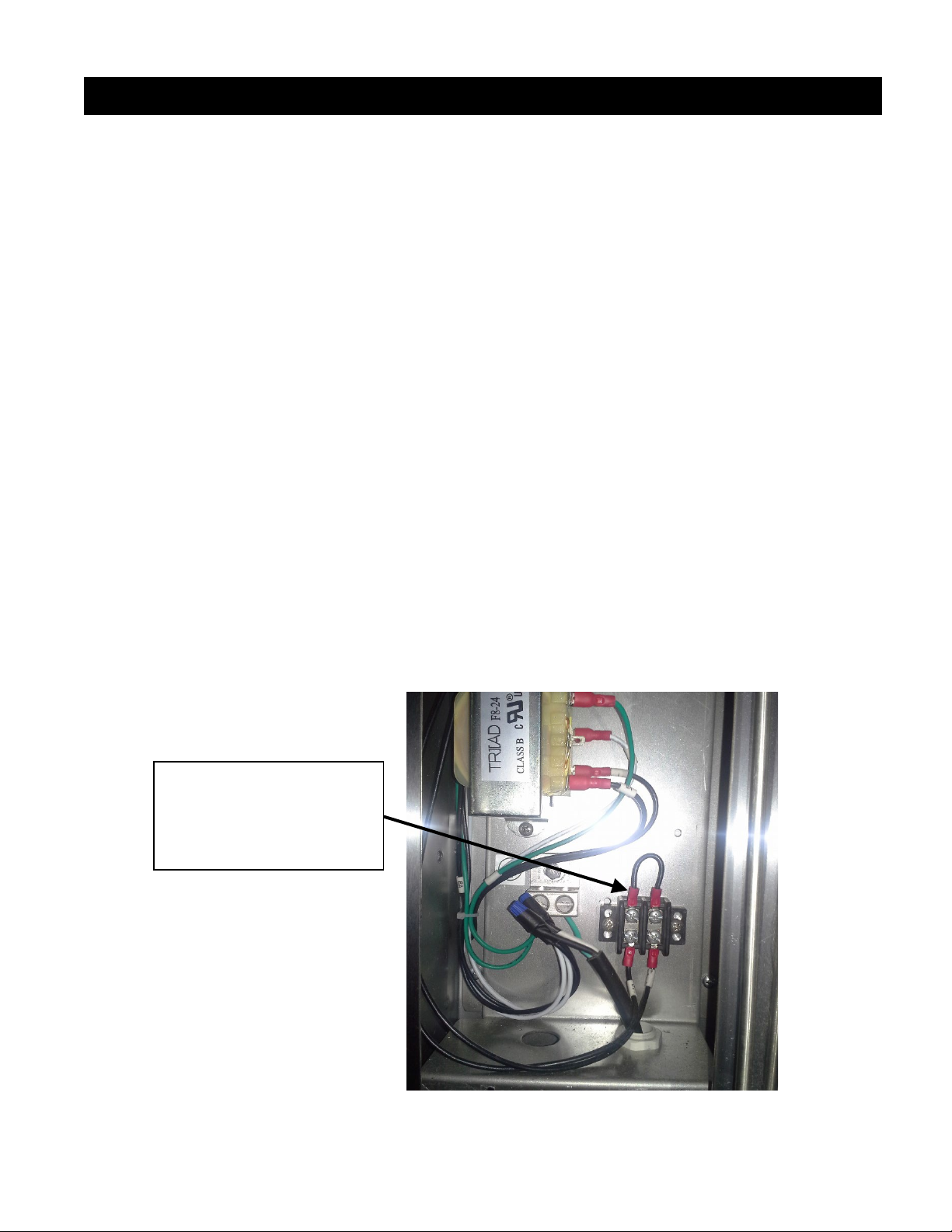
Hood Interface
NOTE 1: Some locations require that the heat output of the oven be interlocked with the operation
of the ventilation hood system. The heat circuit interlock connection is located at the electrical
connection point in the front of the oven. To interlock the oven heat circuit to the hood, remove the
jumper at wires 9 and 10 and connect to a dry contact connection. The interlock device should simply
interrupt the 24 volts between wires 9 and 10. NOTE 2: The Commonwealth of Massachusetts
requires that the flow of gas to the oven is interrupted when the hood ventilator is not operating.
Hood Ventilator Interlock
Connect point. Remove
This jumper and connect
The interlock here.
© Copyright 2017-2022 LBC Bakery Equipment, Inc. 15 Rev 6/2022
GAS OVENS: NATURAL/PROPANE GAS CONVERSION
.
(Part 1 of 2).
This oven was shipped configured to operate on either natural gas or propane gas. Consult
the data plate to determine which fuel the oven is configured for.
The oven can be reconfigured for either natural gas or propane gas.
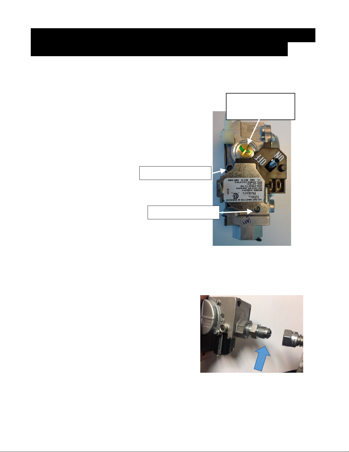
Gas Pressure
Both natural gas and propane
gas configurations have a
manifold pressure setting of
3.5 inwc.Do not change
pressure regulator spring
when making conversion.
Always confirm gas pressure
once conversion is complete.
To check manifold pressure,
loosen set screw in manifold
pressure tap. Install 1/4”
hose from manometer on
pressure tap. Read manifold
pressure with burner on.
Tighten set screw when
manometer hose is removed.
Burner Orifices and Exhaust Restrictor Plate
The orifices for each burner are different for natural gas and propane gas. The firing rate
is 125,000 BTU/hr.
Natural Gas orifice is drilled and marked #49 and the restrictor plate is marked “NG”.
Propane Gas orifice is drilled and marked #53 and the restrictor plate is marked “LP”.
To Change Orifices
1. Turn off the gas supply to the oven at the wall.
2. Remove the burner cover from the top of the
oven.
3. Disconnect the electrical wires at the front of
the burner for the hot surface ignition and the
flame sensor.
4. Disconnect the wires from the gas valve.
5. Disconnect the flexible gas line at the union
located at the gas valve (see illustration).
Manifold pressure
adjustment (cap
installed)
Supply pressure tap
Manifold pressure tap
Disconnect
gas Line here.

© Copyright 2017-2022 LBC Bakery Equipment, Inc. 16 Rev 6/2022
GAS OVENS: NATURAL/PROPANE GAS CONVERSION .
(Part 2 of 2).
6. Carefully pull burner assembly up and out of top of oven. Use caution to avoid damaging
the hot-surface ignitor and flame sensor on the burner.
7. Remove burners from
burner assembly.
8. Remove and replace gas
orifices. Clean any
sealant or seal tape from
orifice threads and
manifold. Use only
sealant approved for fuel
gas.
9. Reassemble burner
assembly.
10. Replace burner assembly
in oven. Reconnect gas line, hot surface igniter wires and flame sensor wire.
11. Loosen the screws mounting the draft
inducer to the exhaust collector box.
Remove the top screw. Remove and
replace the restrictor plate. Re-install
the top screw and tighten all
mounting screws. (Note: The hole in
the restrictor plate must align with the
center of the draft inducer inlet.)
12. Replace burner cover on top of oven.
13. Attach appropriate label provided on data plate to indicate conversion of burner.
14. Turn on gas supply to oven. Check for leaks.
15. Light oven. Refer to “Lighting & Shutdown” section of this manual.
THIS OVEN IS
CONFIGURED FOR
NATURAL GAS
THIS OVEN IS
CONFIGURED FOR
PROPANE GAS
OR

© Copyright 2017-2022 LBC Bakery Equipment, Inc. 17 Rev 6/2022
STARTUP & INSPECTION
.
LMO-Max START-UP FORM: This form MUST BE SIGNED & RETURNED to LBC via Email to
service@lbcbakery.com or FAX 425-642-8310, in order for the Customers Warranty to take effect
LMO-Max Rack Oven Inspection Procedure
Specifics Serial Number ________________________________________
Model Number ________________________________________
Location Name ________________________________________
Address ________________________________________
City, State ________________________________________
Photos: (Attach the following Photos to this inspection):
Any visible damage _____________
Data plate _____________
Power Connection in the oven connection box _____________
Water Supply (filter, RO system or softener) _____________
Gas Supply Pipe _____________
Location Details: AS FOUND
If No,
CORRECTED?
Oven on Non-combustible floor? Y_____ N_____ _____
Is the oven Level? Y_____ N_____ _____
Oven Type:
Gas Nat____ Prop.____
Electric (Voltage):
208 Volts _______ 240 Volts ________ 480 Volts ________
Install Quality:
Supply voltages: Dedicated 120 VAC, 15Amp Max Rating Y_____ N_____ _____
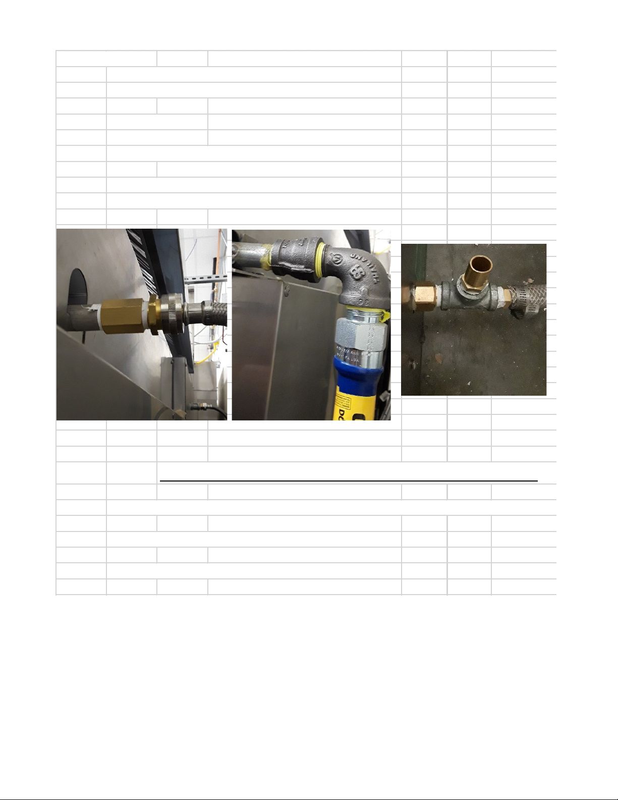
Water Connection: No leaks? (Fig. 1) Y_____ N_____ _____
Gas Connection: No leaks? (Fig. 2) Y_____ N_____ _____
Drain Connection: Properly connected and
to an air-gap drain? (Fig. 3) Y_____ N_____ _____
If hood interlock is required; confirm proper connection and
hood power switch is properly labeled Y_____ N_____ _____
Functional Check: Turn on power to oven.
Press power button on control. Unit turns on? Y_____ N_____ _____
Interior lights turn on when the door is opened? Y_____ N_____ _____
Roll in a rack and close loading door. Confirm:
Blower motor starts? (Audible) Y_____ N_____ _____
Rack starts to rotate. Wheels off the ground? Y_____ N_____ _____

© Copyright 2017-2022 LBC Bakery Equipment, Inc. 18 Rev 6/2022
Burner test:
Set to 125° F. (Temp starts to rise within a minute?
Y_____ N_____ _____
(If temp does not start to rise, Call LBC)
Supply side gas pressure when burner is running?
_____ WC _____
(If less than 5" and greater than 14", Call LBC)
Set to 300° F. Minutes to go from 150° to 250° F? _____ Mins
Combustion Test:
Set to 350° F. Wait one minute:
Check Carbon Monoxide for 1 minute. CO__________PPM
(If greater than 75%, Call LBC)
Take Photo of CO Measurement.
Check sensor VOLTAGE at test point:
____________VAC
(If Voltage is not between 3-6 VDC, call LBC)
Steam Test: Can you hear hear the solenoid open and water
spraying? (Audible) Y_____ N_____ _____
Rack Stopping Position (Hot Oven):
Carrier Stops at the door when door is opened? Y_____ N_____ _____
Check Air-Gap settings on pressure panel.
Refer to settings in manual. Y_____ N_____ _____
© Copyright 2017-2022 LBC Bakery Equipment, Inc. 19 Rev 6/2022
Final Inspection:
Loading doors open/close freely past 90° without obstruction
Y_____ N_____ _____
Doors open 1/2" to 1" before motor and rack Stops? Y_____ N_____ _____
Gas is on? Y_____ N_____ _____
Electrical Is on? Y_____ N_____ _____
Water is on? Y_____ N_____ _____
Gaskets: Installed and seated correctly? Y_____ N_____ _____
No cracks or missing pieces? Y_____ N_____ _____
All screws and electrical are tight? (If not, tighten down firm
Y_____ N_____ _____
All plumbing connections are tight and do not leak. Y_____ N_____ _____
Fig. 1 Fig. 2 Fig.3
FOR TECHNICAL SUPPORT, CALL LBC: 888-722-5686 x1
Name: __________________________________________ Company: _____________________________
Signature:
____________________________________________________
Date ____________________________________________________

© Copyright 2017-2022 LBC Bakery Equipment, Inc. 20 Rev 6/2022
PRESSURE PANEL SETTINGS
.
Adjust gap between shutter side of air opening adjacent to adjusting screw.
Left Side
Right Side
11/32
9mm
0.35
0.35
9mm
11/32
13/32
10mm
0.41
0.44
11mm
7/16
13/32
10mm
0.41
0.44
11mm
7/16
11/32
9mm
0.35
0.35
9mm
11/32
5/16
8mm
0.32
0.32
8mm
5/16
5/16
8mm
0.32
0.29
7mm
9/32
5/16
8mm
0.32
0.29
7mm
9/32
5/16
8mm
0.32
0.32
8mm
5/16
11/32
9mm
0.35
0.32
8mm
5/16
9/32
7mm
0.29
0.32
8mm
5/16
This manual suits for next models
1
Table of contents
Other sinmag Oven manuals


Popular Oven manuals by other brands


Siemens
Siemens CM833GB 1A Series User manual and installation instructions

Blanco
Blanco BOSE902 Instructions for the use and care and installation

Siemens
Siemens HB.78BB.6 User manual and installation instructions

Teka
Teka HLF 924 user manual

Kenmore
Kenmore 790.4028* Use and care guide

AEG
AEG COMPETENCE 5210 BU Operating and installation instructions


