Sinovision SPEED DOME User manual

User
manual
Thank
You
for Choosing a Mini SPEED
DOME
Camera Product!
All
of
our products are backed by a conditional service warranty covering all hardware
for
12 months from the
date
of
purchase.
lntroduction
This manual is written
for
SPEED DOME camera and was accurate at the
time
it was compteted. However,
because
of
our ongoing effort to canstantly improve
our
products, additional features and functions may have
been added since that time and on-screen displays may change. Throughout the manual we have highlighted
warnings and other important informatlon that wíll assist
you
in operating your new system in a safe and
trouble-free manner. Please take the time
toread
and follow ali instructions and
pay
attention to alerts as shown
below:
FEATURES & SPECIFICATIONS
Product
Features
Your camera offers the following features:
• High quality video uslng AHD 1/3" Megapixel image sensor,digital signal
processorto
produce 720P,960P,
1080P High resolution.
• Weatherproof 1P66 Rating
• RS485 control.
• 128 preset points.
• 360º continuous horizontal rotation with 90º vertical rnovement.
• Low-noise camera rotation motor.
• Memory function retains settings in case
of
power loss.
SPEED DOME
Module
Features
• Horizontal scanning: 360º rotation
• Rotation/tilt speed: 13º/second
• 128 preset positlons -80 preset positions and 48 speciat function settings.
11
Cruise route can save 16
preset
positíons with each position pausing for 5-60 seconds.
• Preset positions speed: 50º/second
• SPEED OOMEZ scanning precision ±0.5º
• FuUy-functiona1 built-in decoder -all data is saved inside
of
the module to retaln settings in case
of
power loss.
• Decoder's all-in-one integrated design ensures high rellability.
• Camera can be controlled with
an
Speed Domeional keyboard
because
of
location, position, etc. To access the panel, one
must
remove the clear dome by first twisting the
collar around the dome counterclockwlse and then removing the plastic dome to the camera. Take
careto
not
scratch the clear dome while removing it. The circuit board on which the DIP switches are mounted is visible
below the camera
in
the bottom plcture.
DIP switches are binary -meaning that
they
are either On n
")
or
Off
(UO").
Oifferent combinations
of
ones and
zeroes on the board produce different settings.
SETTING CAMERA
AOORESS
1 1 1 ooo
000100
SETTING PROTOCOL
Pelco-P/D(Auto recognition)
CONNECTING THE
CAMERA
Before you can operate the camera, you must connect it to a system which can support SPEED DOMEZ
operations. There are three sets
of
connectors -power, video and the bare control wires. This latter connection
is covered on the
neld:
page.
We
recommend connecting the camera (at least temporarlly)
to
the DVR to
test
your settlngs and connections befare mounting it in its final location.
POWER ANO VIDEO CONNECTION
STEP 1. Connect the BNC and power leads from the camera to the matching connectors on a video/power
SPEED DOME
Dome
Camera
Specifications
lmage Sensor 1.0/1.3/2.0Megapixel Sensor AHD Solution
Signa! System NTSC or PAL models
Le
ns
4MM/6MM MP
füced
lens
OR12XZoomlens
Scanning
2:1
lnterlace
Sync. System Interna[
Horizontal System 720P/960P/1080P
Effective Pixels (HxV) PAL/NTSC;12so•720.12so·sso,
1920~1
oao
Shutter Speed NTSC=1/60,.....1!100,000 sec
PAL=1150-
1/100,000 sec.
Minimum
rnumination 0.01 Lux
S/N Ratio > 52dB
Gamma 0.45
White Balance Auto
BLC Auto
AGC Alrlo
Video Output 1
.OV
P-P,750
BNC 1
Input Current 12V 1000mA {12V
2A
for
IR PT)
Operating Temp 14gF to
122ºF
(·1
OºC
to 50º) (relative 1
humidity: up to
95%)
IR
Dist-ance 30Meter{for IR
$peed
Dome Optional)
Storage Temp
-22"F
to 158ºF (-30gC to 70ºC)
Color White
Address Range 1-64
Control Protocol Peleo-O and Pelco-P
Baud Rate 1200b/2400b/4800b/9600b
SETTING
BAUD
RATE ANO ADDRESS
Uníike conventional security cameras,
SPEED
OOMEZ cameras require an address
anda
connection speed to
be set in order
for
them to properly operate. The default settings for this camera are an address
of
"1"
anda
baud rate
of
2400 and uSing the Peleo-O protocol. tf you are connecting the camera in accorda,nce to the
instructions included with the bundle, you should
not
have to change any
of
its settings. In either case,
if
you are
only using a single SPEED DOMEZ camera you generally do not have to make any changes and you may
proceed to the next section. Please
consult your DVR's manual
for
required settings.
lf
you need to change your camera's settings, they are made
using a DIP (dual in-line package) switch panel located within the camera itself.
In
general,
it
is easier to do this
befare connecting the camera, but in sorne cases, you may need to change settlngs while the camera is
connected to the DVR,
In
this case, please make a temporary connection by following the procedures laid out in
the next section.
Connecting
the
Camera.
Please be advised that adjusting these settings after füe camera
is
bundle package).
STEP
2,
Connect the power lead on the other end
of
the video/power cable to a power adaSpeed Domeer
or
power d!stribution panel.
Make
certain
that
the
power
supply
is
rated
for
12
volts
and
800mA
to
1.SA.
STEP 3. Connect the BNC connector on that same end
of
the cable to a Video In port on the
back
of the DVR.
SPEED OOMEZ CONTROL CONNECTION
In
addition to connecting the
power
and video leads to the camera, you must also connect the two control wire
leads to the RS485 ports in the alarm block on the back
of
the DVR. These blocks can vary in layout as shown
below, but the ports used by your OVR are generally labelled "RS485n,
~RS422",
"SPEED DOMEZ" or "P/Z".
As
seen in the picture on the upper right, the wire leads frorn the camera are two different colors and are labeUed.
They are also pre-installed into a block which p!ugs into a matching receSpeed Domeacle on the extension cable.
The control wire leads
at
the other end
of
the extension cable must be inserted into the ports
on
the back of the
DVR. In the case
ofthe
RS485 ports being marked
as
positive (+) and negative (-), the wire designated RS485A
(_orange
tip)
is the positive lead while the wire marked RS4858
(yellow
tip)
is to go into the negative port. Your
camera comes wíth a connector SPEED DOMEZ blocks elther have small screws to above each port to secure
the wire or require a tock above the port to be depressed with an object llke a
smaU
screw
driver in order to fully
insert the wire.
In
the latter, when the
lock
is
released,
an
interna! clamp will keep the wire firmly secured in the
port.
lf
the wire can easily be removed from the port, then lt
isn't
secure and you can experience control
difficulties until
it
is properly attached. Space permitting, mu!tipie SPEED
DOMEZ
cameras may be connected to
the same ports. They will each require a different address which is set up using the DIP switches as covered in
the previous section.
example
of
SPEED DOMEZ blocl<s
usíng
spríng·loaded
locks.
To connect your camera to the DVR
overa
distance, you wilf need to use both a video/power cable
anda
pair
of
24-gauge wires to connect to the alarm block.
lf
your camera carne as part of a package, these wires may be
included separately
or
as part
of
the video and
power
cable.
Once you have made your connections, you will need to make settings on the DVR in order to control it. You will
need to consutt
your
DVR's
manual for this procedure
When installing your camera, it is important to setect a proper site
not
onfy for field view, but for other
considerations as wefl:
Olstance
from
viewing/recording
device.
The further the camera is from the DVR or monitor, the higher the
chances of signal degradation.
Oo
not
place
near
high
voltage
wires
or
other
sources
of
electrical
interference.
Electricat interference will
degrade the qua!ity
ofthe
signa!.
Place
camera
out
of
reach
to
avoid
damage.
Avoid
direct
exposure
to
weather.
Do
not place the camera
where rain or snow will hit the
1ens
directly nor should the camera be placed
so
that the sun or bright light shines
directly into the
1ens.
Your camera is weatherproof, but it will not work when submerged
in
water. Ensure that
al!
power and video connections are not directly exposed to water and are protected from the elements.
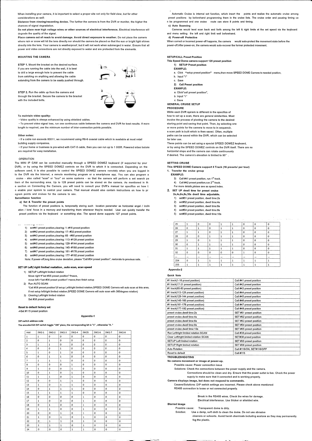
MOUNTING THE CAMERA
STEP 1. Mount the bracket
on
the desired surface.
1f
you are running the cable into the wall, it is best
to
drill a
Jarge
enough hote to prevent the cable
from catching
on
anything and allowing the cable
extending from the camera to be easily pushed through.
STEP 2. Run the cable
up
from the camera and
through the bracket. Secure the camera
to
the bracket
with the included bolts.
To
maintain
video
quality:
•Video
quality is always enhanced by using shielded cables.
\~+
iii)
•To
prevent video signa! loss,
run
one continuous cable between the camera and DVR for best results.
lf
more
length is required, use the mínimum number of inter·connection points possible.
Other
notes:
•
lf
a cable run exceeds 80011, we recommend using R6·6 coaxial cable whlch is available at most retail
building supp!y companies.
•
lf
your home or business is pre·wired with CAT
.5
cable, then you can run up to 1
OOOfl.
Powered video baluns
are
required for easy instaflation.
OPERATION
The MINI
IP
CAM
can
be controlled manua!ly through a SPEED DOMEZ keyboard (if supported by your
DVR), or by using the SPEED DOMEZ controls
on
the DVR to which it is connected. Depending
on
the
software used, it is also possible to control the SPEED DOMEZ camera remotely when you are logged
in
to the DVR via the Internet, a remete monitoring program or a smartphone app. You can also program a
cruise • also called "sean" or
~tour"
on
sorne systems · so that the camera will perform a set search
pa
ttern of the surrounding area. Up to 128 preset points can be stored
on
the camera. As mentioned in
th
e section
on
Connecting the Camera, you
wm
need to consult your DVR's manual tor specifics
on
how t
o enable your system to control your camera. That manual shoutd also contain instructions
on
how to pr
ogram points and cruises for the camera to use.
Surveillance function
a)
Set & Transfer the preset points
The function of preset positions
is,
temporarily storing such location parameter
as
horizontal angel I inclin
ation
I lens' focus
in
a memory and transferring them whenever they're needed. User
can
quickly transfer
the
preset positions
via
the keyboard
or
something
e!se.
The speed dome supports 127 preset points.
1)
set#41
preset position,clearing:
1·..#16
preset position
2) set#42 preset position,clearing:
17-#32
preset position
3)
set#43 preset position,clearing:
65
-...#80
preset position
4)
set#44 preset position,clearing: 113·..#128 preset position
5)
set#45 preset position,clearing: 129-..#144 preset position
6)
set#46 preset position,clearing: 145·..#160 preset position
7)
set#47 preset posilion,clearing: 161--#176 preset position
8) set#48 preset position,cfearing: 177·-#192 preset position
Note:
lf
power·off,long time cruise devialion, p!ease "Call #34 preset position", restorate to previous sate.
SET
UP
Left/right
limited
roatation,
auto
sean,
sean
speed
1) SETUP Left/right limited rotation
Move
right~"set
#35 preset
position"~save,
move
left·>nset #36 preset position"·>save.then finish setup
2)
Run
AUTO SCAN
"Call #38 preset position"(if setup Left/right limited rotation,SPEED DOME Camera wlll
auto
sean
at
this
are
a,
lf
not setup left/rightlimited rotation,SPEED DOME Camera will auto
sean
with 360degree rotation)
3)
Clearing Left/right limited rotation
Set #38 preset position
R:eset
to
defaultfactory set
->Set #115 preset position
DIP
switch
address
code
Appendix-1
The
encoded
bit
OIP
switch toggle "ON" place,
the
corresponding
bit
is
"1",
otherwise
"O."
Add SW2-1 SW2-2 SW2-3 SW2-4 SW2S SW2-6 SW2-7
1 1 o o o o o o
2 o 1 o o o o o
3 1 1 o o o o o
4 o o 1 o o o o
5 1 o 1 o o o o
6 o 1 1 o o o o
7 1 1 1 o o o o
8 o o o 1 o o o
9 1 o o 1 o o o
10
o l o 1 o o o
11 1 1 o 1 o o o
12 o o 1 l o o o
13
1 o 1 1 o o o
14 o 1 l 1 o o o
15 l 1 1 l o o o
16 o o o o 1 o o
--------·
17 l o o o 1 o o
18 o 1 o o 1 o o
19
1 1 o o l o o
20 o o 1 o 1 o o
21 1 o l o l o o
22 o 1 1 o 1 o o
23 1 l l o 1 o o
24 o o o
·-··---
_:__
_____
~--
·-~·---
o
------
SW2-8
o
o.
o
o
o
o
o
o
o
o
o
o
o
o
o
o
o
o
o
o
o
o
o
o
Automatic Cruise
is
interna[ set function, which insert the polnts and realize the automatic cruise among
preset positlons by beforehand programming them
in
the
cruise lists.
The
cruise order
and
pausing timing
ca
n
be
programmed
and
one cruise route can store 8 points
and
timing.
e)
Auto
Scanning
Cameras would level
sean
back
and
forth among
the
left & r!ght limits
at
the set speed
via
the keyboard
and
menu
setting
the
left
and
right limit well beforehand.
d) Power-off Protective
When corrector incorrect power·off happens, the camera would auto·protect
the
movement state befare the
power·off.Afler power·on, the camera
wou1d
auto·recover the former protected movement.
SETUPICALL Pres.et Position
This Speed Dome camera
support
128 preset
position
1) SETUP Preset
position
EXAMPLE:
a.
Click "setup preset position" menu,then move SPEED DOME Camera to needed position,
b.
Input
"1"
c.
Save
2) Cal! Preset position
EXAMPLE:
a:
Click"ca!I preset position",
b:
Input "1"
e:
Save
GENERAL CRUISE SETUP
PROCEOURE
Whi!e each DVR system is different
in
the specifics of
how
to
set up a sean, there are general similarities. Most
involve the process of pivoting the camera to the desired
starting point and saving that point. Then, by selecting one
or more points for the camera to move to
in
sequenc'e,
a sean path is built which is then saved. Otten, multiple
paths can be saved within the DVR, which can be selected
for later use.
These points can be set using a speclal SPEED DOMEZ keyboard,
or by using the SPEED DOMEZ controls
on
the DVR itself. There
are
no
horizontal stops and the camera
can
rotate continuously
if
desired. The camera's elevation is limited to 90º .
SETTING CRUISE
Tflis SPEED DOME
Camera
support
8
Track
(16
presets/
per
tour)
1.
Transfer the cruise
group
EXAMPLE:
3)
Call
#41
preset position,
run
1•t
track.
4) Call #42 preset position,run
2"d
track.
For more details,p!e'ase
see
as
speed index.
2. SET
UP
dW-ell
time
for
preset cruise
2s,4s,6s,8s,10s
dwell
time
adjustable.
1)
set#51
preset position,
dwe!I
time:2s
2)
set#52 preset position, dwetl time:4s
3)
set#53 preset position, dwell time:Ss
4) set#54 preset position, dwell time:8s
5)
set#55 preset position, dwell time:1
Os
25 1 o o 1
26 o 1 o 1
27
1 1 o 1
28 o o 1 1
29 l o 1 1
30
o 1 1 1
31 1 l 1 1
32
o o o o
'"
254
o 1 1 l
255 l l 1 1
Appendix-2
Quick Note
#1
track(1~16
preset position)
#1
track(17-31 preset position)
#1
track{65-80 preset position)
#1
track(113·128 preset position)
#1
track{129-144 preset position)
#1
track(145-160 preset position)
#1
track(161·176 preset position)
#1
track(177~192
preset position)
preset cruise,dwell time:2s
preset cruise,dwell time:4s
preset cruise,dwell time:6s
preset cruise,dwell time:8s
preset cruise,dwell
time:1
Os
Run
Left/right fimited rotation SCAN
Clear LefVright limited rotation SCAN
SETUP Left
Jimited
rotation
SETUP Right limited rotation
Auto Rotation
Reset
to
default
TROUBLESHOOTING
No
camera
movement
or
image
at
power·Up.
Possible cause: Power connection issue
l o o
1 o o
1 o o
1 o o
1 o o
1 o o
1 o o
o 1 o
"'
1 1 1
1 l 1
Call
#41
preset position
Call #42 preset position
Call #44 preset position
Catl
#45 preset position
Call #46 preset position
Call
#47 preset position
CaH
#48 preset position
SET
#51
preset position
SET #52 preset position
SET #53 preset positfon
SET #54 preset position
SET #55 preset position
Call #38 preset position
SET#38 preset position
SET #35 preset position
SET #36 preset position
Call#116/0N, SET#116/0FF
Call#115
Solutions: Check the connections between the power supply and the camera.
o
o
o
o
o
o
o
o
1
1
Connections
shou1d
be clean and dry. Ensure that the power outlet is live. Check the power
supply to make sure that
it
connected and is working proper1y.
Camera
displays
image,
but
does
not
respond
to
commands.
Causes/Solutions: DIP switch settings are incorrect. Please check above mentioned
RS485 connection is loose or not connected properly.
Blurred
lmage
Break
in
the RS485 wires. Check the wires for damage.
EJectricat interference. Use thicker or shielded wire.
Possible cause: Transparent dome is dirty.
Solution: Use a damp, soft cloth to clean the dome.
Do
not use abrasive
cleaners or solvents. Avoid harsh chemicals including acetone
as
they may permanentty
fog the ptastic.


