Sinty Zhang 8317 User manual

BY: Sinty Zhang
Repair Technology Research Department /EDVD
Repair Technology Research Department /EDVD
Jun.2005 / R01
SERVICE MANUAL FOR
8317
83178317
8317
SERVICE MANUAL FOR
SERVICE MANUAL FOR
8317
83178317
8317
8317
83178317
8317

1
8317
8317 N/B Maintenance
N/B Maintenance
Contents
1. Hardware Engineering Specification ………………………………………………………………………
1.1 Introduction ………………………………………………………………………………………………………………..
1.2 System Hardware Part …………………………………………………………………………………………………….
1.3 ULI M1573 GPIO Pin Re-Define …………………………………………………………………………………………
1.4 I/O Ports ……………………………………………………………………………………………………………………
1.5 Super I/O ………………………………………………………………………………………………………..………….
1.6 H8/Keyboard BIOS Controller ……… ……………………………………………………………………………......…
1.7 Function Key ……………………………………………………………...…………………………………………......…
1.8 Power Specification ……………………………………………………………………………………………..…………
2. System View and Disassembly ……………………………………………………………………………...
2.1 System View ……………………………………………………………………………………………………………….
2.2 Tools Introduction …………………………………………………………………………………………………………
2.3 System Disassembly ……………………………………………………………………………………………………….
3. Definition & Location of Connectors / Switches …………………………………………………………..
3.1 Mother Board ……………………………………………………………………………………………………………...
3.2 Audio Jack Board ………………………………………………………………………………………………………....
3.3 Modem Board ………………………………………………………………………………………………………..…....
4. Definition & Location of Major Components ……………………………………………………………..
4
4
5
19
20
47
75
52
79
47
81
39
51
26
38
27
75
82

2
8317
8317 N/B Maintenance
N/B Maintenance
Contents
4.1 Mother Board ……………………………………………………………………………………………………………...
5. Pin Description of Major Component …….……………………………………………………………….
5.1 AMD Mobile K8 BGA754_SKT Pin ………………………………………………………………………………….......
5.2 ATI RS480M North Bridge ..……………………………………………………………………………………………..
5.3 ULI M1573 South Bridge ……………………………………………………………………………………………........
6. System Block Diagram ……………………………………………………………………………………...
7. Maintenance Diagnostics …………………………………………………………………………………...
7.1 Introduction ……………………………………………………………………………………………………………….
7.2 Error Codes ………………………………………………………………………………………………………………..
7.3 Debug Tool ………………………………………………………………………………………………………………...
8. Trouble Shooting ……………………………………………………………………………………………
8.1 No Power …………………………………………………………………………………………………………………..
8.2 No Display ………………………………………………………………………………………………………………….
8.3 VGA Controller Test Error LCD No Display …………………………………………………………………………...
8.4 External Monitor No Display …………………………………………………………………………………………….
8.5 Memory Test Error ……………………………………………………………………………………………………….
8.6 Keyboard (K/B)/Touch-Pad(T/P) Test Error ………………………………………………………..…………………..
84
94
104
108
118
103
104
110
115
86
105
107
120
122
124
82
84

3
8317
8317 N/B Maintenance
N/B Maintenance
Contents
8.7 Hard Disk Drive Test Error ……………………………………………………………………………………………....
8.8 CD-ROM Drive Test Error …………………………………………………………………………………………….....
8.9 USB Port Test Error ………………………………………………………………………………………………………
8.10 Audio Test Error ………………………………………………………………………………………………………....
8.11 LAN Test Error ………………………………………………………………………………………………………….
8.12 PC Card & Card Reader Socket Test Error …………………………………………………………………………...
8.13 Mini-PCI Socket Test Error ………………………………………………………………………………………….....
9. Spare Parts List ……………………………………………………………………………………………..
10. System Exploded Views …………………………………………………………………………………...
11. Reference Material ………………………………………………………………………………………...
146
160
162
144
128
126
130
133
139
141

4
8317
8317 N/B Maintenance
N/B Maintenance
1.1 Introduction
1. Hardware Engineering Specification
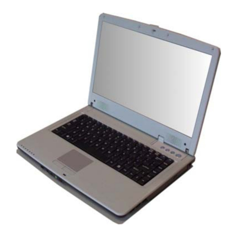
This document provides the hardware specification of 8317, 8317 is a high performance notebook based on AMD
platform with 17” LCD display. The main system base architecture contains two PCBs, the system Mother Board and
the Modem Board.

5
8317
8317 N/B Maintenance
N/B Maintenance
1.2 System Hardware Part(1)
Item Description
CPU - Mobile AMD Athlon 64 62W, “Odessa”, “Newark”
- Mobile AMD Sempron 62W, “Dublin”, “Georgetown”
- CPU Thermal ceiling: 62W
Core logic - ATI RS480M + ULi M1573,
L2 Cache - 256K/512K/1M
System BIOS - Inside 512KB Flash EPROM
- Include System BIOS, VGA BIOS
- ACPI2.0; 2.31 compliant
- Boot from USB mass storage device
Memory - 200-pin SO-DIMM DDR Memory Slot x2
- Support DDR333/400
- 0MB Memory onboard;
- Expandable to 2.0GB
Video Controller - Integrate ATI M10c (RS480M) in north bridge
- Co-layout local frame buffer 4 chips (64M)
ROM Drive 12.7mm Height
- Combo Drive
- DVD Dual
- DVD Super Multi drive
HDD One 2.5"9.5 mm height HDD;
- 5400/7200 RPM Serial ATA HDD
- 40/60/80 GB Capacity
- Support Parallel PATA HDD by option module
- Share 8050QD HDD Daughter card without bridge chip
- ODD, PATA HDD go individual PATA channel. SATA HDD for SATA channel
Display 17.0”W TFT display;
- Resolution WXGA 1440x900
- Resolution WSXGA+ 1680x1050
- Reserve dual channel LVDS display
Keyboard - Key pitch: 19mm, Key travel: 3.0mm
- Windows Logo Key x 2
- W/z Hot Key Functions
- Number pad
Touch Pad - Intelligence Glide pad without scroll button
- 2 touch pad buttons
PCMCIA - Type II x 1
- CardBus Support

6
8317
8317 N/B Maintenance
N/B Maintenance
1.2 System Hardware Part(2)
Audio System - High definition audio spec (Azalia), support S/P DIF output
- 7.1 channel analog output
- 4.1 channel system speaker. Two tweeter speakers (1W Panel), two full range speakers (2W), one
subwoofer (3W)
- Build in microphone
I/O Port I/O:
USB (support USB 1.1 and USB 2.0) port x 6
RJ-11 port x 1 (4Pin)
RJ-45 port x 1
DC input (2.5*5.5*11mm) x 1
IEEE1394 x 1(4 pin)
FIR x 1
Type III B MiniPCI x 1 (For wireless LAN)
Audio (Normal /7.1Analog output):
Audio-out (SPDIF) x 1 (Front) (Locate at machine front side)
Mic-in x 1 (Center, LFB) (Locate at machine front side)
Line-in x 1 (Rear) (Locate at machine rear side)
Line-out x 1 (Locate at machine rear side)
Video
DVI-Digital x 1
TV-Out x 1 (7 Pin S-Video connector NTSC/PAL)
VGA monitor port x 1
Communication - PCI Giga LAN solution
- MDC 56K, V.90 Modem
- Blue tooth 1.2 module (MDC Combo solution)
- 802.11g wireless LAN (MiniPCI optional) with built-in 2 Antenna
- Consumer IR for remote controller
AC adapter - Universal AC adapter 3 Pin 2.5*5.5*11 90W 19V DC output, Input: 100-240V, 50/60Hz AC
Dimensions - 393mm x 275mm x 38mm(Max)
Power Supply - 6/9-cell Li-ion (2200mAH/3.7V) Battery pack
Accessories - AC Adapter,
- Power Cord
- RJ-11 cable, (Option)
Architecture - Support PC2001 specifications;
- WHQL-certified for Windows XP Professional/Home edition SP2
Weight - 3.5KG(TBD)
Options - 128MB/256MB/512MB DDR SDRAM, 6-cell Li-ION Battery Pack, AC Adapter w/o Power Cord,
Certification EMI: FCC, CE, CB
Safety: TUV, UL

7
8317
8317 N/B Maintenance
N/B Maintenance
1.2.1 CPU AMD Athlon 64 Processor
AMD64 instructions
MMX™ and 3DNow!™ technology instructions
SSE, SSE2 and SSE3 instructions
L1 data cache (L1 D-Cache) contains 64 Kbytes of storage organized as two-way set associative
L2 cache contains both instruction and data stream information
The machine check architecture is defined with ECC single-bit detection/correction and double-bit detection
The processor includes a 16-bit Hyper Transport™ technology interface designed to be capable of operating
up to 1600 mega-transfers per second (MT/s) with a resulting bandwidth of up to 6.4 Gbytes/s (3.2 Gbytes/s
in each direction)
The processor’s memory controller provides a programmable interface to a variety of standard DDR SDRAM
DIMM configurations
Both lidded and lidless processors provide the following power management features designed to be
compliant with the Advanced Configuration and Power Interface (ACPI) Specification and Hyper
Transport™ technology
When the HLT instruction is executed, the processor stops program execution and issues a Halt special cycle

8
8317
8317 N/B Maintenance
N/B Maintenance
AMD64 instructions
When the processor recognizes the STPCLK assertion message, it will enter the Stop Grant state on the next
instruction boundary and issue a Stop Grant special cycle
After RESET_L is deasserted, BIOS must program the appropriate clock divisor in the memory
controller configuration registers
The processor provides an on-die thermal diode with anode and cathode brought out to processor pins
Both lidded and lidless processors provide a hardware enforced thermal protection mechanism
1.2.2 ATI RS480M
1.2.2.1 CPU Interface
Supports the mobile and desktop AMD Athlon 64 and Athlon 64 FX processors
Supports 200,400,800,and 1000MHZ Hyper Transport (HT) interface speeds
Supports dynamic link width and frequency change
Supports LDTSTP interface, CPU throttling, and stutter mode

9
8317
8317 N/B Maintenance
N/B Maintenance
1.2.2.2 Memory Interface
Optional dedicated frame buffer (side-port) configuration for a 32-bit or 64bit interface and up to 128MB
of memory
Supports for GDDR memories
Supports for 2M*32(with 64-bit interface only), 4M*32,8M*32,and 16M*16 memory devices
Asynchronous Hyper Transport and memory controller interface speeds
Supports GDDR SDRAM self refresh mechanism
Supports dynamic CKE for power conservation (for GDDR SDRAM only)
1.2.2.3 PCI Express Interface
Compliant with the PCI Express 1.0a Specifications
1*16 graphics interface, which can be divided into two smaller links for use by other devices
Up to four *1 PCI Express general-purpose links

10
8317
8317 N/B Maintenance
N/B Maintenance
1.2.2.4 A-Link Express Interface
1*2(expandable to *4) A-link Express interface (PCI Express 1.0a compliant) for connection to the ATI IXP
1.2.2.5 2D Acceleration Features
Highly optimized 128-bit engine, capable of processing multiple pixels per clock
Hardware acceleration of Bitblt, Line Draw, Polygon/Rectangle Fill, Bit Masking, Monochrome
Expansion, Panning/Scolling, Scissoring, and full ROP support(including ROP3)
Optimized handling of fonts and text using ATI proprietary techniques
Game acceleration including support for Microsoft’s DirectDraw: Double Buffering, Virtual Sprites,
Transparent Blit, and Masked Blit
Supports a maximum resolution of 2048*153632bpp
Acceleration in 8/15/16/32bpp modes
Significant increase in the High-End Graphics WinBench score due to capability for C18 color expansion
Setup of 2D polygons and lines

11
8317
8317 N/B Maintenance
N/B Maintenance
Support for new GDI extensions in Windows 2000 and Windows XP: Alpha BLT, Transparent BLT and
Gradient Fill
Hardware cursor (up to 64*64*32bpp), with alpha channel for direct support of Windows 2000 and
Windows XP alpha cursor
1.2.2.6 3D Acceleration Features
Multi-texturing via one texture-blending unit per pixel pipes, allowing up to thirty-two texel reads per pixel
in a single pass
3D Texture support for bump mapping: emboss, dot product and environment bump maps
Improved precision in anisotropic filtering and bilinear filtering
Complete 3D primitive support: points, lines, triangles, lists, strips and quadrilaterals and BLTs with Z
compare
Improve texture composting
Supports 2536*253632bpp
Hidden surface removal using 16,24,or 32-bit Z-buffering (maximum Z-buffer depth is 24 bits when stencil
buffer enabled) and Early Z hardware

12
8317
8317 N/B Maintenance
N/B Maintenance
8-bit stencil buffer
Bilinear and trilinear texture lighting
Dithering support in 16 bpp for near 24-bpp quality in less memory
Extensive 3D mode support
Anti-aliasing using multi-sampling algorithm with support for 2,4,and 6 samples
Optimized for full performance in true color triple buffered 32bpp acceleration modes
New generation rendering engine provides top 3D performance
Support for OpenGL format for Indirect Vertices in Vertex Walker
Full DirectX 9.0 support (Vertex Shader version 2.0 and Pixel shader version 2.0)
Support for Microsoft’s next generation GDI+ user interface
1.2.2.7 Motion Video Acceleration Features
Video scaling and fully programmable YC

13
8317
8317 N/B Maintenance
N/B Maintenance
1.2.3 ULI M1573
1.2.3.1 PCI Bridge
Supports up to 7 external PCI masters
Parity check on PCI bus AD and CBE# signals
Fully supports PCI Configuration Space Enable (CSE) protocol
Fully compliant with PCI Rev. 2.3
Supports delayed transactions
Dynamic memory prefetch algorithm and programmable post write flush algorithm
Supports concurrent PCI bus burst transfers with zero wait-state
PCI Power Management Interface spec. 1.1 Compliant

14
8317
8317 N/B Maintenance
N/B Maintenance
1.2.3.2 USB Controller
Compliant with USB2.0 specification
Compliant with OHCI 1.0a specification
Compliant with EHCI 1.0 specification
1.2.3.3 HD Audio Controller
Azalia spec 0.7 compliant
1 SDO sharing by all CODEC
3 SDI for 3 CODEC
6 output streams
5 input streams
Corb support with sizes of 2, 16 & 256
RIRB support with sizes of 2, 16 & 256

15
8317
8317 N/B Maintenance
N/B Maintenance
Immediate command/response interface
FIFO sharing technology
Max output sample rate: 8 channel, 32-bit, 192kHz
Max input sample rate: 8 channel, 32-bit, 96kHz
1.2.3.4 System Management Bus(SMB)
M1573 internal System Management Bus (SMBus) host controller is designed based on System Management Bus
Specifications Rev 2.0. It can communicate with the system clock generator and DRAM SPD via SMBus
protocol.
1.2.3.5 Serialized IRQ
M1573 supports Serialized IRQ protocol and thus allows a device using the signal SERIRQ to request for
interrupt service. M1573 Serialized IRQ provides 21 frames including IRQ0, IRQ1, SMI#, IRQ3~IRQ15,
IOCHCK#, INTA#, INTB#, INTC# and INTD#. Moreover, its operating mode (quiet or continuous) and Start
Frame Pulse Width (4/6/8 CICLK periods) are also programmable.

16
8317
8317 N/B Maintenance
N/B Maintenance
1.2.3.6 Advanced Power Management Controller(M7101)
The Power Management Unit fully supports ACPI specifications and legacy power management functions
including: SMM, Stop clock control unit, APM, External SMI-switch control and Programmable counters for
time-out event generation.
M1573 can provide G0 (ON, Standby), G1 (S1: Power On Suspend, S3: Suspend To RAM and S4: Suspend To
Disk), G2 (Soft-Off) and G3 (Mechanical-Off) global system states to minimize the overall system power
consumption. M1573 also provides an extra Standby state for monitoring over 16 peripheral devices’ activity.
M1573 supports programmable Stop Clock with Throttle/ Stop Grant/ Stop Clock control for fitting the ACPI C0-
C3 clock states. M1573 provides several hot plugging events detection and multiple external wake-up events for
satisfying the notebook requirements. M1573 supports the battery, thermal detected logic and system/chip/devices
power plane management logic. M1573 provides full support for Advanced Configuration and Power Interface
(ACPI), On Now technology and OS Directed Power management (OSPM). M1573 also supports the legacy
power management control, such as SMM and SMI features.
1.2.3.7 IDE Controller
Both two channel support ATA/ATAPI 7
Both two channel support up to PIO4, MDMA2 and UDMA5/6

17
8317
8317 N/B Maintenance
N/B Maintenance
Both two channel support Native and Compatibility Mode
Can Combine with SATA port0 and port1 in Compatibility Mode
- SATA port0/1 as channel1, PATA channel 2 as channel2
- PATA channel1 as channel 1, SATA port0/1 as channel2
1.2.3.8 SATA Controller
Implement 4 SATA port support SATA Gen 1 1.5G
Both 4 SATA ports support AHCI 0.98a
Master Only Emulation to support legacy driver in Native Mode
Master/Slave Emulation for legacy driver in Combine Mode
Support SATA II features
Support Native Command Queue ( First party DMA)

18
8317
8317 N/B Maintenance
N/B Maintenance
1.2.4 Memory
No onboard memory
Two 200-pin DDR SDRAM Memory Module
Support DDR333/400

19
8317
8317 N/B Maintenance
N/B Maintenance
1.3 ULI M1573 GPIO Pin Re-Define
Pin
Num Name Type Power Plane Current
Define Notice
Y4 RUNGPIO [0] I/O MAIN POWER WELL LCD_ID0
AF2 RUNGPIO [1] I/O MAIN POWER WELL LCD_ID1
AB5 RUNGPIO [2] I/O MAIN POWER WELL LCD_ID2
AB6 RUNGPIO [3] I/O MAIN POWER WELL MUTE#
When MUTE key is
pushed, Southbridge
will pull low this pin.
E28 RSMGPIO [0] I/O MAIN POWER WELL NA
E29
RSMGPIO [1] I/O MAIN POWER WELL SW_2.5V/2.6V
Power system auto
switch DDR work
voltage according to
DDR type
C29 RSMGPIO [2] I/O MAIN POWER WELL EXT_SMI#
D29 RSMGPIO [3] I/O MAIN POWER WELL SCI#
Table of contents

