Sioux Tools 12' Diameter Gazebo User manual

Gazebo (12’, 15’, 18’, 21’ DIA) – Set Up and Installation Manual 2
Limited Rights Data: This publication is developed and required for use during set up and assembly. It is
provided with the intention that it be used only for official company use, for administrative, or for set up,
installation and maintenance purposes only.
This manual is being provided with limited rights and shall not be reproduced, without the prior written
permission of Sioux Steel Company. Additionally, the contents of this manual will not be used outside of Sioux
Steel Company in whole or in part for manufacture or competitive procurement. This legend shall be included on
any reproductions in whole or in part. Limited rights are not subject to an expiration date.
Introduction
•The purpose of this manual is to explain the setup, installation, and maintenance of the Gazebo 12’, 15’,
18’, and 21’ diameters. It also contains parts lists for reference and ordering replacement parts as needed.
•It is recommended that you read this manual in its entirety for the information available to
provide the proper installation, care, and maintenance of the Gazebo 12’, 15,’ 18’, and 21’ diameters.
The equipment is built to provide many years of dependable service when installed and used properly.
•If you have any further questions, comments, improvements, or suggestions regarding the contents of
any of the information provided, please see the contact information below.
•This machine is covered by one or more United States patents. Refer to www.siouxsteel.com for current
patent information. Or scan this QR Code to go directly to the Sioux Steel website.
WARNING! It is recommended that you read this manual in its entirety for the information
available to provide the proper installation, care, and maintenance of the Gazebo 12’, 15,’ 18’,
and 21’ diameters. The equipment is built to provide many years of dependable service when
installed and used properly.
IMPORTANT! Improper Site Preparation, Assembly and Maintenance of the Gazebo may
invalidate the warranty and cause unnecessary and costly mistakes.
Sioux Steel Company
196 ½ East 6th Street
Sioux Falls, SD 57101-1265
Phone: 1-800-557-4689
www.siouxsteel.com

Gazebo (12’, 15’, 18’, 21’ DIA) – Set Up and Installation Manual 3
Table of Contents
Introduction to Manual
Limited Rights Data ……………………….………………………………………………………………………………………
2
Contact Us Information ………………………………………………………………………………………………………….
2
Chapter 1 – Introduction to Using this Manual
What this Manual Contains ………………………………………………………………………………………………………
4
How to Use this Manual ………………………………….…………………………….…………………………………………
4
Chapter 2 – Safety Instructions
Introduction to Safety Section ……………………………….. ..…………………….…………………………………………
5
Safety Definitions ……………………………………………….. …………………….…………………………………………
5
Safety Statements ……………………………………………….…………………….…………………………………………
5
Chapter 3 – Component Descriptions & Specifications
Features ………………………………………………………………………………...………………………………………… 6
Gazebo Sizes
…………………………………………………………………………………………………………………….. 6
Major Components ………………………………………………………………………………………………………………. 7
Chapter 4 – Set Up and Installation Instructions
General Assembly Information ………………………………….……………………………………………………………….
8
Gazebo Foundation ………………..…..……….………………………………..……………………………………………….
9
Foundation and Anchoring Details .…..……….………………………………..……………………………………………….
10
Center Collar Support ....………………………………………………………………………………………………………...
12
Gazebo Assembly Tips ………………………………………….………….…………………………………………………….
13
Assemble Top Tier Side Panels .……………………………………………………………………………………………….. 14
Torque Chart ..……………………………………………………………………………………………………………………. 15
Install Roof Kit ……………...………………………………….………………………………………….………………………. 16
Fill Cap Installation ……...………………………………….………………………………………….……………………...….
18
Raise Up Assembly and Install onto Anchors ….…...…………………………………………………………………………
19
Optional 1
st
Tier Side Wall Sheets …………………………...………………………………………………………………….
20
Chapter 5 – Maintenance Instructions
Instructions ………………………………….….………………………………………………………………………………….
21
Chapter 6 – Lifting Gazebo Instructions
Maintenance
Lifting Instructions ………………………………………………………………………………………………...
22
Chapter 7 – Exploded Views & Parts Lists
Gazebo 12’ Diameter ………………………………….…………………………………………………………………………. 25
Gazebo 15’ Diameter .……………………………………………………………………………………………………………. 26
Gazebo 18’ Diameter ………………………………….………………………………………………………………………….
27
Gazebo 21’ Diameter .…………………………………………………………………………………………………………….
28

Gazebo (12’, 15’, 18’, 21’ DIA) – Set Up and Installation Manual 4
Chapter 1 – Introduction to Using this Manual
General Description
This manual is a reference for the Gazebo 12’, 15’, 18’, 21’ diameters. It is designed to provide clear and simple
explanations of safety, set up and installation procedures.
What this Manual Contains:
Chapter 1 – Introduction to Using this Manual: Provides an overview of this manual.
Chapter 2 – Safety Instructions: Contains safety guidelines for set up and installation of the Gazebo 12’,
15’, 18’, 21’ diameters.
Chapter 3 – Component Description & Specifications: Provides a description of major components and
lists miscellaneous specifications of the Gazebo 12’, 15’, 18’, 21’ diameters.
Chapter 4 – Set Up and Installation: Provides step by step instructions on the set up and installation of the
Gazebo 12’, 15’, 18’, 21’ diameters.
Chapter 5 – Maintenance Instructions: Contains information on maintenance of the Gazebo 12’, 15’, 18’, 21’
diameters.
Chapter 6 – Exploded Views and Parts Lists: Displays exploded views and parts lists on all the
Components of the Gazebo 12’, 15’, 18’, 21’ diameters.
How to Use this Manual
There are three ways to find information in this manual:
•The Header at the top of each page contains the page number.
•The Footer at the bottom of each page contains the chapter name.
•The Table of Contents lists the chapters, sections, and page numbers of the manual.
Chapter 1 – Introduction to Using this Manual

Gazebo (12’, 15’, 18’, 21’ DIA) – Set Up and Installation Manual 5
Chapter 2 – Safety Instructions
This chapter contains safety guidelines for set up, assembly and installation of the Gazebo 12’, 15’, 18’, 21’
diameters. It describes the safety instructions included throughout this manual, lists safe practices to observe
when setting up the Gazebo 12’, 15’, 18’, 21’ diameters.
You must read this chapter before attempting to set up the Gazebo.
INTRODUCTION TO SAFETY SECTION
SAFETY DEFINITIONS:
CAUTION: Indicates a hazardous situation, which, if not avoided, could result in minor or moderate
injury.
WARNING: Indicates a hazardous situation, which, if avoided, could result in death or serious injury.
DANGER: Indicates a hazardous situation, which, if not avoided, will result in death or serious injury.
MORE SAFETY STATEMENTS:
READ AND UNDERSTAND THIS MANUAL COMPLETELY BEFORE ATTEMPTING TO SET UP AND
ASSEMBLE THE GAZEBO. FAILURE TO PROPERLY SET UP AND ASSEMBLE THE GAZEBO COULD
RESULT IN SERIOUS INJURY OR DEATH TO THE INSTALLERS OR BYSTANDERS.
WATCH FOR THIS SYMBOL. IT POINTS OUT IMPORTANT SAFETY PRECAUTIONS. IT MEANS
“ATTENTION – BE ALERT! YOUR SAFETY IS INVOLVED.”
FAILURE TO DO SO MAY RESULT IN SERIOUS PERSONAL INJURY OR DEATH.
IMPORTANT! It is your responsibility as an owner, operator, or supervisor to know what hazards exist
and to make them known to all other personnel working in the area, so that they too may take any
necessary safety precautions that may be required.
CAUTION: Failure to properly torque all fasteners may result in structural damage to this Gazebo.
CAUTION: Under no condition shall any other bolts, screws, fasteners, or anchor bolts be substituted
for those supplied by Sioux Steel.
IMPORTANT! All bolts, furnished with a neoprene backed washer, must not be tightened, or spun by
the bolt head. Always tighten bolts by spinning the nut. Failure to do so will damage the neoprene seal
and render the sealing qualities of the washer useless.
All foundation specifications used in this manual are for estimating purposes only. Because of many
varying conditions in actual installation, Sioux Steel Company assumes no liability for any results
arising from the use of these stated specifications. Consult a professional engineer for a foundation
designed for your conditions.
Chapter 2 – Safety Instructions

Gazebo (12’, 15’, 18’, 21’ DIA) – Set Up and Installation Manual 6
Chapter 3 – Overview, Component Descriptions & Specifications
This chapter contains descriptions and specifications for the major components of the Gazebo 12’, 15’, 18’, 21’
diameters.
INTRODUCTION
Sioux Steel Grain Bin Gazebos are the perfect addition to any backyard!
With multiple sizes to choose from, there is something for every outdoor space. Enjoy entertaining and the
outdoors in your custom gazebo.
FEATURES:
•4” Corrugated galvanized wall steel.
•Wall sheets and stiffeners are manufactured with 70,000 psi tensile strength steel.
•30-Degree Roof Slopes – Sheds moisture fast off roof panels.
•4” Roof Ribs- make the bin roof more resistant to high winds and larger snow loads.
MULTIPLE SIZES TO CHOOSE FROM:
•12’ Diameter Gazebo
•15’ Diameter Gazebo
•18’ Diameter Gazebo
•21’ Diameter Gazebo
Fig. 3-1: 12’ Diameter Gazebo Fig. 3-
2: 15’ Diameter Gazebo
Fig. 3-3: 18’ Diameter Gazebo Fig. 3-4: 21’ Diameter Gazebo
Chapter 3 – Overview, Component Descriptions & Specifications

Gazebo (12’, 15’, 18’, 21’ DIA) – Set Up and Installation Manual 7
Figure 3-5: Major Components of the Gazebo
SPECIFICATIONS
Available diameters
12’, 15’, 18’ 21’
Wall sheet material.………….…
Wall sheet tensile strength.…….
Wall stiffeners.…….…………….
Galvanized corrugated strength steel
70,000 psi tensile strength
4” steel – 70,000 psi tensile strength
Roof slope ….………………….
30°
Roof ribs.………………….…….
4” steel
Foundation Specifications ……...
(Refer to pages 4-9 for
additional foundation
specifications and
recommendations.)
Concrete Slab: Minimum 4” thick
Footings: Minimum 16” W x 16” D
Slab Footings: 4,000 psi compressive footing depth per local strength codes
Slab Rebar: #4 rebar 16” on center each way
Footings Rebar: #4 rebar in bottom of thickened edge. Rebar must be equal
to ASTM AG15 GR 40 psi.
Soil: Undisturbed or well-engineered 2,500 psi minimum soil bearing capacity
Chapter 3 – Overview, Component Descriptions & Specifications
30° Roof slope sheds
moisture quickly.
4” Wall Stiffeners
add to the strength
of the structure.
Countertop adds to
the versatility and
use of the Gazebo.
Anchor Plates bolt to concrete
base, providing added
strength to the structure.
4” Wide Roof Ribs Resists
high winds and gives
greater snow load strength.

Gazebo (12’, 15’, 18’, 21’ DIA) – Set Up and Installation Manual 8
Chapter 4 – Set Up, Assembly & Installation Instructions
This chapter contains set up and installation instructions for the Gazebo 12’, 15’, 18’, 21’ diameters.
IMPORTANT ASSEMBLY INFORMATION
1. CHECK SHIPMENT
At time of delivery, be sure to check all bundles and parts for proper quantity and condition. Instructions at time of
delivery, refer to the exploded views and parts lists located in the back of this manual. If a shortage or damage
has occurred, do not accept delivery without making note on the freight bill or delivery receipt. If shortage or
damage is found, notify your carrier immediately, so they can send an inspector to make a formal report.
Compliance with the carrier’s procedure is essential for settlement of claim as the company’s responsibility ends
when carrier receives shipment.
2. HELPFUL INSTALLATION TIPS
To facilitate assembly, it is advised that you:
A. Retain your loading list, it will assist you in set up and installation of the Gazebo. It will help you
identify parts and tell how many are needed.
B. Save yourself time by reading the instructions. Read all instructions completely.
C. Keep this manual handy during set up and assembly and for future reference or necessary parts
identification.
D. Have the proper tools and equipment available to complete the installation.
E. Arrange parts in sequence.
F. Do not permit moisture to form between sheets stored outside. If moisture is present, dry at once.
G. When choosing a site for the bin, be sure to consider accessibility, relation to other structures, as
well as power requirements for erection.
3. GENERAL STEP BY STEP PROCEDURES
To assist in the planning, assembly and use of your bin, a general procedure is given below. This procedure is a
guide only and may vary according to your specific requirements.
1. Understand and be prepared to follow the limitations for the use of your specific Gazebo.
2. Carefully read and understand this set up and installation manual supplied with your Gazebo.
3. Consider site requirements.
4. Select an adequate foundation design, prepare site, and construct foundation. You must set up and
install your Gazebo on a cement foundation per the instructions in this manual.
5. Obtain the necessary assembly equipment and tools.
6. Assemble the upper tier of side wall sheets.
7. Assemble the roof.
8. Assemble the optional lower tier of side wall sheets.
9. Anchor the Gazebo to the foundation.
Chapter 4 – Set Up, Assembly & Installation Instructions

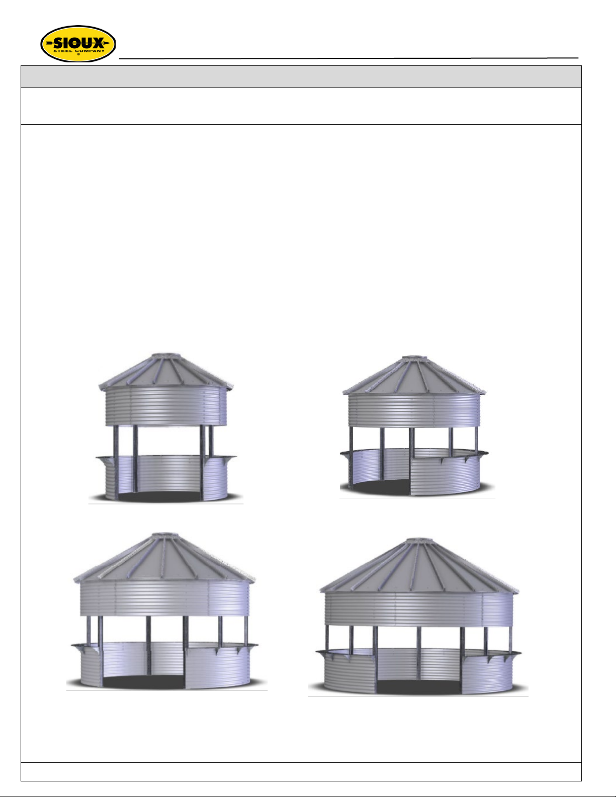
Gazebo (12’, 15’, 18’, 21’ DIA) – Set Up and Installation Manual 9
Foundation for the Gazebo
In all cases, the soil and foundation must be sufficiently
stable and deemed suitable to support the forces
produced by the structure. It is recommended that the
customer consult a qualified engineer to certify the
soil conditions and foundation design for their
location.
Site Selection for the Gazebo
The installation site must be sufficiently level to permit
uniform wall assembly on a support foundation. The site
must be on flat ground and reasonably level to avoid
standing water and erosion problems. In all cases, the
area surrounding the Gazebo must provide sufficient
drainage to prevent soil erosion around the foundation.
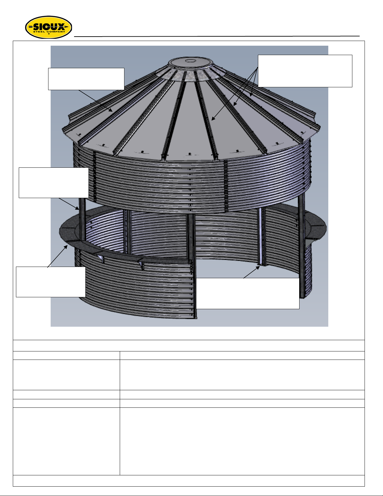
Fig. 4-1: The Gazebo must be build on stable soil
conditions and a concrete foundation.
Soil Analysis and Preparation
Soil under and around the foundation footings and
slab must be undisturbed or well-engineered
compacted back-fill which will provide a minimum soil
bearing capacity of 2,500 lbs. per square foot. Consult
local engineers regarding permissible soil loading at
the site. In addition, sufficient soil borings should be
taken at the site by qualified persons to ensure
adequate soil bearing capacity.
All foundation specifications used in this
manual are for estimating purposes only.
Because of many varying conditions in
actual installation, Sioux Steel Company
assumes no liability for any results
arising from the use of these stated
specifications. Consult a professional
engineer for a foundation designed for
your conditions.
Concrete Requirements
The concrete used in these designs is to have an ultimate compressive strength at 28 days of 4,000 lbs. per
square inch minimum for the slab, and 4,000 lbs. per square inch minimum for the footings. The concrete slab
must at least be 4” thick. The foundation MUST be poured level where the wall will rest to prevent uneven loads
on the wall sheets. The slab should be slightly crowned for moisture control. Never allow the slab to “slope in”
from the side walls, as moisture collection problems will result. Footing depth should be below the frost line,
and a minimum of 16” W x 16” D. Check the requirements in your locality and if necessary, increase the depth
given in the foundation dimension schedule for your specific model Gazebo. Be certain that all anchors are
accurately and evenly installed to insure wall roundness. All anchors must be concentric with the foundation
footing. Never allow foundation penetrations to pass through or interfere with anchor locations. Do not install
less than the specified number of anchors for your Gazebo. See Fig. 4-4.
Concrete Reinforcing Requirements
Rebar splice length must be 16” minimum. Stagger splices with no more than half the re-bar splice at the same
point. Reinforcing (rebar) steel must be equal to ASTM A615 GR 40 KSI. See Fig. 4-4 for more information.
Contact your insurance agent prior to installation to insure you are covered in case of
inadvertent accidents that may occur during assembly.
NOTE: Sioux Steel Company is not responsible or liable for:
Any damage or failure that may occur due to incorrect assembly of the structure.
Any soil analysis or foundation design.
Substitution of components not specified in this installation manual that led to damage or
failure.
Unstable soil conditions or foundation that led to structure damage or failure.
Damage caused by leaning sidewalls.
Any modification of design or structure.
Any bodily injury that occurs during the assembly of the structure or because of modification
to the design or improper construction.
Caustic or corrosive environments that lead to structure deterioration, damage or failure.
Chapter 4 – Set Up, Assembly & Installation Instructions

Gazebo (12’, 15’, 18’, 21’ DIA) – Set Up and Installation Manual 10
FOUNDATION AND ANCHORING DETAILS
The foundation design is to be completed by a qualified
engineer. The minimum slab thickness should be 4 in.
See Fig. 4-4. The thickened edge should be a minimum
of 16” wide and 16” deep. See Fig. 4-4 and refer to
foundation, soil and concrete requirements on page 9.
Anchor bolts can be embedded in the concrete
foundation at the time the foundation is being poured.
Refer to the anchor bolt locations shown in Figures 4-5
thru 4-8 on page 11.
Most installers wait until after the top tier side walls, roof
and stiffeners have been assembled. Then drill in the
anchor bolts at that time. See Fig. 4-3 A, B, C.
The ¾” diameter anchor bolts can be purchased from
Sioux Steel, part No. S192808 (or Epoxy S178235) or
purchased locally. See Fig. 4-3.
EPOXY ANCHOR BOLT DETAILS
Fig.4-2: Anchor with Stiffener
1. Using a rotary hammer drill and drill anchor holes as specified in drawings. See Fig. 4-3 A, B, C.
2. Using compressed air and a brush, clean holes of all dust, slurry, and all foreign matter.
3. Set steel threaded rod in hole and check to see if the projection above surface is 2 ½”. See Fig. 4-3 A, B, C.
4. Inject epoxy starting from the bottom of hole, filling to a minimum of ½ full. See Fig. 4-3 C.
5. Insert threaded rod into hole. See Fig. 4-3 A, B, C.
6. Twist rod in hole to ensure full coverage of epoxy on threads.
See Fig. 4-3 C.
7. Consult directions of epoxy for cure time. Allow to cure.
When considering the drill-in / epoxy anchor details, a good quality
2-part epoxy must be utilized that is made for concrete to steel
adhesion.
Material properties for cured adhesive are as follows:
•Compressive Strength – 10,440 psi
•Tensile Strength – 1,740 psi
Fig. 4-3 A: Anchor Bolt Projections Fig. 4-3 B: Drill Anchor BoltsFig. 4-3 C: Fill Anchor Bolt Holes with
Epoxy and Install All Anchor Bolts
Chapter 4 – Set Up, Assembly & Installation Instructions
NOTE: It is required that all anchor
bolts be installed per
specifications shown on the
following page. Anchor locations
should be marked out prior to
erecting Gazebo to assure
roundness of Gazebo. Anchor
bolts are never to be excluded.

Gazebo (12’, 15’, 18’, 21’ DIA) – Set Up and Installation Manual 11
Fig. 4-4: Slab Foundation
Figure 4-5: 12 FT Anchor Bolt Layout
Figure 4-6: 15 FT Anchor Bolt Layout
Figure 4-7: 18 FT Anchor Bolt Layout
Figure 4-8: 21 FT Anchor Bolt Layout
Chapter 4 – Set Up, Assembly & Installation Instructions
The slab should be a minimum of 4” thick and the thickened
edge should be a minimum of 16” wide and 16” deep
Slope grade line away from
foundation for proper water drainage
#4 rebar at 16” oc each way in slab; centered in slab
#4 transverse rebar at 48” oc
in bottom of thickened edge
(2) #4 rebar continuous

Gazebo (12’, 15’, 18’, 21’ DIA) – Set Up and Installation Manual 12
CENTER COLLAR SUPPORT
A center support collar (See Fig. 4-9) is required to lift
the assembled roof kit and upper tier side walls into
position. The support shown in Figure 4-9 is only a
representation.
Center Collar Supports are available for sale or rental
through other sources.
IMPORTANT! The center support collar represented in
Fig. 4-9 is common for 12’ through 21’ diameter roofs.
The support must be designed to carry the dead and
live loads of the structure during construction.
Figure 4-9: Center Collar Support
CAUTION: Improper design and use of collar support may result in damage to the roof and
personal injury.
Chapter 4 – Set Up, Assembly & Installation Instructions

Gazebo (12’, 15’, 18’, 21’ DIA) – Set Up and Installation Manual 13
Figure 4-12: 15’ Gazebo - Part No. 226004
GAZEBO ASSEMBLY TIPS
It is recommended to review the above drawing and the assembly tips below and learn part names before
beginning the installation. This will speed installation and prevent assembly errors.
1. Note how the upper tier side panels are overlapped on the ends when assembled.
See Fig. 4-12.
2. Note how the wall stiffeners are assembled to the single row of bolt holes in each side panel.
See Fig. 4-12.
3. Locate the label on each side panel. The label has the part number and “This Side Up” arrow. The part
number and “This Side Up” arrow will come into play later in the instructions.
4. During assembly refer to the exploded views and parts lists in the back of this manual to help you to
correctly assemble the Gazebo. See pages 24-28.
5. The Sioux Steel Gazebo is sold in 4 sizes (12’, 15’, 18’, 21’ diameters). The installation steps in this
manual will show only the 15’ diameter option. All diameters are assembled the same.
Chapter 4 – Set Up, Assembly & Installation Instructions
Sheet Panel Mount Holes
Stiffener Mounting Holes
Stiffener
Upper Tier Side Wall Panels
Lower Tier Side Wall
Sheet Panel Mount
Upper Tier Side
Stiffener Mounting
Stiffeners
Lower Tier Side Wall
Upper Tier Side

Gazebo (12’, 15’, 18’, 21’ DIA) – Set Up and Installation Manual 14
1. ASSEMBLE TOP TIER SIDE PANELS
2. Assemble the top tier side panels as follows:
3. Place the center collar support in the center of the foundation adjust to comply with dimension A & B in
Fig. 4-14. See Fig. 4-14.
4. Lay the top tier panels out on the ground around the foundation. Each panel has a label with its part
number and an arrow. The arrow should be pointing up when the panel is installed. Refer to the sheet
layout drawing in Fig. 4-13.
5. Note the panels have a two-bolt row going up and down each end of the panel. See Fig. 4-15.
6. Overlap the ends of each panel and connect the panels using the .438 – 14 x 1.50 bolts and .438 – 14
hex nuts provided. See Fig. 4-15.
7. Only finger tighten bolts. Do not over tighten at this time.
* Optional sheets Figure 4-13: Sheet Layout
Figure 4-14: Center Support and Top Tier of Side Panels

Gazebo (12’, 15’, 18’, 21’ DIA) – Set Up and Installation Manual 15
Chapter 4 – Set Up, Assembly & Installation Instructions
ASSEMBLE TOP TIER SIDE PANELS (continued)
Figure 4-15: Assemble Top Tier Side Panels
CAUTION: Failure to properly torque all fasteners may result in structural damage to this Gazebo.
Torque Requirements
At first, hardware will only be finger tightened. Later in the installation, you will be instructed to torque all
hardware to certain torque values. See chart below.
CAUTION: Under no condition shall any other bolts, screws, fasteners, or anchor bolts be
substituted for those supplied by Sioux Steel.
BOLT TORQUE VALUES / SPECIFICATIONS
NOTE: ALL VALUES ARE IN FT-LBS TORQUE
Bin Bolt
Size Grade Use
Pre-set
Wrench
Torque for
(FT-LBS)
Tolerance
Min Max
.375 Bin
16 x 1.00 GR8.2
Structural fastening, (sidewall) 37 35 40
.438 HH
Bin 14 x
1.50
GR8.2
Structural fastening (sidewall) 47 45 50
.438
CARR -14
x 1.00
GR 5BZ
Structural fastening (stiffener) 33 30 35
5/16 - 18 GD5
Structural fastening (roof and side wall) 22 20 25
Overlap and Assemble Side Panels

Gazebo (12’, 15’, 18’, 21’ DIA) – Set Up and Installation Manual 16
Chapter 4 – Set Up, Assembly & Installation Instructions
INSTALL ROOF KIT
1. Install roof kit hardware to the top edge of the
top tier side panels as shown in Fig. 4-16,
4-17 and 4-18.
2. Install roof clips (#12398) at every 8th hole in
top ring. Install three #12328 intermediate
roof clips in every other hole between all
regular roof clips. Plug all remaining holes
with 3/8” x 1” hex bolts w/neoprene washers.
See Fig. 4-17.
3. To aid installation, it is suggested that a roof
prop be built to hold panels in place on the
center support collar.
4. Only finger tighten all bolts until all panels
have been installed. Do not over tighten at
this time.
Figure 4-16: Roof Hardware Installed Around Top
Edge of Upper Side Wall
Figure 4-17: Roof Hardware
Figure 4-18: Roof Panel Clips
IMPORTANT! All bolts, furnished with a neoprene backed washer, must not be tightened, or spun
by the bolt head. Always tighten bolts by spinning the nut. Failure to do so will damage the
neoprene seal and render the sealing qualities of the washer useless.
Roof Clip
Roof Clip
Intermediate Roof Clip

Gazebo (12’, 15’, 18’, 21’ DIA) – Set Up and Installation Manual 17
Chapter 4 – Set Up, Assembly & Installation Instructions
INSTALL ROOF KIT (continued)
Figure 4-19: Roof Panel Order
ROOF SHEET ASSEMBLY PROCESS:
1. Panel “A” roof sheets should be started at 3 equal
locations around collar. See Fig. 4-19.
2. Attach each roof panel to the roof clips as show
in Fig. 4-18.
3. Holes will have to be counted to assure equal
position of sheets.
4. Panel “B” roof sheets should be installed next.
5. Continue assembling wall sheets in a counter
clockwise direction for the rest of the panels.
6. Finger tighten all bolts. Do not over tighten Figure 4-20: Roof Sheets
at this time.
7. Install the flashing ring. See Fig. 4-21 and 4-22.
Figure 4-21: Roof Flashing Ring
Flashing Ring

Gazebo (12’, 15’, 18’, 21’ DIA) – Set Up and Installation Manual 18
Chapter 4 – Set Up, Assembly & Installation Instructions
FILL CAP INSTALLATION
Install the fill cap as follows:
1. Install fill cap brackets. See Detail A in Fig. 4-22.
2. Install the fill cap to the flashing ring using the
hardware shown in Fig. 4-22.
Figure 4-22: Fill Cap Installation
Figure 4-23: Install Roof Cover and Ring
Fill Cap
Flashing Ring

Gazebo (12’, 15’, 18’, 21’ DIA) – Set Up and Installation Manual 19
Chapter 4 – Set Up, Assembly & Installation Instructions
RAISE UP ASSEMBLY AND INSTALL ONTO
ANCHOR BOLTS
1. Raise up the roof and side panel assembly
using the center support assembly.
2. Install the wall stiffeners. See Fig. 4-25.
3. Lower the roof side panel stiffener assembly
down over the anchor bolts if installed in
foundation earlier in the installation.
See Fig. 4-25.
4. If installing anchor bolts now, drill into
concrete at each wall stiffener and bolt the
stiffeners in place.
5. Finger tighten all hardware. Do not over
tighten at this time.
Figure 4-24: Anchor Bolts
Figure 4-25: Stiffeners Installed on Top Tier Side Walls
Roof Kit
Top Tier
Side Walls
Roof Kit
Stiffener
Stiffeners

Gazebo (12’, 15’, 18’, 21’ DIA) – Set Up and Installation Manual 20
Chapter 4 – Set Up, Assembly & Installation Instructions
Figure 4-26: Install Optional 1st Tier Side Wall Sheets
INSTALL OPTIONAL 1ST TIER SIDE WALL
SHEETS
1. If ordered, install the optional 1st Tier Side
Wall Sheets with hardware provided.
See Fig. 4-26.
2. Install optional countertop brackets and
countertop to 1st tier side wall sheets.
See Fig. 4-26.
Firmly tighten all hardware through out the
installation, the instructions stated to finger tighten all
hardware. Now that the assembly/installation is
complete; firmly tighten all hardware per the Torque
Chart on page 21.
Figure 4-27: Optional Countertop and Brackets
Optional 1st Tier
Side Wall Sheets
Countertop
Countertop
Bracket
Optional Countertop
Optional Countertop
Optional 1st Tier
Side Wall Sheets
This manual suits for next models
3
Table of contents
Popular Outdoor Furnishing manuals by other brands

Forest garden
Forest garden VENPAVNB Assembly instructions

PHI VILLA
PHI VILLA THD7-326-118 Use and care guide

Mimosa
Mimosa 3192508 Assembly instructions

Palram
Palram CANOPIA MARTINIQUE 10x14/3x4.3 How to assemble

NewAge Products
NewAge Products Rhodes 91114 installation guide

Kettler
Kettler TIFFANY 01072-000 Assembly & operating instructions