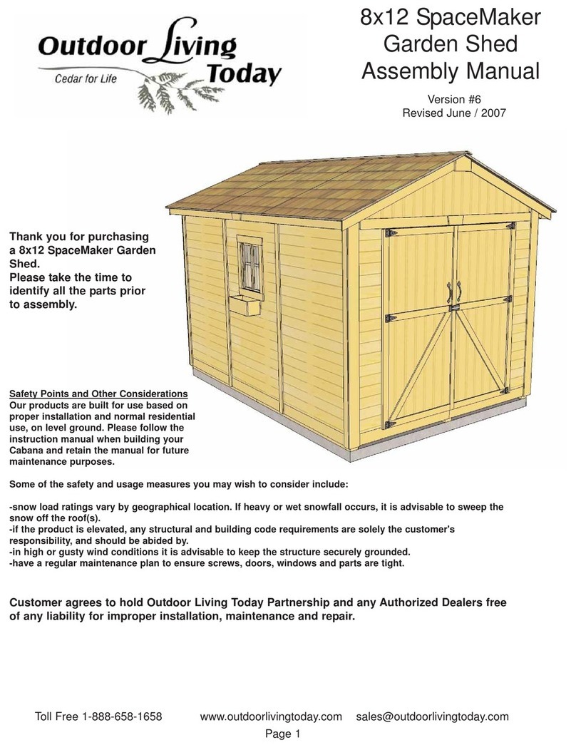
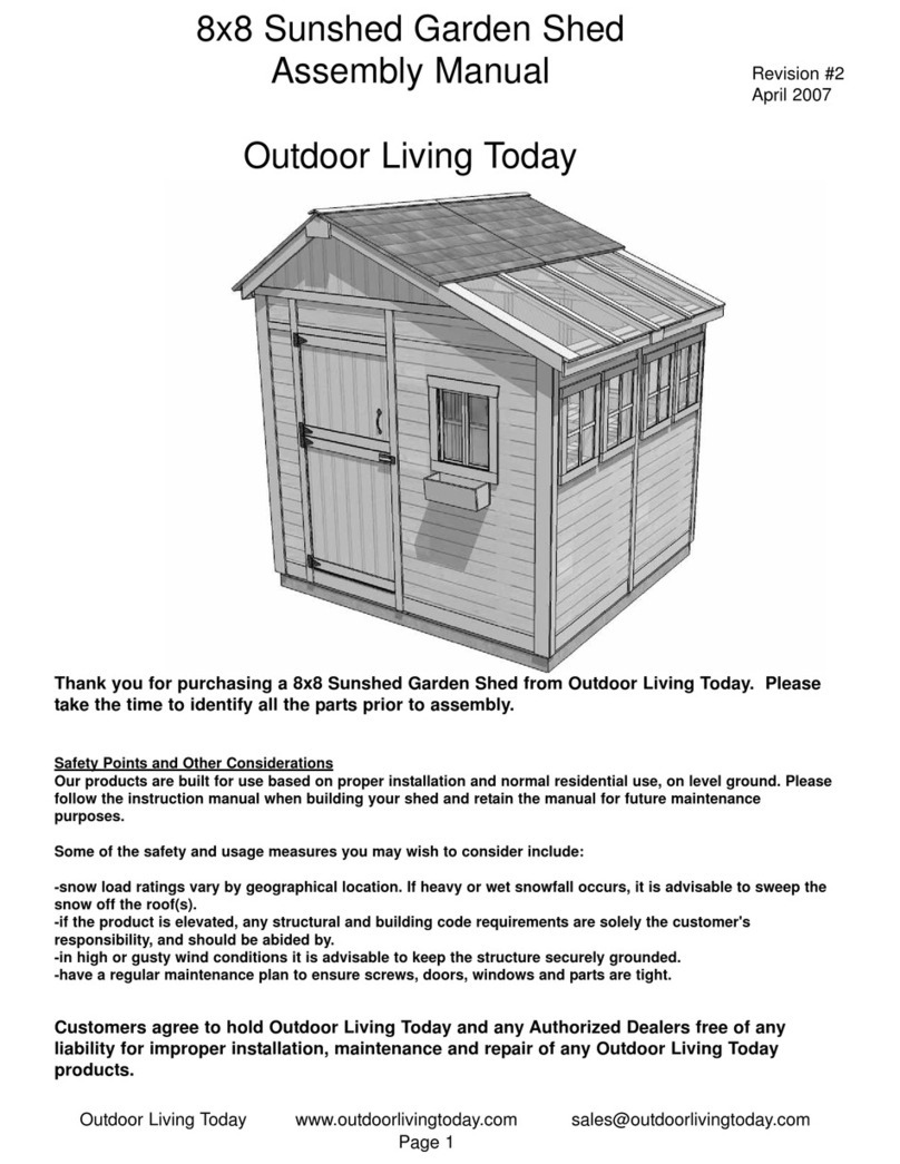
Outdoor living today 5' X 11' Breeze Walkway User manual

Customers agree to hold Outdoor Living Today and any Authorized Dealers free of any
liability for improper installation, maintenance and repair of any Outdoor Living Today
products.
Outdoor Living Today www.outdoorlivingtoday.com sales@outdoorlivingtoday.com
Page 1
5’ X 11’ Breeze Walkway
Assembly Manual
Outdoor Living Today
In the event of a missing or broken piece, simply
call the Outdoor Living Today Customer Support
Line @ 1-888-658-1658 within 30 days of the
delivery of your purchase. It is our commitment
to you to courier replacement parts, free of
charge, within 10 business days of this
notification. Replacement parts will not be
provided free of charge after the 30 day grace
period.
Important - Western Red Cedar Lumber and
Timbers will have surface splitting that occurs
as lumber seasons and drys to the moisture
content in your area. Splitting or “checking”, as
it is referred to, can be 1/8” to 1/4” wide and can
run several feet. This does not diminish the
structural integrity of the material in any way.
Version #2
July 17/2009

Parts Lists: Finished Size
T W L Qty.
A - Posts 5 1/2” 5 1/2” 108” 4
D - Main Joist (2” Notch Down) 1 1/2” 5 1/2” 138” 4
E - Girders (Deep Notch Down /Drilled) 1 1/2” 5 1/2” 138” 2
F - Blocking 1 1/2” 5 1/2” 18 5/8 6
B - Side Girders (Deep Notch Top) 1 1/2” 5 1/2” 59 1/2” 2
I - Stub Joists 1 1/2” 5 1/2” 14 1/2” 12
G & H- Corner Brackets 1 1/2” 5 1/2” 36” 4
K - Corner Bracket Post Mount 3/4” 4 1/2” 10 1/2” 4
L - Post Skirting Caps 3/4” 8 3/8” 1 1/2” 16
M - Post Skirting - Slotted 1 1/2” 8 3/8” 7” 8
N - Post Skirting 3/4” 5 7/8” 7” 8
P - 2x2 Cross Members 1 1/2” 1 1/2” 59 1/2” 14
Q -2x2 Cross Member Template (not Shown)1 1/2” 1 1/2” 5 1/4” 2
Thank you for purchasing one of our Breeze Walkway. Please
take the time to identify all the parts prior to assembly.
B
A
A
F
P
I
E
K
Plus Hardware Kit that includes;
( 2” , 3”, 4” Deck Screws)
2” Stainless Steel Screws
Handful of Finishing Nails
3/8” Lag Bolts with Washers
Tools Required:
Work Gloves,
Screw Gun (square drive bit included in kit)
1/8” & 1/4” Drill Bit for pilot holes
9/16” Wrench
Level
2 Tall Step Ladders
9ft string line
Assembly Time:
1 Day (does not include site preparation)
Specifications:
Outside Width Post to Post: 101”
Inside Width Post to Post: 90”
Outside Depth Post to Post: 41 1/2”
Outside Depth Post to Post: 30 1/2”
5X11 Breeze Walkway
101” OUTSIDE
POST TO POST
D
Outdoor Living Today www.outdoorlivingtoday.com sales@outdoorlivingtoday.com
Page 2
Outside Girders
have deeper
Notches and are
Pre-drilled.
G &H
41 1/2” OUTSIDE
POST TO POST
Post Mounts Not
Included in Kit
Front
Side
L
M
N

Laying out your Footprint
To determine the proper placement of your
5.5” x 5.5” Posts, see the exploded view on
Page 2 and the Illustration to the left to find
the measurements and to determine their
correct positions. Outside Post to Post
measurements are: 101”. Inside Post to Post
measurements are 90”.
Take diagonal measurements to check your
layout for square. We recommend that you fix
Posts to ground using Steel Post Bases or
Saddle Brackets fixed on cement footing. If
attaching Posts to pre-existing deck, we
recommend that you purchase Post / Deck
Mounting Brackets. In both cases, Post
Mounting hardware can be found at most
Hardware Stores.
90”
B
Lag Screws
/ Washers
13.5”
8”
A
Deep Notch
facing up
and inside
flush with
post.
Outdoor Living Today www.outdoorlivingtoday.com sales@outdoorlivingtoday.com
Page 3
Important - Western Red Cedar Lumber
and Timbers will have surface splitting
that occurs as lumber seasons and drys
to the moisture content in your area.
Splitting or “checking”, as it is referred
to, can be 1/8” to 1/4” wide and can run
several feet. This does not diminish the
structural integrity of the material in any
way.
1. On flat level ground, lag-screw Side
Girder (B) to two Posts (A) approximately 8”
from top of Post. B- Girders are 59 1/2” long
and have top deep notches (2 3/4”).
Complete 2 sets of Girder /Post Sections.
Front
Side
May want to consider
drilling 1/4” pilot
holes to assist in
inserting lag bolts.
30 1/2”
95”

2. Lift up a completed
Post/Girder section slowly
and carefully. Make sure Side
Girder is facing outward.
3. Position bottom of Post in existing
Post Mounts.
4. Secure Post to Post Hardware.
Post
Mounts
Lag Screws
5. Locate Girder (E) and lift into
position between both
B-Girder / Post Assemblies. The
E-Girder has a deep notch facing
down on each end and is 138” long.
Lift, position and attach the
second Post / Girder section to
Post Hardware.
B-Girder
facing out.
Deep Notch facing down.
Outdoor Living Today www.outdoorlivingtoday.com sales@outdoorlivingtoday.com
Page 4
E
Front

6. Carefully lower E- Girder down into
notch of H-Side Girders. Be careful not to
twist the Girder when dropping down into
place. Lag screw(2) Girder to Post.
Lag screw
to Post
7. Lift, position and Lag screw the
second E-Girder to Posts.
8. On level ground, position 1 Main
Joist (D) and 6 Stub Joists (I).Main
Joists are pre-marked for Stub Joist
and Blocking position.
E-Girder
E-Girder
Pre-marked for Stub
Joist placement
D
I
Notches facing down
Outdoor Living Today www.outdoorlivingtoday.com sales@outdoorlivingtoday.com
Page 5
E

9. With Stub Joists positioned correctly
on Joist, attach each Stub Joist with 2 - 3”
screws. Stub Joists should be flush with
top and bottom of Main Joist with all
notches facing down. There are two Main
Joist / Stub Joist assemblies, complete
both now. 2 - 3”
screws
10. Carefully lift up completed Stub Joist /
Main Joist assembly and place between
H-Side Girders flush against posts and notch
sitting down into girders.
4” long
screws
11. Attach all Stub
Joists and Main Joist
to girders with
1 - 4” screw per
piece. Complete
both assemblies.
Consider drilling
1/8” pilot holes to
assist in screw
insertion.
Outdoor Living Today www.outdoorlivingtoday.com sales@outdoorlivingtoday.com
Page 6

12. On a flat surface, position Blocking (F)
where marked on Main Joist (D) and screw with
2 - 3” screws per piece. Blocking should be
flush with top and bottom of Main Joist with all
notches facing down.
F
D
D
Main Joist is pre-marked
for blocking placement.
2 - 3”
screws
per piece.
Completed Ladder Section
13. Carefully lift up completed
Ladder Sections and place between
H-Side Girders. You will require a
helper to assist in lifting up the
ladder section.
Outdoor Living Today www.outdoorlivingtoday.com sales@outdoorlivingtoday.com
Page 7
14. Lower and position Ladder on
H-Side Girders evenly between Posts
so notch of joist sits on H - Girder.
15. Attach Ladder to H-Side Girders with
4 - 4” screws per Ladder. Screw from top
down into girder.

Outdoor Living Today www.outdoorlivingtoday.com sales@outdoorlivingtoday.com
Page 8
(H) Right Side
Corner Bracket
(K) Corner
Bracket
Post
Mounts
Wooden
Dowel
17. To assist you with Bracket and Post Mount alignment, both the
end of the Bracket and Post Mount have been drilled for a Wooden
Dowel. Wooden Dowels are found in the Hardware Kit Bag. Insert
a Wooden Dowel in end of Corner Bracket first and then push Post
Mount onto Dowel until Bracket and Post Mount are flush together.
Align Post Mount parallel with Bracket.
16. There are 2 Left (G) and 2 Right Sided
Corner Brackets (H). Corner Bracket Post
Mounts (K) must be attached to the
bottom end of each Corner Bracket before
attaching to Posts.
Hole
Bracket
and Post
Mount
aligned
parallel
with each
other.
18. With Bracket and Post Mount correctly aligned, screw Post Mount to Bracket with 2 - 2 1/2”
screws. Important- Drill pilot holes in Post Mounts and Bracket to prevent wood from splitting!
Complete all remaining Brackets/Post Mount connections.
2 - 2 1/2” screws
Important:- Drill pilot
holes to prevent
wood from splitting.

20. Position Corner Bracket so
Joist Mount is flush with bottom of
Blocking or Main Joist and Post
Mount is flush against Post. When
in correct position, attach joist
mount to girder and joist/blocking
with 2 - 3” screws per side.
Outdoor Living Today www.outdoorlivingtoday.com sales@outdoorlivingtoday.com
Page 9
21. With Bracket
centered on Post, attach
Bracket Post Mount to
Post with 6 - 2” Stainless
Steel Screws. Attach
remaining Corner
Brackets to Posts. There
will be two brackets per
post.
19. Lift completed Left Sided Corner Bracket up and align bottom
of Bracket Spacer flush with bottom of Girder. At bottom of Corner
Bracket, align Post Mount evenly and tight against Post. When
correctly aligned, secure at top with 2 - 4” Screws. To secure Post
Mount, use 6 - 2” Stainless Steel Screws. Note, Post Mount and
Top of Bracket are pre-drilled.
Bracket
Spacer flush
with bottom
of Girder.
Important- Posts may need to be aligned so they are
true and square to mount Corner Brackets correctly.
Use a Level to determine correct Post position.
Left Sided
Corner Bracket
4” screws countersunk
1/2” below surface.

Outdoor Living Today www.outdoorlivingtoday.com sales@outdoorlivingtoday.com
Page 10
Skirting
Post
Skirting
Cap
22.To complete your Breeze, attach Post Skirting around each post. Position 2 Slotted Post Skirting
Pieces on opposite sides of Post. Slide a Post Skirting between grooved slots until flush at top.
23. Align Post Skirting Cap tight
against Post and equally from side to
side of skirting framing. Nail Cap down
into Skirting with 4 - 1 1/4” finishing
nails.
24. Slide in 2nd Post Skirting piece and position and nail Post Skirting Cap as per Step 28. Place
remaining Post Skirting Caps on Skirting and nail as per Step 28. Complete remaining Post Skirtings.
Post Skirting - Slotted

25. Lift and position 1 - 2x2 Cross Members (P) up against outside Posts on both sides. Align with
outside of H-Side Girders. Pre-drill Members first and attach with 4 - 2” screws per piece. At each end,
attach a String (approx. 9’ long) using nails to help align interior Members in Steps 26-28.
26. Using 2x2 Cross Member Templates (Q), align and attach both outside 2x2’s as per Step 25.
27. Using the 2x2 Cross Member Templates, align and attach interior 2x2’s starting at the 2nd
interior Stub Joist. Use 4 Members spaced 5 1/4” apart. Attach as per Step 25.
Outdoor Living Today www.outdoorlivingtoday.com sales@outdoorlivingtoday.com
Page 11
Alignment
String
2x2 Cross
Member
Template
2nd Interior
Stub Joist

28. Continue attaching 2x2’s using Template for spacing and positioning ends with alignment strings.
Attach as per Step 26.
We hope your experience constructing
our Breeze Walkway has been both positive and
rewarding.
We value your feedback and would like to hear
back from you on how well we are doing in the
following areas:
1. Customer Service
2. On Time Shipping
3. Motor Freight Delivery
4. Quality of Materials
5. Assembly Manual
6. Overall Satisfaction.
Please call, write or email us at:
Outdoor Living Today Partnership
P.O. Box 96
Sumas, Washington
98295
Toll Line: 1.888.658.1658 | Fax: 1.604.462.5333 | sales@outdoorlivingtoday.com
The materials contained in this Assembly Manual may
be downloaded or copied provided that ALL copies
retain the copyright and any other proprietary notices
contained on the materials. No material may be
modified, edited or taken out of context such that its
use creates a false or misleading statement or
impression as to the positions, statements or actions.
Page 12
Completed 5x11
Breeze Walkway!
Other Outdoor living today Outdoor Furnishing manuals
Popular Outdoor Furnishing manuals by other brands
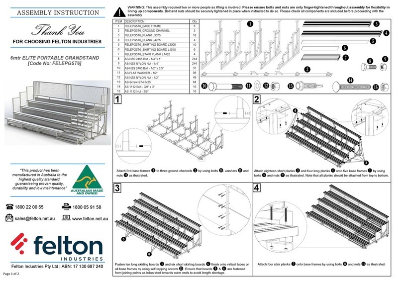
Broyhill
Broyhill SANDPOINTE Assembly instructions

PatioTree
PatioTree 10'x10' Calais hardtop gazebo Assembly manual

Safavieh Outdoor
Safavieh Outdoor PAT6729 quick guide

CAZEBOO
CAZEBOO SANTA 400S300 manual

VEVOR
VEVOR AP-SS-001 user manual

Fortress Building Products
Fortress Building Products H Series installation instructions

SHANGRI-LA
SHANGRI-LA SLSAD4PCLGB user guide

Hanover
Hanover LAVALLETTE7PC owner's manual

Kettler
Kettler GRANADA 0301601 Assembly & operating instructions

Bilt
Bilt HOME ACCENTS Holiday 22SV23269 Easy Assembly and operation instructions

Rutland County Garden Furniture
Rutland County Garden Furniture Polycarbonate Car Port 2 Post Assembly instructions

Palram
Palram Palermo 3000 manual