Siqura SA PTZ Series User manual
Document name: saptzseries_v4-IM-EN.docx
Installation manual
SA PTZ Series
316L Fixed camera station

2 of 7 | P a g e
Copyright © 2019 Siqura B.V.
All rights reserved.
SA PTZ Series
Installation Manual v4 AIT55
Nothing from this publication may be copied, translated, reproduced, and/or published by means of
printing, photocopying, or by any other means without the prior written permission of Siqura.
Siqura reserves the right to modify specifications stated in this manual.
Brand names
Any brand names mentioned in this manual are registered trademarks of their respective owners.
Liability
Siqura accepts no liability for claims from third parties arising from improper use other than that
stated in this manual.
Although considerable care has been taken to ensure a correct and suitably comprehensive description
of all relevant product components, this manual may nonetheless contain errors and inaccuracies. We
will help us to further improve our documentation.
How to contact us
If you have any comments or queries concerning any aspect related to the product, do not hesitate
to contact:
Siqura B.V.
Meridiaan 32
2801 DA Gouda
The Netherlands
General : +31 182 592 333
Fax : +31 182 592 123
E-mail : siqura@siqura.com
WWW : siqura.com
Note: To ensure proper operation, please read this manual thoroughly before using the
product and retain the information for future reference.
3 of 7 | P a g e
DESCRIPTION
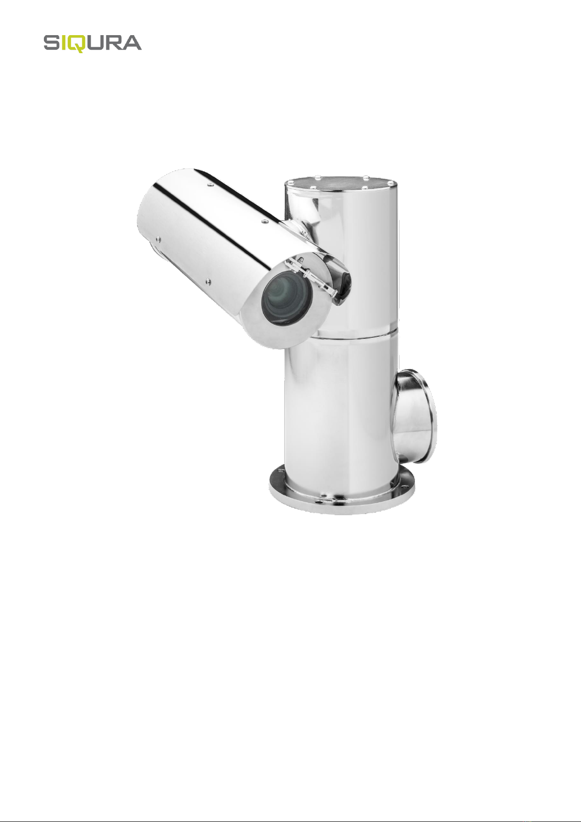
The SA-PTZ (T) camera housing is a rugged corrosion proof PTZ camera station designed for use in onshore, offshore, marine
and heavy industrial environments. The camera housing is constructed from electro-polished 316L stainless steel for maximum
corrosion protection and is fitted with an 316L sun-shield, a thermostatically controlled heater, and integrated wiper. Combined
with a IP zoom camera or thermal module the SA-PTZ(T) transforms in a full featured PTZ camera station. The PTZ T is fitted
with a ∅70 mm germanium window for thermal TC36 or TC640 modules. The housing is not sold separately, it is only available
in combination with a Siqura daylight camera module or thermal module and an interface (INT-RJ/SM/MM).
MODELS
SA-PTZ24 Safe Area PTZ Camera 316L 24VAC
SA-PTZ115 Safe Area PTZ Camera 316L 115VAC
SA-PTZ230 Safe Area PTZ Camera 316L 230VAC
SA-PTZ24T Safe Area PTZ Thermal Camera 316L 24VAC
SA-PTZ115T Safe Area PTZ Thermal Camera 316L 115VAC
SA-PTZ230T Safe Area PTZ Thermal Camera 316L 230VAC
INSTALLING THE CAMERA
Prior to installation and operation, carefully read all instructions the in this manual and heed all warnings.
Unpack this equipment and handle it carefully. If the package appears to be damaged, notify the shipper immediately.
Use the original packaging to transport the unit. Disconnect power supply before moving it. In case of returning the equipment, the original
packaging must be used.
Make sure that the installation surface can support at least four times the weight of the unit in normal operating conditions. In case of
excessive external stress (e.g. vibration, strong winds or impact), the equipment may need additional means of protection.
Proper stainless steel hardware should be carefully chosen to fasten the unit to the surfaces.
Use caution when lifting and assembling the unit. It is recommended that non-slip protective gloves be worn during installation. The unit
could bear sharp edges.
Trying to manually force the wiper will result in damaging the device and will void the warranty.
To maintain the IP rating of the unit, adequate cable glands must be used. The unit must be tightly closed when operating.
For security reasons, do not install the unit in the proximity of water containers and never push objects or pour liquids into the unit. The
unit can be safely used in damp environments or outdoors, as long as the connectors are properly sealed.
Video and data cables should not share the same conduit with supply voltage cables. Whenever EMC is an issue, adequately shielded
cables must be used.
Open only the covers pointed out in this installation manual. Other covers should be open only by the manufacturer.
This equipment has been designed to fit in harsh environments requiring little or no maintenance. Suggested inspection interval is 6
months, but extremely harsh environments may require more frequent inspection and maintenance checks. On each inspection check the
O-ring seals and the eventual window wiper blade integrity. Replace them if necessary.
Check cables, electrical connections and mounting hardware for integrity and tightness. Replace or tighten any damaged/loose part.
Remove PVC protective film from the camera housing sunshield after installation.
Operating temperature: -20° +75° C (-4° +167° F).
Before performing any operation, turn off the power. The installation of the unit can be performed only by qualified personnel in accordance
with the regulations in force. Do not connect the unit to a supply circuit unless the installation is completed.
Check carefully the supply voltage marked on the label. Incorrect Power Supply Voltage may damage the unit. Do not overload the terminal
connection, as it may cause a fire or electrical shock hazard.
An all-pole mains switch with an opening distance between the contacts at least 3 mm in each pole must be incorporated in the electrical
installation. The switch must be equipped with protection against the fault current towards the ground (differential) and the overcurrent
(magnetothermal, maximum 15A). It must be very quickly recognizable and readily accessible. A suitable blow fuse must also be installed
for protection.
For connection to the mains, use a multipolar cable having minimum 3x1,5 mm2 (15 AWG). The main cable must be at least protected by
an ordinary PVC sheath.
Fasten all the cables inside the housing with cables ties or other fixing means to avoid the electrical contact with surrounding parts in case
that terminal blocks screw off.
Electrical connections (such as plugs and cords) must be protected from potential hazardous environmental factors (e.g. foot traffic, hitting
objects).
Ensure that the unit case is properly earthed, connecting all the earth ground studs. Earth cable should be about 10mm longer than the
other cables on the connector, in such way that it won't be accidentally disconnected if the cable is stretched or pulled.
When leaving the unit unused for long periods, disconnect supply cables.

4 of 7 | P a g e
INSTALLING THE NOZZLE BRACKET*
M6 nut
2x M6 washers
bracket
* Not available for the thermal versions SA-PTZ T.
PERFORM ELECTRICAL CONNECTIONS
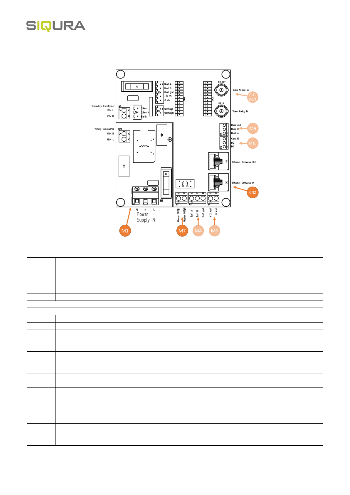
Open the base junction box and perform the connections on the interface board. The screw terminal blocks are used for the field
installation. It must be noted that each plug-in connector is different in shape and/or colour to avoid any wrong connection. The
connections should be performed according to the below:
5 of 7 | P a g e
Connection board
Field installation
ID
Name
Notes
M1
Supply voltage
Depending on model: 24VAC (max current: 6A) or 230VAC 50/60Hz (max current: 0,75A).
PE (Protection Earth) must be connected.
M7
Auxiliary AC output
Designed to activate washer systems. Generally activated via AUX 2 in Pelco D. The
activation lasts 5 seconds.
CN2
Ethernet
100base-TX fast Ethernet connection
Pre- or not connected (Not to be changed)
ID
Name
Notes
M3
Supply voltage
Supply voltage for telemetry receiver and any 24VAC device inside the unit.
M4
Data input (RS485)
Reserved. (Pelco D Protocol to control telemetry receivers: 2400,N,8,1).
M5
RS485 bus
Communication bus (RS485) for telemetry receiver. This provides the auxiliary DC output
(M7).
M6
Auxiliary DC output
Reserved. (12 VDC. Max: 0,4A. Any connection of this Aux must be performed inside the
base junction box.)
M8
Auxiliary AC output
Auxiliary AC output connected to AUX 2 of telemetry receiver.
M9
Auxiliary data
(RS485)
Reserved.
M10
Auxiliary digital
input
Reserved: (Dry contact or open collector auxiliary input. Close IN1 (Collector) to Com IN
(Emitter) to activate AUX1 (wiper). Close IN2 (Collector) to Com IN (Emitter) to activate
AUX2 (washer). Com IN=GND.)
CN1
Ethernet
Fast Ethernet to IP camera
CH1_IN
Analog input
Reserved
CH1_OUT
Analog output
Reserved
CN3
Auxiliary connector
Reserved
CN4
Same as above
Reserved

6 of 7 | P a g e
Fuse values
The following fuse values are used:
Fuse name
Fuse value
F1
8A T 250VAC 5x20
F2
10A T 250VAC 5x20
All the fuse must be T type (time lag).
Different supply voltage can be supplied and may require different fuse values. In such cases, please contact Tecnovideo.
SETTING THE UNIT ADDRESS (Analog version only)
The 8 way dip-switch on the telemetry receiver (DIS1) can be used to set up the unit address
(binary). When a switch is on the ON position, the relative digit has value 1, otherwise the value
is 0. Switch 1 is referred to the least significant digit (20), while switch 8 is referred to the most
significant digit (27).
For example, the address 13 (00001101 in binary) can be set up turning ON the switch 1, 3 and
4 (see figure).
The same address must be set on both telemetry receivers of the PTZ unit.
SETTING THE TELEMETRY RECEIVER
The 2 way dip-switch on the telemetry receiver (DIS2) is used to configure the board to work
for pan or for tilt movements.
When Switch 1 is on OFF (0), the board is configured to work as pan. When Switch 1 is on ON
(1), the board is configured to work as tilt. Switch 2 is reserved and must be kept on OFF (0).
This must be done only in case of board replacement.
Fig.1: Pan setting Fig.2: Tilt setting
Default limits
The unit is set with default values to achieve the following tilt angles: +/- 90° (up/down). Pan limits are not set.
Factory limits are about +/- 100° Tilt (up/down). No factory pan limits (continuous rotation).
Changing the default limits
Left Limit
Right Limit
Up Limit
Down limit
Preset Set 70
Clear limit
Preset Set 71
Clear limit
Preset Set 72
Clear limit
Preset Set 73
Clear limit
Preset Set 80
Set limit
Preset Set 81
Set limit
Preset Set 82
Set limit
Preset Set 83
Set limit
Note: setting the Pan limits (set 80 and 81) will delete all the pan saved presets.
1
2
3
4
5
6
7
8
ON (1)
1
2
ON (1)
1
2
ON (1)

7 of 7 | P a g e
Presets
Preset from 1to 69 and from 100 to 150 can be used to set/call specific positions. The other presets are factory reserved and
cannot be used to set/call specific positions.
On startup, the unit will perform a zero-axis (in which the unit won't accept any further command). Setting preset 74 changes
the behaviour of the unit to perform the zero-axis on the first command received after the startup. Setting preset 84 switches
back this behaviour and make the unit perform the zero-axis on startup. Calling preset 92 performs a pan and tilt zero-axis, while
call 90 performs a pan zero axis and 91 performs a tilt zero axis. Calling preset 93 moves the unit to zero position (0°,0°) both
on pan and tilt axis.
Preset Call 88 activates auxiliary output AUX1 (wiper). Auto off after 10 seconds.
Preset Call 89 activates auxiliary output AUX2 (washer). Auto off after 5 seconds.
Preset Call 99 calibrates the Camera Pots in case of motorized lens (needed the first time the camera is connected).
Preset Call 200 activates the automatic wiper and washer cycle systems.
This manual suits for next models
6
Table of contents
Other Siqura Camera Accessories manuals


