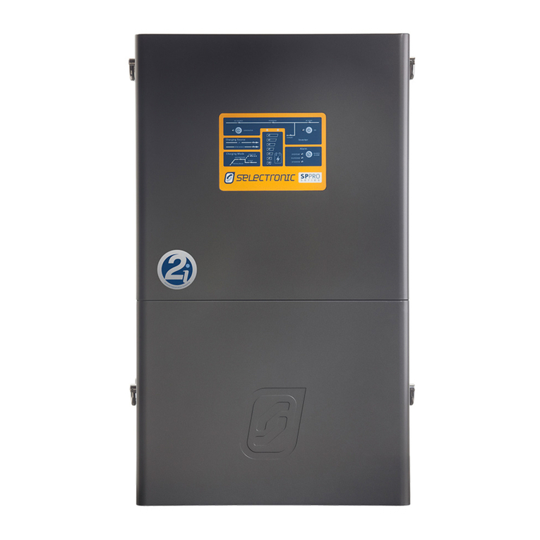
Selectronic myGrid Quick start guide

IN0025 - 004952 Revision 05 –1 of 35
POWER PERFORMANCE PASSION
myGrid
Installation Notes
myGrid Installation Notes
Introduction
myGrid kits provide an easy to install, compliant, Solar Hybrid (On-Grid) or Off-Grid battery
system.
These installation notes outline all the processes required to effectively install each of the
myGrid kit configurations helping the installer to gain the most benefit from using a myGrid kit.
myGrid Installation Overview
There are two major parts to each kit:-
SP PRO or SP PRO GO Interactive Inverter Charger
Battery Enclosure including side mounted DC switchbox
The battery enclosure is designed to sit on the floor and the SP PRO or SP PRO GO is wall
mount. Connection points between these two parts have been designed to allow flexibility in
positioning to suit many varied locations.
The battery enclosures in the myGrid kit are modular and each section is called a frame. Each
frame can hold four myGrid batteries. The picture above is a two frame battery enclosure plus
left hand mounted DC Switchbox. The DC Switchbox contains the main battery circuit breaker
and the precharge/battery sense circuit breaker under a protective cover and can be mounted
on either the left hand side or the right hand side of the battery enclosure.
OR
PLUS

IN0025 - 004952 Revision 05 –2 of 35
myGrid
Installation Notes
INSTALLATION LOCATION
The myGrid kit includes short cabling for minimum losses so the SP PRO or SP PRO GO and
battery enclosure need to be installed within close proximity of each other. The battery
enclosure and the DC switchbox is suitable for installation outside however it is advisable that
the installation is somewhat protected from the elements.
The distance to the main AC Switchboard must also be considered. AC feeds are required to go
into and out of the SP PRO or SP PRO GO.
Battery Enclosure Dimensions
Dual Frame Enclosure shown.
Quad Frame enclosure is twice the width.
Single Frame Enclosure is half the height.
No minimum spacing is required either side of the battery enclosure. All maintenance access is
from the front and top.

IN0025 - 004952 Revision 05 –3 of 35
POWER PERFORMANCE PASSION
myGrid
Installation Notes
CHOOSING MANAGED CIRCUITS
When installing a myGrid kit in a Solar Hybrid system rewiring of the installations AC
switchboard may be required to split out the load circuits that need to be managed.
If all the installation’s load circuits total less than 63 amps (the SP PRO OR SP PRO GO’s feed
through capacity) it may be easiest to make all the load circuits (excluding off peak loads like
hot water) managed. This provides energy management of all the house loads via SP LINK
however the customer may need to manually manage the loads during a grid outage to prevent
a system overload.
PLACEMENT OF SP PRO OR SP PRO GO
The SP PRO or SP PRO GO needs to be mounted with sufficient clearance on all sides with
allowance for air flow and cabling. See SP PRO or SP PRO GO Instruction Manual for full
details.
ADDITIONAL PARTS TO BE SUPPLIED
Some additional parts are required to be supplied by the installer.
AC Cabling –sized to suit maximum AC demand of AC Loads and charging capacity.
25mm Conduit
Mounting hardware
Solar panels, Grid Inverter, cabling and isolators –as required
KIT CONTENTS
Battery enclosure metalwork components
Pre-assembled and wired DC switchbox
Screws for assembly of the battery box
Insulated Ring Spanner to tighten battery clamps
Torx bits to suit screws provided
DC battery cables
DC battery sense cables
Pre-assembled Battery interconnects
Selectronic SP PRO or SP PRO GO interactive inverter
Sonnenschein 330AH 6V Gel batteries

IN0025 - 004952 Revision 05 –4 of 35
myGrid
Installation Notes
Assemble Battery Enclosure –Part A
The kits are shipped ready to be assembled. Each kit comes with the required number of
frames to suit the number of batteries supplied.
The battery enclosure is modular for ease of assembly and versatility. Each frame is individually
assembled before all the assembled frames are bolted together to form the battery enclosure.
ASSEMBLE FRAMES
Each frame supplied must be assembled.
Install Frame Vents
Frame vents are installed into the bottom shelf frame(s) only.
NOTE: Frame vents are packed with the battery enclosure lid(s).
Place the Frame Vent on the shelf support angle and move in the direction shown in
Figure 1 until it contacts the inserts on the front and back faces of the frame.
Rotate the top of the Frame Vent in the direction shown in Figure 2 and push it down
into the gap between the frame bracket verticals and the shelf support.
Secure the Frame Vent to the shelf support using M4 x 12mm long screws (2 off)
supplied as shown in Figure 3.
Figure 1 Figure 2 Figure 3

IN0025 - 004952 Revision 05 –5 of 35
POWER PERFORMANCE PASSION
myGrid
Installation Notes
Install Shelfs into Frames
Place the Shelf on to the frame brackets so that the inner face of the upward fold is flush
with the inner faces of the frame brackets as shown in Figure 4.
NOTE: Both Left and Right frames brackets are identical.
Secure in place using M6 x 16mm screws (4 off) supplied.
Figure 4
Install Rear Cover to Frames
Locate the Rear Cover (with knockouts) onto the Frames as shown in Figure 5
Secure in place using the M6 x 16mm long screws (4 off) supplied.
Figure 5
M6 x 16mm long
(4 off)
Inner face of shelf
and frame brackets
to be flush
Upward fold back
M6 x 16mm long

IN0025 - 004952 Revision 05 –6 of 35
myGrid
Installation Notes
ASSEMBLE FRAMES INTO THE ENCLOSURE
The frames are assembled together to form the complete battery box.
Single Frame –skip next step
Dual Frame –assemble one frame on top off the other
Quad Frame –assemble two Dual Frames side by side
Five Frames –add one additional frame on top of a Quad frame.
Ten Frames –five dual frames side by side.
Single Frame Dual Frame
Quad Frame Five Frame

IN0025 - 004952 Revision 05 –7 of 35
POWER PERFORMANCE PASSION
myGrid
Installation Notes
Dual Frame Assembly
Place the frame assemblies together as shown in Figure 6. Frames with vents to be at
the bottom of the assembly.
Secure to each other using the M6 x 16mm long screws (2 off per side) supplied as
shown in Figure 6.
Figure 6
M6 x 16mm long
(2 off per side)
Frame without
vents
Frame with
vents
Vents

IN0025 - 004952 Revision 05 –8 of 35
myGrid
Installation Notes
Quad Frame Assembly
Place the frame assemblies together as shown in Figure 7. Ensure the frames with vents
are at the bottom.
Secure frame to frame using the M6 x 16mm screws supplied (4 screws per frame).
Figure 7
FIT DC SWITCHBOX
The DC Switchbox is fitted to the side of the battery enclosure. The DC Switchbox comes ready
to be fitted to the left hand side of the battery enclosure but may be changed to mount on the
right hand side –see Appendix B for details.
Remove the Main and Front covers from the DC Switchbox assembly.
Figure 8
No side panels
M6 x 16mm long (4 off)
on each row of frames
M6 x 16mm long (4 off)
Main Cover
Front Cover

IN0025 - 004952 Revision 05 –9 of 35
POWER PERFORMANCE PASSION
myGrid
Installation Notes
Insert M6 x 16mm long screws ( 4 off ) into the Battery Frame inserts leaving 3 to 5mm
between the screw head and the frame insert. - Refer to enlarged view in Figure 9.
Pass the large holes of the DC Switchbox over the screw heads and allow it to drop onto
the screw threads and tighten screws.
Figure 9
PLACE INTERLINK CABLES
Place into position the DC switchbox battery cables and battery interlink cables that run
between different levels within the battery enclosure. These cables run in the gap between the
frame brackets and the side plates. They are marked (A) on the applicable Battery Connections
Diagrams and need to be positioned before the side panels are fitted.
FIT SIDE PANELS
Locate the side panels on the frames and secure
using the M6 x 16mm screws supplied (4 per
panel) except where DC Switchbox is fitted.
Do not install Side Panel where
DC Switchbox is to be mounted.
Pass large holes
over screw heads
Figure 10

IN0025 - 004952 Revision 05 –10 of 35
myGrid
Installation Notes
FIT TOP COVERS
Locate the Top Cover on the frames so that it overhangs at the rear and the front of the cover
is resting on the front edges of the frames as shown in Figure 11a.
Move the cover towards the front of the frames to engage the pins on the inside rear of the
cover into the inserts in the frames.
Figure 11a
Figure 11b
Lower the cover and secure it to the frames using M6 x 16mm long screws (2 off). Refer to
Figure 11b.
Position Battery Enclosure
Battery enclosure is now suitably assembled to be positioned. The battery enclosure (once
fitted with batteries) is quite heavy and must be placed on a solid surface - if to be placed on
dirt then using concrete squares for each leg is suitable. Ensure all legs are supported upon a
solid surface and the battery enclosure is level (use a spirit level to ensure battery enclosure is
level side to side and front to back).
Adequate ventilation is required. Air is drawn in from below each side panel and vented out at
the top of the front side panel.
Batteries are degraded by high temperature. Enclosure is to be placed in coolest position and
MUST be protected from direct sunlight.
Cable entry is provided at the rear of the DC Switchbox. Position the battery enclosure to
minimise cable length to the SP PRO or SP PRO GO via most appropriate cable entry point
either below or from behind.

IN0025 - 004952 Revision 05 –11 of 35
POWER PERFORMANCE PASSION
myGrid
Installation Notes
Installing the SP PRO OR SP PRO GO
Install the SP PRO or SP PRO GO as per the installation instructions.
Verify the position of the battery enclosure is suitable for the supplied length of DC cabling.
Reposition the Battery enclosure or inverter as appropriate.
CABLING
Tools –6mm hex bit, supplied with the SP PRO or SP PRO GO inverter.
Parts –25mm Flexible Conduit
Use the following diagram as a guide to install DC cabling.
The DC cables are pre-terminated within the DC Switchbox. The cabling is listed in order to
enable easy installation and routing of DC cables –
1. DC Sense and Temperature
2. Battery Negative
3. Battery Positive
DC CABLE KNOCKOUTS
Knockout three of the four 25mm gland holes;
one for battery positive,
one for battery negative and
one for battery sense and temperature cables
and fit off with conduit glands.
Contained within
Battery Enclosure
Main Battery
Circuit Breaker
Precharge / Battery
Sense Circuit Breaker

IN0025 - 004952 Revision 05 –12 of 35
myGrid
Installation Notes
BATTERY SENSE CABLING AND BATTERY TEMPERATURE SENSE
Disconnect the battery temperature sensor cable from the SP PRO or SP PRO GO expansion
card and feed it through with the Precharge / Battery Sense cable (end without M10 Ring lugs)
from DC Switchbox to the SP PRO or SP PRO GO via conduit and glands.
Strip Precharge / Battery Sense cable to bear each lead and connect into the terminals as
indicated –
B+ : Brown
B MID : Yellow
B- : White
Note: Take care to observe minimum strip lengths.
Reconnect the battery temperature sensor cable to the expansion card as indicated –
SUPPLY : Grey
BATT TEMP : Grey
Note: Temperature sensor is not polarity sensitive and can be connected either way.
MAIN BATTERY CABLING
Feed Black B- cable (without battery lug) from DC Switchbox to the SP PRO or SP PRO GO
directly below the B- terminal via conduit and glands.
Feed Red B+ cable (without battery lug) from DC Switchbox into the SP PRO or SP PRO GO
directly below the B+ terminal via conduit and glands.
Remove the pre stripped insulation and connect into the terminals as indicated –
B+ : Red
B- : Black
Note: Take care to ensure all strands go into the clamp terminals.

IN0025 - 004952 Revision 05 –13 of 35
POWER PERFORMANCE PASSION
myGrid
Installation Notes
Installing the Batteries
Warning: Batteries are very dangerous. Battery fault currents are 1,000s of amps. Please read
and adhere to the safety information provided with the batteries.
Safe practices when working with battery systems –
Remove all conductive jewellery or watches before working on batteries.
Keep any conductive tools well clear of the batteries
Only use non-conductive or insulated tools when working on or near the batteries.
Double check the connection orientation of the batteries and battery links.
Before connecting any links between battery terminals, check the voltage between
those battery terminals to be zero using a volt meter.
Care MUST be taken when connecting the battery interlinks. Please note that the
lose end of the battery interlink is live and must be prevented from shorting to
other batteries or battery terminals.
NOTE: Ensure Main Battery and Pre-charge/Battery Sense circuit breakers are in the O / Off
position before making any connections to the batteries.
BATTERY TERMINAL SIZE
The battery positive terminal is larger than the battery negative terminal. It is important to
ensure that only a RED coloured clamp is fitted to a battery positive terminal and the BLACK
smaller clamp is fitted to a battery negative terminal.
BATTERY INTERCONNECTS
The supplied battery interconnects have been pre-assembled, tightened and designed to suit
the battery configurations pictured below. There is no need to loosen any of the pre-assembled
battery interconnects. Adjust the position of the batteries by sliding them to fit rather than
adjusting the battery interconnects.
Battery Link
Used for connecting two batteries in series –battery positive to battery negative.

IN0025 - 004952 Revision 05 –14 of 35
myGrid
Installation Notes
Battery Interlink –Parallel
Used to series connect between frames of two groups of parallel batteries –two groups of
battery positive to two groups of battery negative.
Battery Interlink –Series
Used to series connect between frames - battery positive to battery negative.

IN0025 - 004952 Revision 05 –15 of 35
POWER PERFORMANCE PASSION
myGrid
Installation Notes
Battery Clamps
The battery G-Clamps lock onto the terminals using an Insulated Ring Spanner. Ensure the nut
is loosened so that the clamps can be comfortably seated onto the terminals as shown below –
NOTE: Make sure both the Positive and Negative G-Clamps are connected to the correct
terminals as indicated above.
Tightly fit the G-Clamps onto the battery terminals by gently tapping the clamps onto the
battery post. Proceed to hand tightening the nut using a ring spanner until there is no motion in
the clamp. Finally confirm that the clamp is locked onto the battery terminal by ensuring
minimal movement on the clamps.
Battery Positive and Negative
G-Clamps shown in clear
position ready to go onto
battery terminal
RED Battery Positive and
BLACK Battery Negative
Clamps shown fully
seated and locked onto
terminal.
Tighten the clamp
using Insulated
Ring Spanner
Positive
Negative

IN0025 - 004952 Revision 05 –16 of 35
myGrid
Installation Notes
BATTERY SENSE CABLING CONNECTIONS TO THE BATTERIES
The battery sense wires are connected to the batteries after the battery clamps have been
fitted and locked into place and before installing the next shelf of batteries.
Fit the battery sense connections onto the studs of the
associated battery connection and lock in place with
one of the 8mm lock nuts (skinny nuts) provided. The
connection points of each of the three battery sense
cables are shown on the battery connection diagrams
on the following pages.
NOTE: The outer sheath of the battery sense cable will need to be stripped back to enable the
connections to reach in some of the battery configurations.
BATTERY POSITIONING
The battery frames will accept 4 batteries each. Batteries can be slid into the enclosure from
the front.
Always install batteries into the lowest frame first with the shelf or lid above removed. Make all
battery interconnections and then fit shelf above or the top cover.
Repeat for shelf above as applicable.
Batteries should be placed according to the diagrams below taking careful note of battery
positive and negative positioning.
Note: The diagrams show the battery positions for DC Switchbox mounted on the left hand
side.
PARALLEL BATTERY CONNECTIONS
Note: For Parallel battery connections
ensure that battery clamps are
positioned such that the lead in and the
lead out are in opposite corners of the
battery cluster. This will ensure equal
current sharing through the parallel
strings.

IN0025 - 004952 Revision 05 –17 of 35
POWER PERFORMANCE PASSION
myGrid
Installation Notes
BATTERY CONNECTIONS
myGrid 24 VDC 8 kWh Battery Connections
Warning: Ensure Main Battery and Precharge Circuit breakers are 0 / Off position.
NOTE: Battery fault currents are 3,970 amps
4 x 330 Ah 6 V Batteries in series
Frame –One 24 VDC group made up of four series 6 VDC batteries.
Ensure batteries are placed with the positive and negative terminals as shown.
Battery Sense +ve (Brown)
Battery Sense -ve (White)
Battery Sense Mid (Yellow)

IN0025 - 004952 Revision 05 –18 of 35
myGrid
Installation Notes
myGrid 24 VDC 16 kWh Battery Connections
Warning: Ensure Main Battery and Precharge Circuit breakers are 0 / Off position.
NOTE: Battery fault currents are 7,940 amps
8 x 330 Ah 6 VDC blocks in parallel / series combination
Each frame –Two parallel 12 VDC groups made up of two series 6 VDC batteries.
Ensure batteries are placed with the positive and negative terminals as shown.
Battery Sense +ve (Brown)
Battery Sense -ve (White)
Battery Sense Mid (Yellow)
A
A

IN0025 - 004952 Revision 05 –19 of 35
POWER PERFORMANCE PASSION
myGrid
Installation Notes
myGrid 48 VDC 16 kWh Battery Connections
Warning: Ensure Main Battery and Precharge Circuit breakers are 0 / Off position.
NOTE: Battery fault currents are 3,970 amps
8 x 330 Ah 6 VDC blocks in series combination
Each frame –One 24 VDC group made up of four series 6 VDC batteries.
A
A
Battery Sense +ve (Brown)
Battery Sense -ve (White)
Battery Sense Mid (Yellow)

IN0025 - 004952 Revision 05 –20 of 35
myGrid
Installation Notes
myGrid 48 VDC 32 kWh Battery Connections
Warning: Ensure Main Battery and Precharge Circuit breakers are 0 / Off position.
NOTE: Battery fault currents are 7,940 amps
16 x 330 Ah 6 VDC blocks in parallel / series combination
Each frame –Two parallel 12 VDC groups made up of two series 6 VDC batteries.
Battery Sense +ve (Brown)
Battery Sense -ve (White)
Battery Sense Mid (Yellow)
A
A
Table of contents
Other Selectronic Camera Accessories manuals
