Siqura XCU-F Owner's manual
XCU Installation manual supplement -
Cables and connectors
Doc. ID: XCU Installation manual supplement - Safety, cables and connectors v5.docx
Authors: Wouter Hermelink, Peter de Konink
Page 1/5
Applicable products
Product(s):
XCU-F (XCU-Fusion)
XCU-C (XCU-Compact)
XCU-C-T (XCU-Compact Thermal)
Document revisions
v3
2019-06-26
•Power connectors: M12 5p & Conec 5p
•Cable length and overvoltage added
•First published version
v3.1
2019-08-28
•Relay 1 and 2 changed to I/O output 5 & 6
•Relay contact ratings added
v3.2
2019-11-04
•M12A-5p option removed
v4.0
2019-07-25
•Internal connections to Glendale boards added (not published)
v5.0
2020-12-21
•Added safety rules “Before you continue” and “Install de unit”
•Internal connections to Glendale boards removed (factory only)
Before you continue
●
Prior to installation and operation, carefully read all instructions in this manual and heed
all warnings.
●
Unpack this equipment and handle it carefully. If the package appears to be
damaged, notify the shipper immediately.
●
Use the original packaging to transport the unit. Disconnect power supply before
moving it. In case of returning the equipment, the original packaging must be used.
●
Any change performed on the unit that is not previously approved by the
manufacturer will void both the certification and the warranty.
●
Before performing any operation, turn off the power. The installation of the unit can
be performed only by qualified personnel in accordance with the relevant code of
practice and with all the relevant local and national standards including but not
limited to the use of special pipes, tapes, sealants, cables and glands.
●
For security reasons, install the unit out of the reach of children.
●
For security reasons, do not install the unit in the proximity of water
containers and never push objects or pour liquids into the unit. The unit can
be safely used in damp environments or outdoors, as long as the glands or
connectors are properly sealed.
●
When leaving the unit unused for long periods, disconnect supply cables.
●
Connecting GND/Earth/PE to line or neutral may result in damaging the device and
will void the warranty.
●
When a fibre optical cable is used on the equipment it shall be suitably protected
against mechanical damage.
●
The camera must be installed so that the risk of impact on the glass or germanium
window is low.

XCU Installation manual supplement -
Cables and connectors
Doc. ID: XCU Installation manual supplement - Safety, cables and connectors v5.docx
Authors: Wouter Hermelink, Peter de Konink
Page 2/5
Install the unit
●
Make sure that the installation surface can support at least four times the weight of
the unit in normal operating conditions. In case of excessive external stress
(vibration, strong winds or impact, for example), the equipment may need additional
means of protection.
●
Proper stainless-steel hardware (grade A4 or 316) should be carefully chosen to
fasten the unit’s brackets to the surfaces. Use a suitable lubricant with (for example
Molykote P-40) between threaded connections to avoid fretting corrosion. Proper
tools should be used during the installation, in accordance to environmental
requirements.
●
Covers should be opened only by the manufacturer.
●
Electrical connections (such as plugs and cords) must be protected from potential
hazardous environmental factors (e.g. foot traffic, hitting objects).
●
Pointing the camera at the sun may damage it.
●
In case the camera is mounted outdoors, exposed to the heating effects of the sun, the
XCU camera sunshield must be used.
●
Complete the installation performing the camera connection referring to the manual
of the camera.
●
Carefully check the supply voltage marked on the label. An incorrect power supply
voltage may damage the unit. Do not overload the terminal connection, as it may
cause a fire or electrical shock hazard.
●
For 120 Vac / 230 Vac models: An all-pole mains switch with an opening distance
between the contacts at least 3 mm in each pole must be incorporated in the electrical
installation. The switch must be equipped with protection against the fault current
towards the ground (differential) and the overcurrent (magnetothermal, maximum 10 A).
●
Recommended for 120 Vac / 230 Vac: 2 A Delayed Fuse T (Time delay) or equivalent
resettable devices such as magnetothermal.
●
Recommended for 24 Vac: 4 A Delayed Fuse T (Time delay) or equivalent resettable
devices such as magnetothermal.
These ratings include inrush current for startup or temporary overload. It must be very
quickly recognisable and readily accessible. Install a suitable overcurrent protection,
maximum 10 A.
●
Make sure that the unit case is properly earthed. The Protective Earth (PE) connection
is included in the 3p or 5p power connector. The minimum wire size is 0.75 mm2copper
stranded wire.
XCU Installation manual supplement -
Cables and connectors
Doc. ID: XCU Installation manual supplement - Safety, cables and connectors v5.docx
Authors: Wouter Hermelink, Peter de Konink
Page 3/5
Recommendations for cables and installation
•Flexible cables are recommended to connect the camera.
•For larger distances, or in case of an already installed rigid (tunnel) cable, the use of a junction box is
recommended as interface to the camera. In this case a prefabricated patch-cable with molded
connectors can be used. (MOQ applies)
For tunnel applications a shielded CPR B2ca rated cable is recommended:
•For example: Jobarco Ecoflex CPR HCH-JZ B2ca (suitable for patch-cable use)
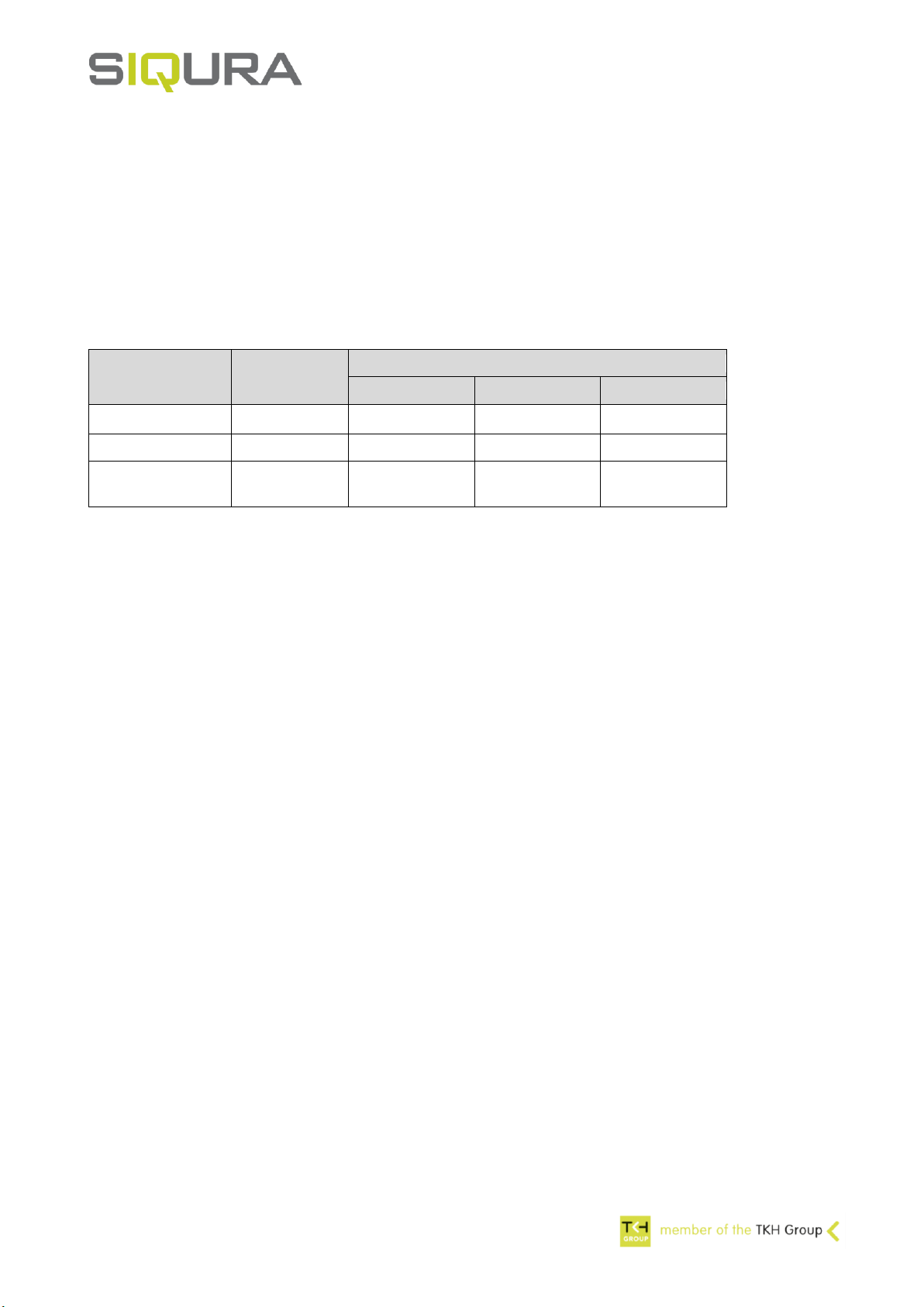
Power cable: maximum length table
Power supply
type
Total cable
resistance
Cable length for copper wire size
1.5mm²
0.75mm²
0.5mm²
24VAC 50/60Hz
< 1.2 Ohm
< 50m
< 25m
< 17m
24VDC
< 2.3 Ohm
< 100m
< 50m
< 33m
100 - 240VAC
50/60Hz
< 300m
< 150m
0.75mm²
minimum
Power cable: length and overvoltage protection
•The camera 24V power input is compliant with EMC standard EN 50130-4. This standard sets
requirements for surge voltage immunity in clause 13. The 24V power supply lines and signal lines are
tested for line-to-ground surge voltage levels up to 1kV (1.2/50 µs). There is no requirement for line-to-
line surge voltage testing on 24V inputs.
•The 24V power supply inputs may not be grounded.
•For cable lengths up to 10m no additional surge protection is recommended. For longer cables,
additional surge protection (SPD type T3 according IEC 61643, or equivalent) is recommended to
ensure that the camera overvoltage category (IEC 60664-1) is reduced to class II.
•The installer is required to provide additional protection to reduce the overvoltage if the equipment is
subject to transient overvoltages exceeding those for overvoltage category II.
Ethernet cable:
•Shielded CAT5E S/FTP, wire size AWG24, solid or stranded, cable length up to 100m.
•For PoE powering of the XCU cameras the Ethernet cable must comply with the IEEE 802.3at
requirements for PoE+ (up to 25,5W power at the camera). This means the maximum cable resistance
per pair set is limited to 12.5 Ohm. The recommended size AWG24 typically meets this requirement for
cable lengths up to 100m.
•For larger wire diameters the use of a junction box is recommended.

XCU Installation manual supplement -
Cables and connectors
Doc. ID: XCU Installation manual supplement - Safety, cables and connectors v5.docx
Authors: Wouter Hermelink, Peter de Konink
Page 4/5
Recommended connectors (Power and I/O)
•3p Conec power connector for 230V camera models. See product label for voltage range.
•3p Conec power connector for 24V camera models, without I/O.
•5p Conec power and I/O connector for 24V camera models, with additional relay contact outputs.
3p-Cable plug for power IP67 connector, size 7/8”
Conec Power (5p)
Part ID
CON CONEC PLUG POWER 3P IP67
599712000562 (Conec 41-00001)
Specifications
Pin assignment
IP67 rated only when covered with cap or mated
PE is connected to the metal camera housing
Cable range 6-12 mm (unshielded cable)
2 = (L) 230VAC or (+) 24VDC/24VAC
Screw termination, Wire range 0.5 –1.5 mm2
3 = (N) 230VAC or (-) 24VDC/24VAC
Temperature range -40°C to +85°C
UL approved E331608
Front view
5p-Cable plug for power IP67 connector, size 7/8”
Conec Power (5p)
Part ID
CON CONEC PLUG POWER 5P IP67
599712000622 (Conec 41-00003)
Specifications
Pin assignment
IP67 rated only when covered with cap or mated
1 = (+) 24VDC/24VAC
Cable range 6-12 mm (unshielded cable)
2 = (-) 24VDC/24VAC
Screw termination,
Wire range 0.5 –1.5 mm2
PE = Relay common for both relays.
PE is connected to the metal camera housing
Temperature range -40°C to +85°C
4 = Relay* ‘’I/O output 5” (normally open)
UL approved E331608
5 = Relay* ‘’I/O output 6” (normally open)
Front view
*Relay contact rating: 30V / 1A (AC or DC, resistive load)
XCU Installation manual supplement -
Cables and connectors
Doc. ID: XCU Installation manual supplement - Safety, cables and connectors v5.docx
Authors: Wouter Hermelink, Peter de Konink
Page 5/5
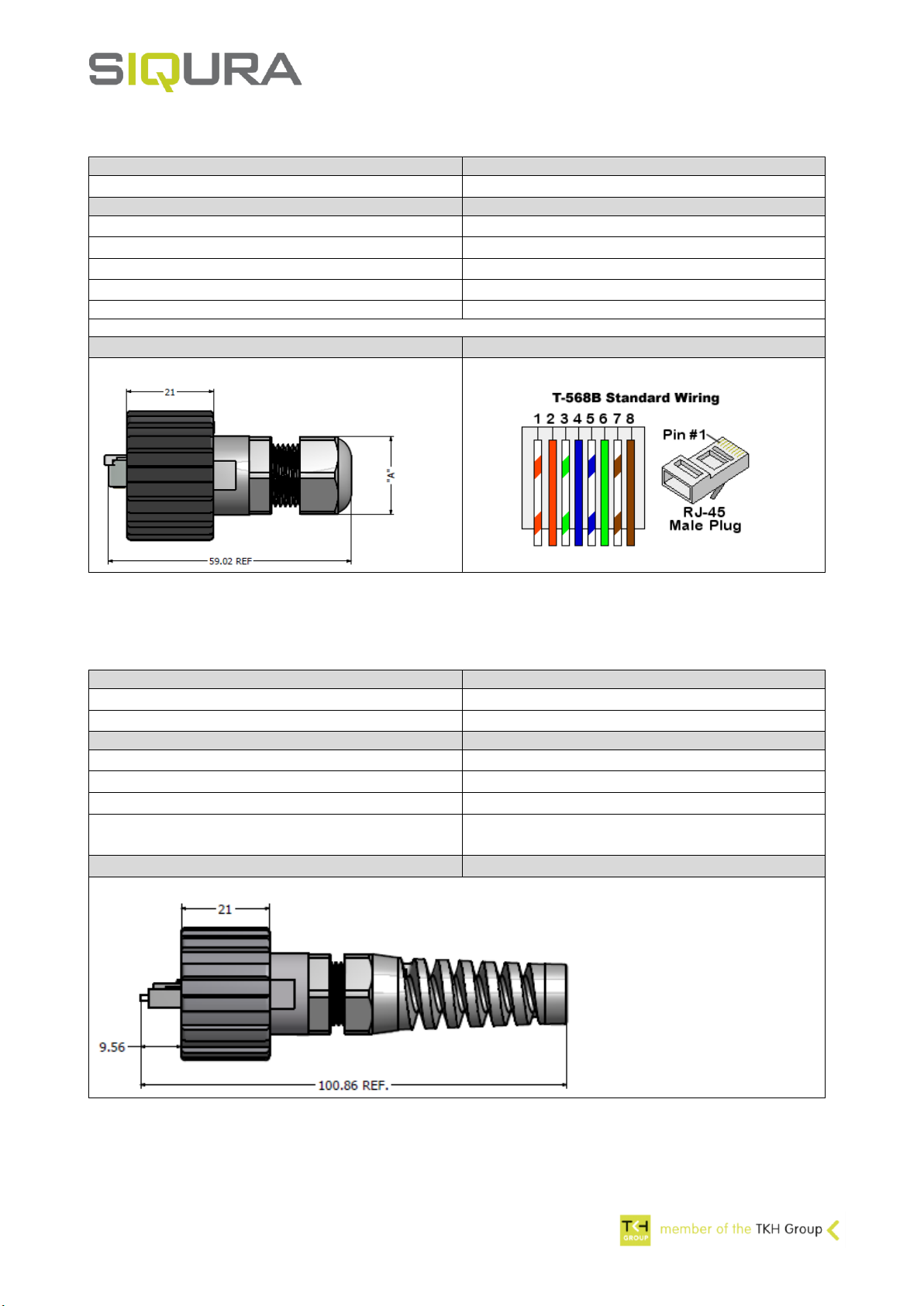
RJ45 IP67 plug kit, for CAT6A, AWG24
Conec RJ45 (8p)
Part ID
CON CONEC PLUG CAT6A IP67
599712000558 (Conec 17-150234)
Specifications
IP67 rated only when covered with cap or mated
Temperature range -40°C to +85°C
UL approved E202784
Cable range 4-8 mm (shielded cable)
Shielded CAT6A RJ45 plug (inside IP67 housing)
Wire size: solid or stranded AWG24
The RJ45 plug does not accept larger wire size.
Note: for wire size AWG27 up to AWG22 consider Conec 17-170004 (not tested by Siqura)
Side view
Plug shown is only used to indicate pin #1
Dual LC Plug for Fiber IP67 connector (Option: -2SM or -2MM)
Conec Dual LC Fiber
Part ID
CON CONEC PLUG DUAL LC SM IP67 With/CAP
599712000556 (Conec 17-300200)
CON CONEC PLUG DUAL LC MM IP67 With/CAP
599712000574 (Conec 17-300210)
Specifications
Color
IP67 rated only when covered with cap or mated
SM adapter = blue
Temperature range -40°C to +85°C
MM adapter = beige
UL approved E350510
Accept 4.5mm to 8.0mm outside diameter fiber
optic cable
Side view
This manual suits for next models
2
Table of contents
Other Siqura Digital Camera manuals


