Siqura S-64 E v2 User manual

S-64 E v2 / EVE
Firmware version 1.5.0
H.264 Video encoder series
User Manual

Note: To ensure proper operation, please read this manual thoroughly before using the
product and retain the information for future reference.
Copyright © 2015 Siqura B.V.
All rights reserved.
S-64 E v2 / EVE 1.5.0
User Manual v4 (141909-4)
AIT55
Nothing from this publication may be copied, translated, reproduced, and/or published by
means of printing, photocopying, or by any other means without the prior written permission
of Siqura.
Siqura reserves the right to modify specifications stated in this manual.
Brand names
Any brand names mentioned in this manual are registered trademarks of their respective
owners.
Liability
Siqura accepts no liability for claims from third parties arising from improper use other than
that stated in this manual.
Although considerable care has been taken to ensure a correct and suitably comprehensive
description of all relevant product components, this manual may nonetheless contain errors
and inaccuracies. We invite you to offer your suggestions and comments by email via
[email protected]. Your feedback will help us to further improve our documentation.
How to contact us
If you have any comments or queries concerning any aspect related to the product, do not
hesitate to contact:
Siqura B.V.
Zuidelijk Halfrond 4
2801 DD Gouda
The Netherlands
General : +31 182 592 333
Fax : +31 182 592 123
E-mail : [email protected]
WWW : www.siqura.com
2

Contents
1 S-64 E v2 / EVE Help ................................................................................. 5
2 S-64 E v2 at a glance ................................................................................. 6
3 Meet the EVE family .................................................................................. 7
4 Webpage features ..................................................................................... 9
5 Live Stream ............................................................................................... 11
6 Camera ..................................................................................................... 13
6.1 Camera Management ........................................................................... 13
6.2 Image Quality ..................................................................................... 14
6.3 Overlays ............................................................................................. 15
6.4 Streaming Profiles ............................................................................... 18
6.5 PTZ ................................................................................................... 21
6.6 Privacy Mask (S-64 E v2) ...................................................................... 22
7 Events ....................................................................................................... 24
8 Recording .................................................................................................. 25
9 Device ....................................................................................................... 27
9.1 Device Management ............................................................................. 27
9.2 Network ............................................................................................. 28
9.3 Date & Time ........................................................................................ 30
9.4 Security ............................................................................................. 32
9.5 User Management ................................................................................ 34
9.6 SNMP (S-64 E v2) ................................................................................ 35
10 Diagnostics ............................................................................................... 36
10.1 Logging .............................................................................................. 36
10.2 LED ................................................................................................... 36
11 Analytics ................................................................................................... 37
11.1 Motion Detection ................................................................................. 37
11.2 Tampering .......................................................................................... 38
11.3 Quality Monitor .................................................................................... 39
12 Advanced .................................................................................................. 40
12.1 Direct Streaming ................................................................................. 40
12.2 Data .................................................................................................. 41
12.3 Digital I/O .......................................................................................... 42
12.4 Audio ................................................................................................. 42
12.5 FTP .................................................................................................... 43
13 Troubleshooting ........................................................................................ 45
13.1 Date & Time issues .............................................................................. 45
13.2 FTP issues .......................................................................................... 45
13.3 Logon issues ....................................................................................... 45
13.4 Network issues .................................................................................... 46
3

13.5 PTZ issues .......................................................................................... 46
13.6 Upgrade issues .................................................................................... 47
13.7 Video issues ........................................................................................ 47
13.8 Webpage issues ................................................................................... 48
Acknowledgements ................................................................................... 49
Index ...................................................................................................... 50
Contents
4

1 S-64 E v2 / EVE Help
What this manual covers
This manual applies to Siqura's S-64 E v2 and EVE video encoder series. It provides the
context-sensitive Help that can be opened from the built-in webpages. The Help topics
explain:
● How to operate the unit
● How to adjust device settings
● How to manage user accounts
● How to resolve occurred issues
Note: When describing shared features, this manual uses the generic term "unit" to refer to
the S-64 E v2 and EVE encoders. In descriptions of distinguishing features, the individual
product names are used.
For installation and connection instructions, see the Quick Start Guide supplied with your unit.
Who should read this manual
This manual is written for engineers, administrators, operators and other users who are
involved in installing, operating or maintaining this unit.
What you should already know
When working with this unit, basic understanding and skills in the following fields are
recommended:
● Ethernet network technologies and Internet Protocol (IP)
● Windows environments
● Web browsers
● Video, audio, data, and contact closure transmissions
● Video compression methods
Why specifications may change
At Siqura, we are committed to delivering high-quality products and services. The information
given in this manual was current when published. As we continuously seek to improve our
products and user experience, all features and specifications are subject to change without
notice.
We like to hear from you!
Customer satisfaction is our first priority. We welcome and value your opinion about our
products and services. Should you detect errors or inaccuracies in this manual, we would be
grateful if you would inform us. We invite you to offer your suggestions and comments via
[email protected]. Your feedback helps us to further improve our documentation.
5
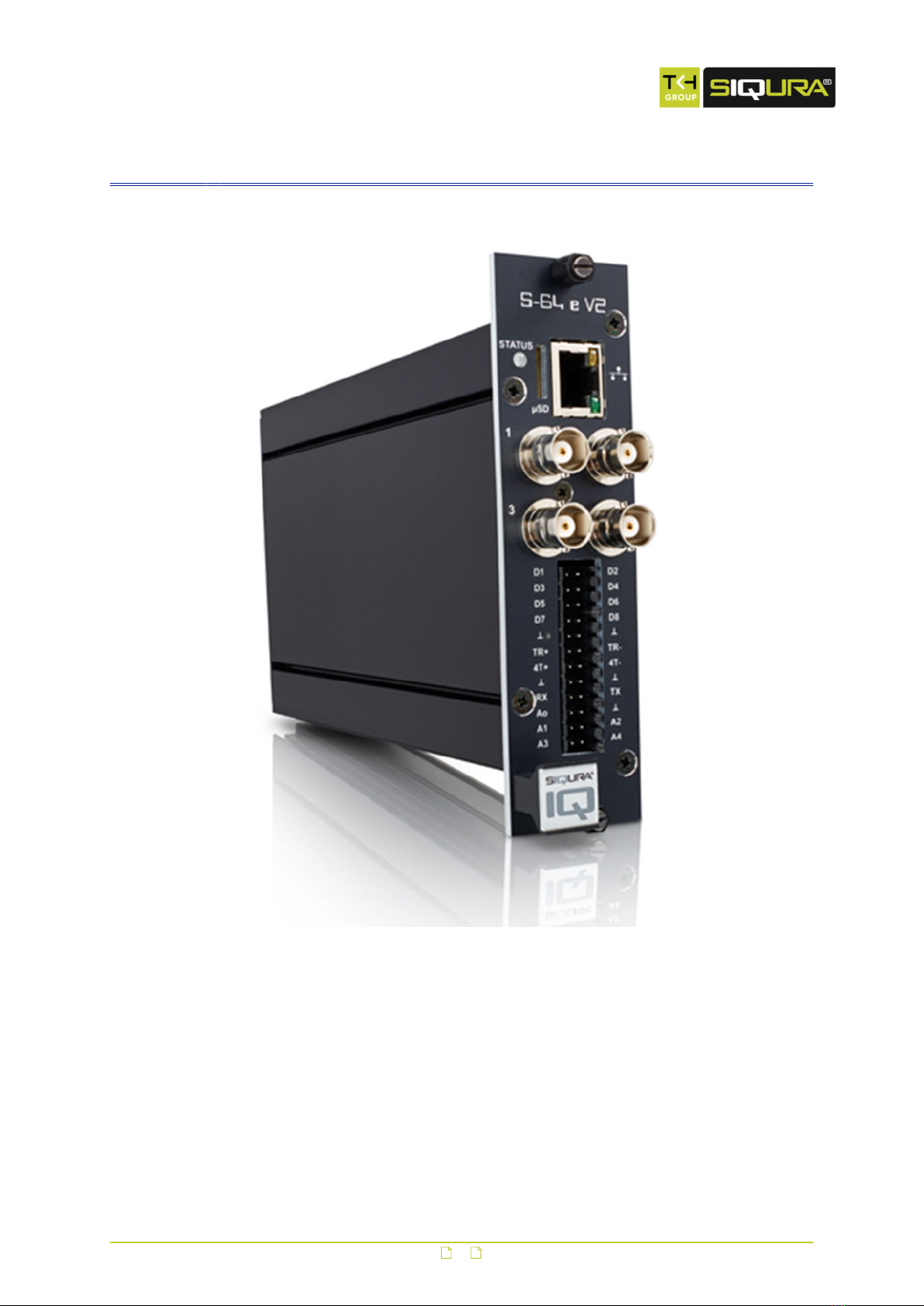
2 S-64 E v2 at a glance
S-64 E v2
● Four-channel H.264 video encoder
● ONVIF Profile S
● Edge recording
● Picture enhancement
● Image quality monitor
● Advanced tamper detection
● 960H Support
● Duplex serial data
● Open Streaming Architecture (OSA)
● Available with SFP interface
6
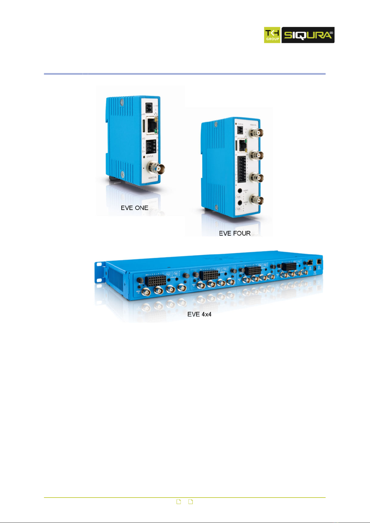
3 Meet the EVE family
EVE ONE
● One-channel H.264 video encoder
● Click & Go – compact DIN rail mounting
● 2x Digital I/O
● Edge storage on μSDHC card
● Available with Power over Ethernet (PoE)
EVE FOUR
● Four-channel H.264 video encoder
● Click & go: compact DIN rail mounting
● 8x Digital I/O
● 4x Audio in, 1x audio out
● Edge storage on μSDHC card
● Available with Power over Ethernet (PoE)
7

EVE 4x4
● Modular 4x four-channel H.264 encoder
● Edge storage on μSDHC card (4x)
● 4x 4 Audio in; 4x 1 audio out
● 4x 8 Digital I/O
EVE family shared features
● High resolution: 960 H support (960x576 pixels)
● Advanced picture enhancement
● Image quality monitoring
● Tamper detection
● ONVIF Profile S
Meet the EVE family
8
4 Webpage features
Siqura video encoders provide a built-in web server which makes it easy to access and
operate these products over the network.
Browser-based access
Using a standard web browser on a PC with an IP connection to the unit, you can open the
Live Stream page and view live video from one or more connected cameras. Users with
appropriate permissions can also open the configuration pages to manage the unit's device
and user settings. Siqura encoders support the latest two versions of Chrome, Internet
Explorer, Firefox, and Safari.
Menu
Use the vertical menu on the left to navigate the webpages of the unit. Clicking an entry
opens the associated page or a submenu.
Tip: To find a specific webpage quickly, type its name in the search-as-you-type box above
the menu.
Page layout
Webpage layout is single-page or content is organised across multiple tabs located at the top
of the page. When clicked, each tab shows related commands and settings. The active tab is
identified by its highlighted and underlined title.
Camera preview
Pages such as Live Stream, Overlays, Motion Detection, and Tampering include a camera
preview. You use it to view live video or determine the effect of your settings when making
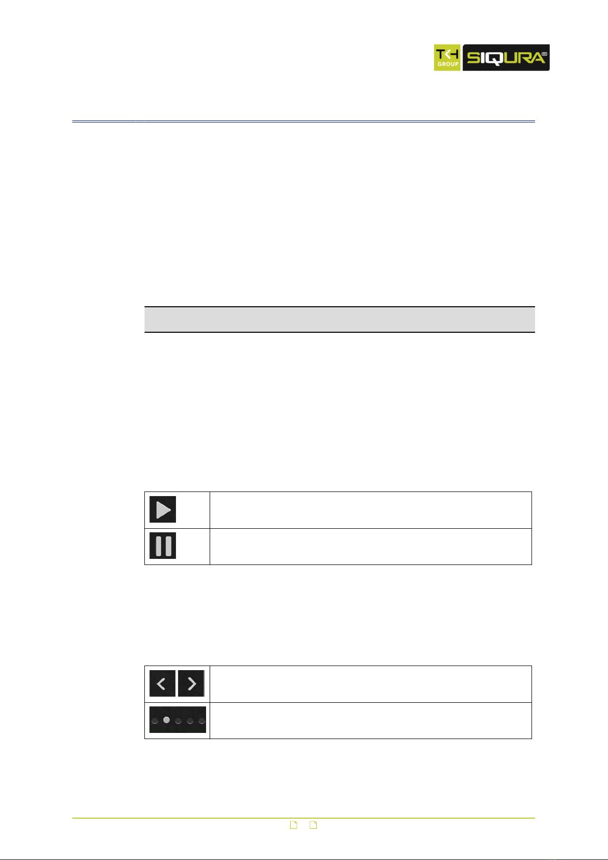
changes for specific functions. Click the Play/Pause buttons in the centre of the preview to
control video streaming. To display these buttons when hidden, move the mouse pointer over
the preview pane.
Play live video stream
Pause live video stream
Switch camera (multichannel units)
The Live Stream page on multichannel units is opened in matrix mode, displaying a two-by-
two grid with images from all connected cameras. An individual camera view can be selected
and brought to the foreground by clicking the buttons that appear when you move the mouse
pointer over the previews.
Show the previous/next camera view.
Show the camera view associated with this option button.
9

Revert button
The Revert button appears when you adjust specific settings. You can use it to undo your
changes. The button is available until you leave the webpage.
Restore the setting to its original state (at the time of opening the
webpage).
Webpage features
10

5 Live Stream
On the Live Stream page, you can view live video from one or more connected sources. If the
source is a PTZ camera, you can operate this camera if it supports the driver selected on the
PTZ page (see "PTZ" on page 21).
Preview layout
On successful connection to the unit, the Live Stream page is opened, showing:
● A single-camera preview (one-channel units)
● A 2x2 video matrix (multichannel units)
View live video
Video is paused when you open the Live Stream page.
1 Move your mouse pointer over the preview pane.
2 In the centre of the preview pane, click Play.
Streaming video from the connected source(s) is displayed.
Video streaming can be stopped with Pause.
Maximised mode (multichannel units)
You can enter maximised mode to bring a preview to the foreground.
1 Move your mouse pointer over the preview pane.
2 Click the Next/Previous buttons (see "Webpage features" on page 9) to select the
preview you want to maximise.
For direct access, you can click the appropriate camera button at the bottom of the
preview pane.
This enlarges the preview and hides the other images.
Full-screen mode
For better observation, you can enter full-screen mode.
1 In the upper-right corner of the preview pane, click Full-screen.
The preview pane now fills your entire screen.
2 To return to the previous mode, click Close full-screen or press Esc on your keyboard.
Use your browser for PTZ control
A PTZ camera connected to the unit can be controlled from your web browser.
Note: First go to the PTZ page (see "PTZ" on page 21) to activate a PTZ driver which is
supported by the camera.
With the driver activated, you can operate the camera from the Live Stream page.
1 On multichannel units, click the Next/Previous buttons to select the camera you wish
to control.
2 In the upper-right corner, click Show PTZ controls.
A yellow circle appears in the centre of the preview.
3 To position the camera, drag the highlighted dot across the circle in the direction you
need.
It is also possible to move the camera by clicking in the circle.
4 To adjust Zoom, Focus, and Iris as needed, drag the corresponding sliders.
5 To save a camera position as a preset, click the Favourites button, Store current
position as preset.
11

6 To recall a preset camera position, click Select, and then click the required preset.
7 To delete a selected preset, click the Recycle button, Delete preset.
Note that a deleted preset is irretrievably lost! You are therefore asked to confirm the
deletion.
More preset management functions are available on the PTZ page (see "PTZ" on
page 21). There, you can rename presets, add reserved presets, and delete multiple
presets in one go.
Take a snapshot
It is possible to take a snapshot of the camera preview(s) on the Live Stream page.
● In the upper-right corner, click Take snapshot.
The picture is saved in JPG format to your Downloads folder.
The file name includes the camera name and date/time information.
Record a live stream
You can record the video on the Live Stream page to your PC. The names of the AVI format
files include date and time information to identify the recordings.
1 In the upper-right corner, click Start recording.
The record button flashes red to show that you started a recording.
2 To stop the recording, click Stop recording.
Your browser can now download the recording.
Live Stream
12

6 Camera
Per channel, the unit can take an input signal from an analogue camera and convert it to two
digital video streams. On the webpages grouped under Camera, you can adjust video
streaming, image quality, and camera management settings.
In This Chapter
6.1 Camera Management.............................................................................................13
6.2 Image Quality...................................................................................................... 14
6.3 Overlays.............................................................................................................. 15
6.4 Streaming Profiles.................................................................................................18
6.5 PTZ.....................................................................................................................21
6.6 Privacy Mask (S-64 E v2)....................................................................................... 22
6.1 Camera Management
On the Camera Management page, you can assign a camera name and select the aspect ratio.
On S-64 E v2 encoders, you can also enable/disable the video input, set the input impedance,
and select a video standard.
Name
Type a descriptive name in the Name box. This makes the camera easily identifiable on the
network. Preferably, use a unique name, one that includes the physical location, for example.
The name you give here can be displayed as an overlay (see "Overlays" on page 15) over
the camera images. When the overlay is enabled, the camera name is visible in the webpage
previews in your browser and in the video streams transmitted by the unit.
Input
A video input is enabled by default. You can choose to set this input to Disabled. This is
typically done when no video signal is connected to an input.
If you disable the input:
● No “Video loss”, “Image quality” and “Tamper detect” alarms will be raised.
● The blue screen with “No Video” will not be shown when no input signal is connected.
● A black image with reduced frame rate with only the OSD-texts will be streamed.
Aspect ratio
The aspect ratio determines the proportional relationship between the width and height of the
video images. As different cameras may stream differing video standards, you may want to
adjust the aspect ratio for optimal image display.
1 Click the Aspect ratio list.
2 Select 4:3 (standard aspect ratio) or 16:9 (wide-screen).
Input impedance (S-64 E v2)
Impedance is the measure of resistance to signal current flow. With one video source on one
video input, select 75 Ohm. With a number of video inputs in parallel using one video source,
use High-Z on all inputs except the last.
13

Video standard (S-64 E v2)
This video display standard you select here - PAL, NTSC, or Auto - determines the available
frame rates on the Streaming Profiles page - that is 25 fps for PAL and 30 fps for NTSC.
6.2 Image Quality
On the Image Quality page, image quality settings are overlaid over the video shown in the
camera preview. Use these settings to enhance the image quality for optimal display in your
web browser or in an application you are using to extract the video stream. Any changes you
make are immediately effective and visible in the preview.
Note: On multichannel units, the settings on this page can be adjusted per individual
camera. Select the intended camera by clicking the Next/Previous buttons as needed, and
then make the required changes.
Noise filter
It is possible to (partially) remove noise from the video signal.
1 Click the Noise filter list.
2 Select Weak, Average, or Strong as required.
Selecting Off disables the filter.
Auto-enhancement
When set to On, this function continuously analyses the images and dynamically adjusts the
image quality to compensate for changing conditions.
Manual enhancement
Image quality can be controlled manually.
1 Set Auto-enhancement to Off.
2 While observing the changes in the preview, move the Brightness, Colour saturation,
Contrast, Hue, and Sharpness sliders until you achieve optimal viewing quality.
Note: With manual enhancement, the settings are not dynamically adjusted when conditions
change.
Brightness
Use this function to adjust the brightness level of the video images to your viewing conditions.
Colour saturation
Use this function to adjust the intensity (purity) of the colours in the video images.
Contrast
Use this function to adjust the contrast level of the video images to your viewing conditions.
Hue
Use this function to enhance the colours in the video images if they do not look natural.
Sharpness
Use this function to adjust image sharpness to your viewing conditions.
Camera
14

6.3 Overlays
It is possible to add independently configurable text lines to the video signal for on-screen
display (OSD) purposes. On S-64 E v2 units, you can also add a graphical image.
Note: On multichannel units, the settings on this page can be adjusted per individual
camera. Select the intended camera by clicking the Next/Previous buttons as needed, and
then make the required changes.
Product Text lines Graphic
EVE ONE, EVE FOUR, EVE 4x4 2x N/A
S-64 E v2 3x 1x
Overview
The Overlays page has the following tabs:
●Overlay management
Use this tab to add and delete text lines and a graphical image (S-64 E v2). You can
position the objects over the video image and determine their appearance.
●Font management
Use this tab to select, add, and delete fonts.
●Image management (S-64 E v2)
Use this tab to select, add, and delete a graphical image.
Overlay management buttons
Overlays are created on the Overlay management tab. The Add text overlay and Add
image overlay (S-64 E v2) buttons open a dialogue box with overlay settings.
Camera
15

Button Name Button Available settings
Add text overlay Insert text and set the render
mode
Position the text overlay over
the video image
Set font colour, border
colour, and transparency
Select font and set font size
Delete overlay
Add image overlay
(S-64 E v2)
Select a picture for the
overlay
Position the overlay picture
over the video image
Set transparency, scaling,
and animation speed
Delete overlay
Add a text overlay
Overlays are created independently of each other.
1 Click Add text overlay.
A dialogue box pops up. It has a toolbar with four buttons. The active button is
highlighted in green.
2 In the Text box, type the text that is to be displayed on-screen.
- or -
Click the button next to the Text box, and then select the entry to be inserted.
It is possible to reopen the list and click a different entry to append to the selection
already in the Text box.
3 In the Render mode list, select Outline or Border as needed.
Your settings are immediately effective. See the preview for visual feedback.
4 Click the Position button.
5 In the Position list, select a preset position.
- or -
Click Free positioning, and then use the X position and Y position sliders or boxes to
freely position the object over the video image. Using the Anchor point setting, you
can shift the object relative to the anchor point.
6 Use Rotation angle to rotate the text.
7 Click the Colour button, select the font colour and border colour, and then set the
transparency of the text overlay.
8 Click the Font button, select the font to be used, and then enter the font size.
Fonts can be uploaded via the Font management tab.
Camera
16

Add an image overlay (S-64 E v2)
You can create one image overlay.
1 Click Add image overlay.
A dialogue box pops up. It has a toolbar with three buttons. The active button is
highlighted in green.
2 Click the Image list.
3 Select the image for the overlay.
You can add images to the list via Image management. The S-64 E v2 / EVE
supports .GIF and .JPG images.
4 Click the Position button.
5 In the Position list, select one of the preset positions.
- or -
Click Free positioning, and then use the X position and Y position sliders or boxes to
freely position the object over the video image. Using the Anchor point setting, you
can shift the object relative to the anchor point.
6 Click the Advanced button.
7 Set the transparency and scaling of the image overlay with the appropriate sliders or
text boxes.
8 If your overlay is an animated GIF graphic, define its speed in the Animation speed
text box.
Delete an overlay
1 On the Overlay management tab, click on the overlay.
2 In the dialogue box, click the recycle button, Delete overlay.
Font management
Fonts for text overlays can be uploaded to the unit. This is done on the Font management tab
where you can also delete fonts that are no longer needed.
Upload a font
1 Click Upload font.
2 Drag the font file onto the dashed rectangle.
3 Click Upload.
Delete a font
1 Click Select font to delete.
2 In the Font list, select the font to delete.
3 Click Delete.
Image management (S-64 E v2)
Images that you want to use for graphical overlays can be uploaded to the unit. This is done
on the Image management tab where you can also delete images which are no longer
needed.
Upload an image
1 Click Upload image.
2 Drag the image file onto the dashed rectangle.
The unit supports .GIF and .JPG files.
3 Click Upload.
Delete an image
1 Click Select image to delete.
Camera
17

2 In the Image list, select the image that you want to delete.
3 Click Delete.
6.4 Streaming Profiles
Dual streaming
The unit can take the analogue video signal from a connected camera and convert it into two
independent digital video streams with different video encoding settings.
Streaming profile types
A straightforward method of configuring the encoding settings for a video stream is to use a
factory-set streaming profile - that is, a predefined combination of settings for a specific
application. The unit offers profiles optimised for video storage, PTZ, or high-quality live
viewing, for example. If none of the factory profiles meets your requirements you can create
and save user-defined streaming profiles.
Use a factory-set profile
A factory-set streaming profile defines the settings that the unit will use for the specific
application.
1 Click the camera name at the top of the webpage.
2 Click Stream 1 or Stream 2 to select the stream to assign the streaming profile to.
3 In the Profile list below the camera name, select the factory profile which is appropriate
for the intended purpose.
4 Repeat steps 1 through 3 for the other stream, if necessary.
Factory profile settings
After you select a factory profile, the video stream is encoded using the associated settings
shown below the profile list. For several settings, the webpage also shows the actual value to
the right of the defined value.
Create a custom profile
If the supplied factory-set profiles do not meet your requirements you can create a custom
streaming profile.
1 Click the camera name at the top of the webpage.
2 Click Stream 1 or Stream 2, to select the stream to assign the streaming profile to.
3 In the Profile list, select the factory profile to be used as a basis for the custom profile.
4 Adapt the profile settings to your requirements.
The custom profile is added to the Profile list (User section) as: Factory profile-Copy-
yymmdd.
5 To rename the profile, type a descriptive name into the Name box.
Delete a custom profile
Custom streaming profiles can be deleted (unlike factory-set profiles).
1 In the Profile list, select the profile to be deleted.
2 Click Delete.
3 In the information bar, click Yes, delete to confirm this action.
Name
Indicates the currently selected streaming profile. You can name and rename custom
streaming profiles. The names of the factory-set profiles cannot be changed.
Camera
18

Encoder type
Depending on the application, select the video encoding method that is to be used to
compress the analogue video signal.
Frame rate
Here you can set the number of video frames per second for the video transmission. Range:
1-25 fps (PAL); 1-30 fps (NTSC).
GOP size
Determines the distance in frames between two I-frames.
Maximum bit rate
Here you can set the maximum bit rate allowed for the video transmission. You can use this
setting to control the network load. The actual bit rate is shown to the right of the text box.
This value is dynamically updated with the current bit rate to provide feedback on the bit rate
that is used on average with the current Maximum quality setting. This setting corresponds
with Constant Quality Mode or Variable Bit Rate.
Maximise long term bit rate
The default setting is not very suited for recording and storage, the total amount of data
needed is unpredictable. This mode defines the average bit rate for a period of time. This
mode corresponds with a type of Constant Bit Rate.
Select Enable to display and activate the Max. long term bit rate parameter. Clear the check
box to deactivate and hide that parameter.
Max. long term bit rate
With this setting you can optimise the bit rate by specifying an average value allowed for a
longer period.
Maximum quality
Generally speaking: the higher the Maximum quality setting, the lower the compression ratio
and the more bits are consumed. This means a trade-off has to be found between the desired
quality level and available bandwidth. When configuring these settings it is good to keep the
following in mind.
● If the configured Maximum quality cannot be achieved with the currently set Maximum bit
rate, the actual quality will be lower. The actual quality percentage is shown real-time to
the right of the configured Maximum quality.
● The actual quality level will never exceed the configured Maximum quality, even if the
Maximum bit rate should allow it.
Resolution
Indicates the number of pixels that can be displayed in each dimension (width x height). See
the table below for supported resolutions.
Camera
19

PAL NTSC
960H 960x576 960x480
D1 720x576 720x480
2/3 D1 480x576 480x480
1/2 D1 352x576 352x480
4CIF 704x576 704x480
2CIF 720x288 720x240
CIF 352x288 352x240
QCIF 176x144 176x120
VGA 640x480 640x480
QVGA 320x240 320x240
Traffic shaping (S-64 E v2)
Traffic shaping sets the maximum network bit rate per encoder. Traffic shaping will spread
network traffic bursts which helps the network infrastructure handle the traffic. In its turn,
however, traffic shaping will increase the latency.
● With traffic shaping set to Off, the stream is transmitted with minimum latency but with
bursty network traffic.
● With traffic shaping set to High, the network traffic is evenly spread out in time, but the
latency will increase.
Parameter value combinations
When you create a custom streaming profile, set sensible combinations of Frame rate, GOP
size, Maximum bit rate, Maximum long term bit rate, Maximum quality, and Resolution. If in
doubt about the effects of specific encoder settings, you are advised to select the factory-set
profile offering the closest match to your required application.
Use Quad view (S-64 E v2)
To see live video from the S-64 E v2, you can use a web browser or video viewing software.
In a browser, the Live Stream page presents the four camera views arranged in quad layout.
For closer viewing, you can select an individual camera. Likewise, if you use viewing software
to extract video, you can request a quad view RTSP stream or open a separate RTSP stream
per channel. Note that the unit's Quad view function is disabled by default.
1 On the Quad view tab, click Enable.
2 Configure the encoding settings as needed.
3 In your viewing application, specify the URL containing the IP address of the S-64 E v2.
4 Add "/quad" after the IP address.
For example: rtsp://10.50.3.72/quad
On successful connection, the S-64 E v2 quad view is streamed to your application.
Tip: Depending on the chosen settings, the overall performance will be reduced when the
quad view stream is enabled. To prevent reduced frame rate or increased latency, it is
recommended to set any unused streams to low resolution and low frame rate.
Camera
20
Other manuals for S-64 E v2
1
This manual suits for next models
3
Table of contents
Other Siqura Media Converter manuals


Popular Media Converter manuals by other brands


POSITAL
POSITAL KCD-BCX3B 17 Series Installation leaflet

Xantech
Xantech RF2IR2W quick start

Tascam
Tascam CD-A580 Getting started

Network Electronics
Network Electronics Flashlink HD-EO-2 user manual

AJA
AJA HA5-Fiber Installation and operation guide

Fairport
Fairport FBS40M Operation, spare parts and service manual


