Sirius Fitness 16117002LUS User manual
Elliptical
OWNER`S
MANUAL
Model No.
16117002LUS
Sirius Fitness
Elliptical
Trainer
Assembly
Operation
Exercise
Parts
Warranty
Retain for Future reference
CAUTION: You must read and understand this owner’s manual before operating unit.

Customer Service 1-888-707-1880
1
Manufacture’s One-Year Limited Warranty
Your Sirius Fitness Elliptical trainer is warranted for one year from the date of purchase
against defects in material when used for the purpose intended, under normal conditions and
provided it receives proper care. Any part found defective or missing will be sent at no cost
when returned in accordance with the terms of this warranty.
This warranty is not transferable and is extended only to the original owner.
The warranty shall not apply to exercise units which are (1) used for commercial or other
income producing purposes, or (2) subject to misuse, neglect, accident or unauthorized
repair and alterations.
This warranty provided herein is lieu of all other express warranties, any implied warranties,
including any implied warranties of merchantability of fitness for particular purpose, are
limited in duration to the first 12 months from date of purchase. All other obligations or
liabilities, including liability for consequential damages are hereby excluded.
REPAIR PARTS AND SERVICE
All of the parts for the elliptical shown in figure can be ordered from Dyaco Canada Inc.
6050 DON MURIE STREET, NIAGARA FALLS, ONTARIO L2G 0B3. When ordering parts,
the parts will be sent and billed at the current prices. Prices may be subject to change without
notice. Check or money order must accompany all orders. Standard hardware items are
available at your local hardware store.
To ensure prompt and correct handling of any errors, or to answer any questions, please call
our Toll Free number: 1-888-707-1880, or local number 1-905-353-8955 or fax 1-905-353-
8:30 AM to 5:00 PM Monday to Friday Eastern Standard Time.
Always include the following information when ordering parts
Model number
Name of each part
Part number of each part
TABLE OF CONTENTS
WARRANTY 1 MONITOR INSTRUCTIONS 14-15
SAFETY PRECAUTIONS 2-3 TROUBLE SHOOTING 16
HOW THE ELLIPTICAL WORKS 3 GETTING ON/OFF YOUR ELLIPTICAL 17-18
PRE-ASSEMBLY CHECK LIST 4 HOW TO ADJUST THE RESISTANCE
OF THE PEDALS 19
HARDWARE PACKING LIST 5 HOW TO ADJUST THE DRIVE BELT 20
ASSEMBLY INSTRUCTION 6-9 TRAINING GUIDELINES 21-23
DIAGRAM & PARTS LIST 10-13 STRETCHING 24-25

Customer Service 1-888-707-1880
2
SAFETY PRECAUTIONS
Thank you for purchasing our product. Even though we go to great efforts to ensure the
quality of each product we produce, occasional errors and/or omissions do occur. In any
event should you find this product to have either a defective or a missing part please contact
us for a replacement.
This product has been designed for home use only. Product liability and guarantee conditions
will not be applicable to products being subjected to professional use or products being used in
a gym centre.
This exercise equipment was designed and built for optimum safety. However, certain
precautions apply whenever you operate a piece of exercise equipment. Be sure to read the
entire manual before assembly and operation of this machine. Also, please note the following
safety precautions:
1. Read the OWNER’S OPERATING MANUAL and all accompanying literature and
follow it carefully before using your elliptical.
2. If dizziness, nausea, chest pains, or any other abnormal symptoms are experienced
while using this equipment, STOP the workout at once. CONSULT A PHYSICIAN
IMMEDIATELY.
3. Inspect your exercise equipment prior to exercising to ensure that all nuts and bolts are
fully tightened before each use.
4. The elliptical must be regularly checked for signs of wear and damage. Any part found
defective, the part must be replaced with new spare part from the manufacturer.
5. Fitness equipment must always be installed on a flat surface, do not place the unit on
a loose rug or uneven surface. It is recommended to use an equipment mat to prevent
the unit from moving while it is being used, which could possibly scratch or damage
the surface of your floor.
6. No changes must be made which might compromise the safety of the equipment.
7. It is recommended to have a minimum of 2’ safe clearance around the exercise
equipment while in use.
8. Keep children and pets away from this equipment at all times while exercising.
9. Handicapped individuals should have medical approval and close supervision when
using this elliptical.
10. Do not place hands or feet under the elliptical. Always keep hands and legs off of the
elliptical when others are using it.
11. Always hold the handlebars when mounting, dismounting, or using the elliptical. Keep
your back straight when using your elliptical; do not arch your back. When you stop
exercising, allow the pedals to slowly come to a complete stop. The elliptical does not
have a free wheel; the pedals will continue to move until the flywheel stops.
12. Use the elliptical only for its intended use as described in this manual. Do not use any
attachments that are not recommended by the manufacturer.
13. Never allow more than one person on the elliptical at once.
14. The pulse sensor is not a medical device. Various factors, including the user’s
movement, may affect the accuracy of heart rate readings. The pulse sensor is
intended only as an exercise aid in determining heart rate trends in general.
15. Start slowly and very gradually increase your speed and distance.
16. Warm up 5 to 10 minutes before each workout and cool down 5 to 10 minutes
afterward.
This allows your heart rate to gradually increase and decrease and will help prevent
you from straining muscles.
17. Never hold your breath while exercising. Breathing should remain at a normal rate in
conjunction with the level of exercise being performed
18. Always wear suitable clothing and footwear while exercising. Do not wear loose fitting
clothing that could become entangled with the moving parts of your elliptical.
19. Care must be taken when lifting or moving the equipment, so as not to injure your back.
Always use proper lifting techniques
20. User weight should not exceed 250lbs.
Customer Service 1-888-707-1880
3
21. Decal is found on the frame of the elliptical. If decal is missing, not legible or damaged
please call toll free -1-888-707-1880 for replacement decal.
22. This elliptical is intended for in-home use only. Do not use the elliptical in any
commercial, rental or institutional setting.
▲WARNING: Before beginning any exercise program consult your physician. This is
especially important for individuals over the age of 35 or persons with pre-existing
health problems. Read all instructions before using any fitness equipment. We
assume no responsibility from personal injury or property damage sustained by or
through the use of this product.
SAVE THESE INSTRUCTIONS
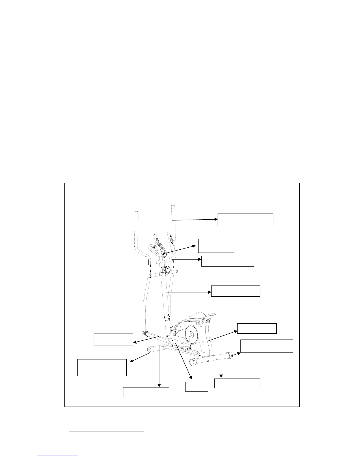
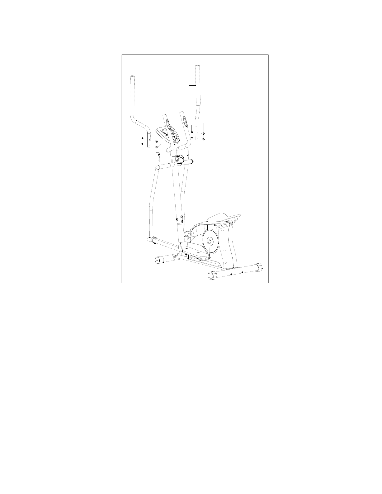
HOW THE ELLIPTICAL WORKS
The elliptical allows your feet to move in a natural elliptical path, minimizing the impact on your knees
and ankles.
The elliptical provides smooth, quiet and variable exercise capabilities with:
Dual Action Handles for total body workout
Stationary handlebar for stability
Moving Handlebar
Safety Handlebar
Computer
Handlebar Post
Chain Cover
Pedal Tube
Transportation
W
heel
Front Stabilizer
Rear Stabilizer
Leveling End Cap
Pedal
Customer Service 1-888-707-1880
4
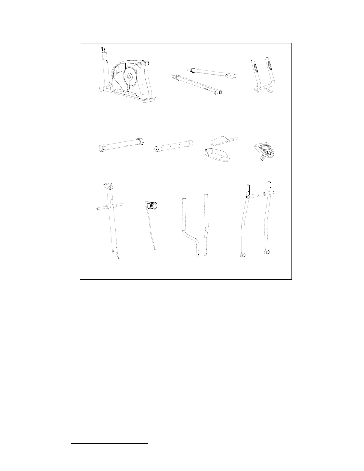
PRE-ASSEMBLY CHECK LIST
NO:1
NO:2 NO:3
NO:22
NO:9L/R NO:39
NO:13L/R NO:38
NO:37L/R NO:21L/R
NO:25
PART NO. DESCRIPTION Q’TY
1 Main frame 1
2 Rear stabilizer 1
3 Front stabilizer 1
9 L / R Pedal tube left / right 1 / 1
13 L / R Pedal left / right 1 / 1
21 L / R Bottom handlebar left / right 1 / 1
22 Upright 1
25 Tension knob w/upper tension cable 1
37 L / R Top handlebar left / right 1 / 1
38 Monitor 1
39 Stationary handlebar 1
Hardware bag 1
Manual 1
Customer Service 1-888-707-1880
5
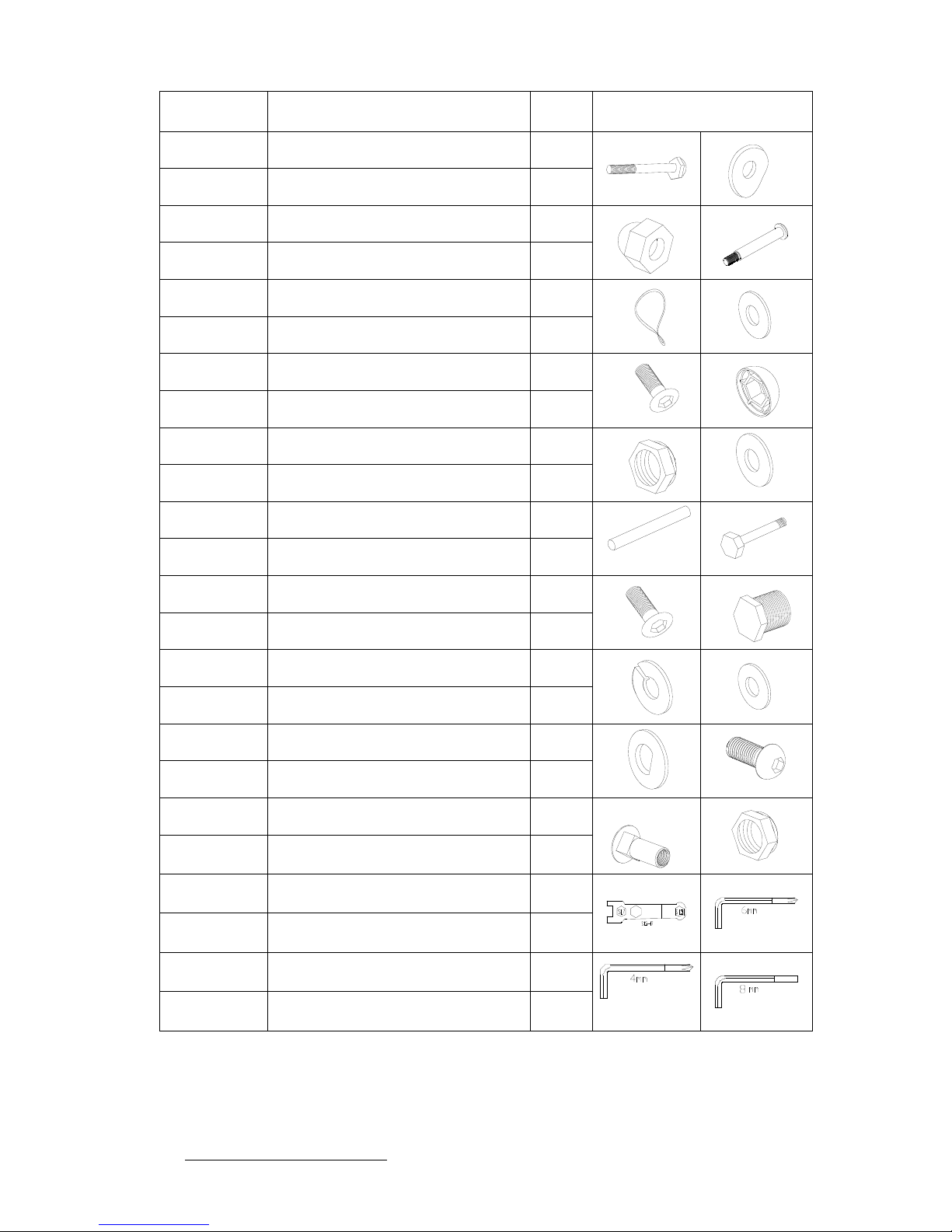
HARDWARE PACKING LIST
Part NO Description Q’ty Drawings
6 Carriage bolt M8*60 4
7 Curved washer Φ8*Φ20*1.5 10
8 Domed nut M8 4
10 L / R Hinge bolt left / right 1 / 1
11 Wave washer 2
12 Flat washer 2
14 Carriage bolt M10*45 4
15 PVC cap 6
16 Nylon lock nut M10 6
17 Washer Φ22*Φ10*1.5 6
18 Sleeve 2
20 Hex head bolt M10*65 2
23 Allen screw M8*16 6
29 Hex head bolt M10*20 2
30 Spring washer φ10 2
31 Flat washer Φ32*Φ10*1.5 2
32 D type washer 2
35 Allen screw M6*12 4
36 Carriage bolt M6*20 4
51 L / R Nylon lock nut left / right 1 / 1
69 Allen wrench S13,17 2
70 Allen key 6mm 1
71 Allen key 4mm 1
72 Allen key 8mm 1

Customer Service 1-888-707-1880
6
ASSEMBLY INSTRUCTION
This manual is designed to help you easily assemble, adjust and use this machine. Please read this
manual carefully. For the sake of familiarizing yourself with the parts identified in the instruction, first
study the overview drawing.
Set all parts in a clear area on the floor and remove the packing material. Refer to the parts list for
help to identify the parts.
It will take two people to assemble your unit.
STEP 1
Attach the front stabilizer (3) to the main frame (1), securing with two carriage bolts (6), two
washers (7) and two domed nuts (8).
Attach the rear stabilizer (2) to the main frame (1), securing with two carriage bolts (6), two
washers (7) and two domed nuts (8).
1
2
3
6
67
7
7
7
8
8
8
8
STEP 2
Insert the upper tension cable (25) into the hole of the upright (22), secure by using one bolt (50)
and one flat washer (49) on the back of the upright (22).
Connect the cable from the tension control (25) to the lower tension cable (27).
Connect the extension sensor wire (26) to the sensor wire (28).
Insert the upright (22) into the main frame (1) and secure using four allen screws (23) and four
curve washers (7).
Note: Be careful not to pinch the wires when you tighten the bolts.
2827
7
7
22
23
23
25
26
49
50
1

Customer Service 1-888-707-1880
7
STEP 3
Attach the left bottom handlebar (21L) to the left axle of the upright (22). Secure using D type
washer (32), one flat washer (31), one spring washer (30) and one hex head bolt (29). Attach the
PVC cap (15) onto the hex head bolt (29).
Repeat for the right bottom handlebar (21R).
15
21L
29
30
31
32
15
21R
29
31
32
30
1
22
STEP 4
Attach the left pedal tube (9L) to the left bottom handlebar (21L). Slide the sleeve (18) into the
left pedal tube (9L) and the left bottom handlebar (21L). Secure using one hex head bolt (20),
one washer (17), one nylon lock nut (16) and two PVC caps (15).
Repeat for the right side.
Attach the left pedal tube (9L) to the left side of the crank arm (24). Secure using one left hinge
bolt (10L), one wave washer (11), one flat washer (12) and one nylon lock nut (51L).
Repeat for the right side.
9L
10L
11 12
15
15
16
17
18
20
51L
24
1
21L
22

Customer Service 1-888-707-1880
8
STEP 5
Attach the stationary handlebar (39) to the back of the upright (22). Secure using two allen
screws (23) and two curve washers (7).
Remove the grommet (47) form the upright (22) and insert the hand pulse wires (46) through the
grommet (47) and slide up through the opening of the upright (22).
STEP 6
Connect the pulse wires from the monitor (38) to the pulse wires (46).
Connect the sensor wire from the monitor (38) to the extension sensor wire (26).
Attach the monitor (38) to the top of the upright (22) and secure using four screws (48) which
were pre-assembly on the computer.
Note: Ensure that the wires are away from the bracket when sliding onto the computer.
Attach the Left Pedal (13L) to the left pedal tube (9L) and secure using two sets of carriage bolts
(14) , washer (17) and nylon lock nut (16) .
Noted: The pedal position is optional. Normally, please attach the pedal by first two holes. If you
attach the pedal by last two holes, please don’t touch the crank & chain cover by fingers during
exercise.
Repeat for the right pedal (13R).
46
26
1
38
13R
13L
14
17
16
17
16
14
47
1
7
23
46
39
22
Customer Service 1-888-707-1880
9
STEP 7
Attach the left top handlebar (37L) to the left bottom handlebar (21L) and secure using two allen
screws (35) and two carriage bolts (36).
Repeat for the right top handlebar (37R).
37L
36
35
35 36
37R
NOW FIRMLY TIGHTEN ALL NUTS AND BOLTS
YOUR UNIT IS NOW FULLY ASSEMBLED
Your elliptical is equipped with adjustable end caps.
If the unit is wobbly, please turn the leveling caps on
the rear stabilizer to level the unit.

Customer Service 1-888-707-1880
10
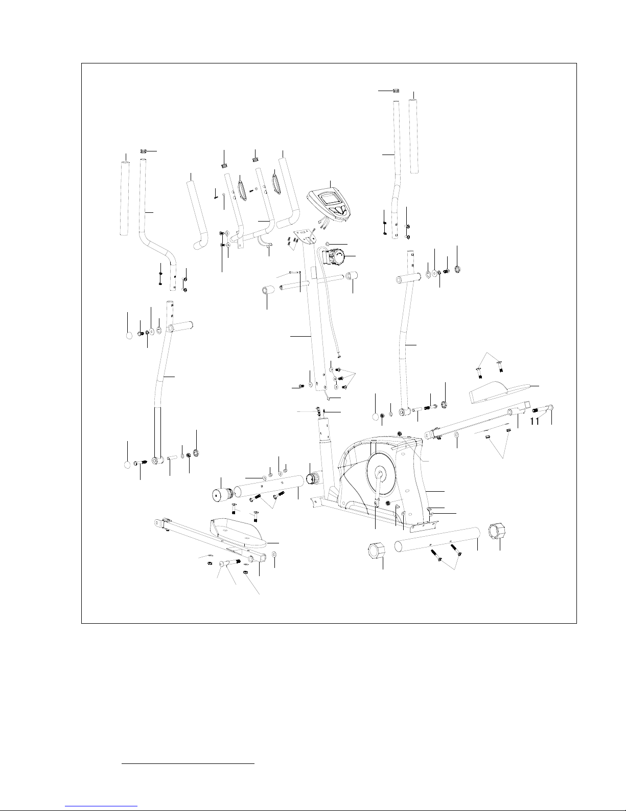
PART LIST
KEY NO. PART DESCRIPTION QTY
1 1700201 Main frame 1
2 1700202 Rear stabilizer 1
3 1700203 Front stabilizer 1
4 1700204 Leveling end cap 2
5 1700205 Transportation wheel 2
6 1700206 Carriage bolt M8*60 4
7 1700207 Curved washer Φ8*Φ20*1.5 10
8 1700208 Domed nut M8 4
9L 1700209L Pedal tube left 1
9R 1700209R Pedal tube right 1
10L 1700210L Hinge bolt left 1
10R 1700210R Hinge bolt right 1
11 1700211 Wave washer 2
12 1700212 Flat washer 2
13L 1700213L Pedal left 1
13R 1700213R Pedal right 1
14 1700214 Carriage bolt M10*45 4
15 1700215 PVC cap 6
16 1700216 Nylon lock nut M10 6
17 1700217 Washer Φ22*Φ10*1.5 6
18 1700218 Sleeve 2
19 1700219 Spring 1
20 1700220 Hex head bolt M10 x 65 2
21L 1700221L Bottom handlebar Left 1
21R 1700221R Bottom handlebar Right 1
22 1700222 Upright 1
23 1700223 Allen screw M8 x 16 6
24 1700224 Crank arm w/pulley 1
25 1700225 Tension control knob w/cable 1
26 1700226 Extension sensor wire 1
27 1700227 Lower Tension Cable 1
28 1700228 Sensor wire 1
29 1700229 Hex head bolt M10*20 2
30 1700230 Spring washer φ10 2
31 1700231 Flat washer Φ32*Φ10*1.5 2
32 1700232 D type washer 2
33 1700233 Hex head bolt M6*25 1
34 1700234 Plastic spacer 2
35 1700235 Allen screw M6 x 12 4
36 1700236 Carriage bolt M6*20 4

Customer Service 1-888-707-1880
11
PART LIST
KEY NO. PART DESCRIPTION QTY
37L 1700237L Top handlebar left 1
37R 1700237R Top handlebar right 1
38 1700238 Monitor 1
39 1700239
Stationary handlebar 1
40 1700240 End cap of handlebar 4
41 1700241 Hand pulse sensor 2
42 1700242 Self-tapping screw 2
43 1700243
Washer Φ6*Φ12*12
44 1700244 Foam grip for handlebar 2
45 1700245 Foam grip for top handlebar 2
46 1700246 Pulse wire 2
47 1700247 Grommet 1
48 1700248 Screw M5 x10 4
49 1700249 Flat washer 1
50 1700250 Bolt 1
51L 1700251L Nylon lock nut left 1
51R 1700251R Nylon lock nut Right 1
52L 1700252L Chain cover left 1
52R 1700252R Chain cover right 1
53 1700253 Crank cover 2
54 1700254 Self-tapping screw ST5 x 15 8
55 1700255 Self-tapping screw ST5 x 15 4
56 1700256 Flywheel 1
57 1700257 France nut 2
58 1700258 Adjustor set 2
59 1700259 Hex head bolt M6 2
60 1700260 Nylon nut M8 2
61 1700261 C-clip 2
62 1700262 Axle for flywheel 1
63 1700263 Hex head bolt M8*55 1
64 1700264 Bushing 2
65 1700265 Magnet assembly 1
66 1700266 Bearing assembly 1
67 1700267 Belt 1
68 1700268 Sensor bracket 1
69 1700269 Allen wrench S13,17 2
70 1700270 Allen key 6mm 1
71 1700271 Allen key 4mm 1
72 1700272 Allen key 8mm 1
Customer Service 1-888-707-1880
12
DIAGRAM
1
2
3
4
4
5
5
6
67
7
7
7
7
7
7
8
8
88
9L
9R
10L
10R
11
12
12
13R
13L
14
14
15
15
15
15
15
15
16
16
17
17
18
18
20
20
21L
21R
22
23
23
23
24
25
26
2827
29
29
30
31
32
31
32
30
34
34
35
35
36
36
37L
37R
38
39
4040
40
40
41
41
42
43
44
44
45
45
46 48
47
49
50
51L
51R
17
16
17
16

Customer Service 1-888-707-1880
13
24
28
27
27
28
52L
52R
53
53
54
54
55
55
55
54
1
56
57
57
58
58
61
61
62
63
64
64
60
65
66
66
67
68
19
33
59

Customer Service 1-888-707-1880
14
MONITOR INSTRUCTIONS
FUNCTION BUTTONS:
Mode: Press to select functions between: scan, time, speed, distance ,Odometer ,
calories and pulse
Set: Press to preset the target value of time, distance ,Calories and pulse.
Reset: Press to reset your preset value to zero.
Press and hold for 2 seconds to reset all values to zero except odometer.
FUNCTIONS:
Scan: Displays each function in sequence every 6 seconds. The display loop is Time-
Speed-Distance- Odometer -Calories-Pulse
Time: Shows your elapsed workout time up to 99:59
Counts down from your preset target time to 00:00 during your workout.
Speed: Displays the current speed up to 99.9 mile.
Distance: Displays the cumulative distance traveled during your workout up to 99.99m
Counts down from your preset target distance to 0.0 during your workout.
Calories: Displays the cumulative calories burned at any given time during your workout
up to 999 cal.
Counts down from your preset target calories to 0.0 during your workout.
Note: This is a rough guide used for comparison of different exercise sessions,
which cannot be used for medical purposes.
Odometer: Displays the total distance accumulated up to 9999 mile.
Pulse: Displays your pulse rate in beats per minute during your workout.
Counts down from your preset target pulse to 0.

Customer Service 1-888-707-1880
15
Monitor Function:
How to preset time, distance,calories and pulse.
Press the mode button until desired function is displayed.
Press the set until your desired number is displayed.
Press the mode button to accept value
The monitor will count down from your preset value once you start exercising.
The monitor will beep to indicate the completion of your preset value. Press any button to
stop the beep and the monitor will now start to count up.
If more than one value is preset, the first to reach the value will sound the alarm. Once you
have stopped the alarm the next preset value will sound the alarm until you have reached all
preset values.
Remarks
1. Monitor requires two “AA” batteries
2. The monitor will turn on automatically by pressing any key or when you start pedaling.
3. The monitor will turn off automatically if no signal is detected for four minutes.
4. To reset the odometer, you must remove the batteries.
5. If monitor is illegible or partial segments appear, remove batteries and wait 15 seconds
to re-install.
6. The batteries must be removed from the appliance before it is scrapped and that they are
disposed of safely.

Customer Service 1-888-707-1880
16
TROUBLE SHOOTING
Problem Cause Correction
Monitor does not display Batteries not installed Insert batteries
Sensor wire not connected
Securely plug sensor wire
into extension wire
and at the back of the
monitor
Sensor wire not working
properly Replace sensor wire
No speed or distance
displays on the monitor
Monitor not working properly Replace monitor
Tension control not connected
Securely connect the
tension control into the
extension tension control
wire
No tension
Magnetic wheel not working
properly Replace magnetic wheel
Pulse wire not connected Securely plug wires together
Hand pulse defective Replace hand pulse grip
Heart rate not displaying
Monitor not working properly Replace monitor
Crank bearing defective Replace crank bearings
Grinding noise
Mag wheel defective Replace magnetic wheel
Squealing V-belt slipping Adjust v-belt

Customer Service 1-888-707-1880
17
Getting on / off your elliptical
IMPORTANT
The elliptical comes with two Dual Action Handles and a Stationary Handlebar.
Always hold the Stationary Handlebar when getting on and off the elliptical.
First time users should familiarize themselves with using the elliptical by using the
Stationary Handlebar first and then progressing to the Dual Action Handles.
Once you have familiarized yourself with using the elliptical, you can progress to using the
Dual Action Handles to provide a total body workout. Hands can be positioned on the Dual
Action Handles at the most appropriate position for your height and arm length.
Caution should always be taken when getting on and off any exercise machine.
Please follow the safety steps below.
Ensure the left Foot Pedal is in the lowest position and grasp
the Stationary Handlebar with both hands.
Place your left foot on the left Foot Pedal and get secure.
Lift your right foot over machine and place on right Foot
Pedal. Get balanced and begin your workout.
Important
To get off, come to a complete stop and reverse the procedure.
Always wear rubber-soled shoes, such as tennis shoes.
It is recommended that you keep at least one hand on the Stationary Handlebar
at all times, especially when getting on or off. If you are performing a walking
action with your arms, or doing upper body strength training exercises, ensure
you are well balanced.
All equipment should be set-up and operated on solid, level surfaces.

Customer Service 1-888-707-1880
18
Correct Position
Your body should be in an upright position so that your back is
straight. Keep your head up to minimize neck and upper back
strain.
Always try and use the elliptical in a rhythmical and smooth
motion. If you find yourself feeling uncomfortable, or experience
a surging type feeling, there is probably too much tension.
The elliptical can be used in forward or reverse notion.
When going in reverse, bend your knees slightly more. More
emphasis is on the buttocks and hamstrings in the reverse
motion.
MOVING YOUR ELLIPTICAL
The elliptical can be easily moved from room to room.
1.Move to the front of the machine and ensure swing
arms are even (one foot pedal at top of Elliptical Chain
Cover and other at bottom).
2.Grasp both Dual Action Handles together and pulling
back on handles, tip machine towards you.

Customer Service 1-888-707-1880
19
HOW TO ADJUST THE RESISTANCE OF THE PEDALS
As you exercise, you can adjust the resistance of the pedals with the resistance knob
mounted on the upright. To increase the resistance, turn the knob clockwise; to decrease the
resistance, turn the knob counter-clockwise.
MAINTENANCE
To clean the elliptical, use a damp cloth and a small amount of mild soap.
IMPORTANT: To avoid damage to the console, keep liquids away from the console and
keep the console out of direct sunlight.
HOW TO ADJUST THE REED SWITCH
If the console does not display correct feedback, the reed switch should be adjusted. To
adjust the reed switch, the Chain Cover (52) must first be removed.
Remove the Carriage Bolt (14) , the Washer (17) and Nylon Lock Nut (16) from the Left
Pedal (13L). Remove the Left Hinge Bolt (10L), Wave washer (11), Flat Washer (12) and
Nylon Lock Nut (51L) from the rear of left Pedal Tube (9L). Repeat for the right side (not
shown) in the same way. Remove the two ST5 x 15 Self-tapping Screws (55) from each side
of the Chain Cover (52). Remove another seven ST5 x 15 Self-tapping Screws (54) from left
Chain Cover (52L). Remove the Crank Cover (53) from the Chain Cover (52). Hold the Chain
Cover (52) near the back and pull it apart slightly until the Chain Cover can be lifted off the
ends of the Crank (24).
Do not pull the Chain Cover apart at the top or the seam may be broken.
Next, locate the Sensor Wire (28). Turn the Pulley until the Magnet is aligned with the Reed
Switch. Loosen, but do not remove, the ST5 x 15 Screw (54). Slide the Reed Switch slightly
toward or away from the Magnet. Make sure that the Magnet will not hit the Reed Switch.
Retighten the Screw. Turn the Pulley for a moment. Repeat until the console displays correct
feedback.
When the Reed Switch is correctly adjusted, reattach the Chain Cover and the Crank Covers.
Table of contents


