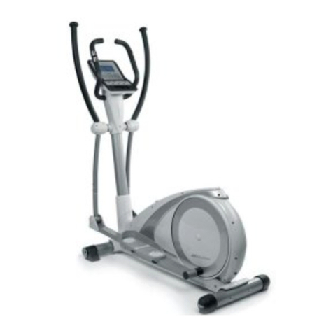
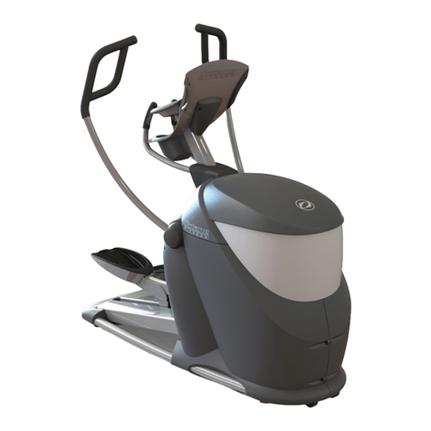
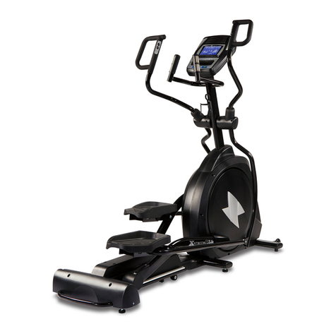
Xer Fit 770F User manual

USER’S MANUAL
for
770F Elliptical
BUILT FOR HEALTH

4*
M8*55L M8
1*
Assembly Step# 1
1) Attach the Front Stabilizer (D-1) to
the main base using Hex screw
(H-1).
2) Attach the Rear Stabilizer (E-1) to
the mid-frame extrusions of the
main base using Carriage screw
(H-2), Flat washers (H-3), and Nuts
(H-4) as shown above.

M8xP1.0x20L φ8xφ25x2t
Assembly Step # 2
1) Assemble the Left padel arm
(F-7) to the main frame with
Nylok screw (F-9), Flat washer
(F-10) and Cover for connector
bracket (F-28).
2) Assemble the Right padel arm
(F-8) to the main frame with
Nylok screw (F-9), Flat washer
(F-10) and Cover for connector
bracket (F-28).

Assembly Step # 3
1) Remove the preinstalled mounting hardware
from the main base.
2) Connect the Upper Cable wire (C-2) to the
Lower Cable Wire (G-2).
3) Slide the Handlebar post (C-1) down onto the
base assembly. Align the mounting holes and
thread the 3 in 1 bolt (C-3) in place as shown.
4) Insert the shaft (C-4) through the main pivot area
of the Handlebar post (C-1). Assemble each of
the Lower handlebars Right/ Left (I-3/I-4) onto
the shaft carefully following the hardware
orientation shown above.
|O M8*20L 10* 26 10* 25
2*
17.5* 25*0.3T 17.5* 25*0.3T
4* 2*
M8*20L
4* 1*

Assembly Step # 4
1) Assemble the right and left Pedal
(F-1/F-2) to the corresponding pivot
collars referencing the orientation
shown in the drawing. Hardware
used per side: Linkage arm (F-4),
Flat washer (F-5), Screw (F-6).
2) Align the screw mounting patterns of
left and right Foot Pedal (F-26/F-27)
with the corresponding pedal arm
plates. Secure each foot plate to the
pedal arm using Screw (H-21). Make
sure the orientation of the pedal
plates is correct.
3) Attach the Lower handlebars Right/
Left (I-3/I-4) to the linkage of the
pedal assemblies using Screw
(H-17), Bushing (H-18), Flat washer
(H-19) and Nut (H-20) per side.
Make sure to follow the orientation
shown in the drawing.
M8*P1.25*50L16*36.5L | O8*| O16*1T M8
M5*14L
2*
10*
3T M8*16L 8* 19*2T
2* 6*
1*

Assembly Step # 5
1) Attach both Upper handlebar (I-1/I-2) to the corresponding
Lower handlebars using Carriage screw (H-15), Curve washer
(H-16) and Nut (H-5) per side.
M8x40L 8* 19*2T M8
4* 1*

Assembly Step # 6
1) Carefully routes the Pulse cable coming through
the middle of the Handlebar post (C-1).
2) Secure the Front Handlebar (B-1) to the Handlebar
post (C-1) using a combination of Round Hex
screw (H-13), Spring screw (H-12) and Flat washer
(H-11). Once the U handle is secured to the mast,
place the Clamp cover (H-14) over the mounting
area.
? 7*1t ? 7*2t M7*P1.0*30L
1* 1*

Assembly Stage # 7
1) Connect the Pulse cable and Upper Cable wireinto the board mounted
connector on the back of the computer.
2) Tuck the excess cable length into the mounting bracket and attach the
computer to the mounting bracket using Screw (A-2).
3) Plug in the cord end of the Adaptor (G-26) into the receptacle located
on front of the base assembly / shroud.
M5*10
4* 1*

Assembly drawing

Assembly parts in the carton

Explored drawing

Part List
NO
Description
Q'ty
A
Computer Assembly
1
SET
A-1
Computer
1
PCS
A-2
Screw
4
PCS
B
Handlebar Assembly
1
SET
B-1
Front Handlebar
1
PCS
B-2
Hand pulse
2
PCS
B-3
end cap
2
PCS
B-4
Grip for handlebar
2
PCS
B-5
Pulse cable
1
PCS
B-6
Cap for wire
1
PCS
C
Handlebar Post Assembly
1
SET
C-1
Handlebar post
1
PCS
C-2
Upper Cable wire
1
PCS
C-3
3 in 1 bolt
4
PCS
C-4
shaft
1
PCS
C-5
Metal bushing
2
PCS
C-6
Screw
2
PCS
D
Front Stabilizer Assembly
1
SET
D-1
Front Stabilizer
1
PCS
D-2
end cap left
1
PCS
D-3
end cap right
1
PCS
D-4
Screw
2
PCS
D-5
Adjustment end cap
2
PCS
D-6
adjustment plate
2
PCS
E
Rear Stabilizer Assembly
1
SET
E-1
Rear Stabilizer
1
PCS
E-2
end cap
2
PCS
E-3
Screw
4
PCS
E-4
end cap
2
PCS
E-5
Adjustment end cap
4
PCS
E-6
adjustment plate
4
PCS
F-1
Pedal Left
1
PCS
F-2
Pedal Right
1
PCS
F-3
end cap
2
PCS
F-4
Linkage arm
2
PCS
F-5
Flat washer
6
PCS

NO
Description
Q'ty
F-6
Screw
6
PCS
F-7
Left padel arm
1
PCS
F-8
Right padel arm
1
PCS
F-9
Nylok screw
2
PCS
F-10
Flat washer
2
PCS
F-11
Shaft busing of handlebar
4
PCS
F-12
Connector bracket of pedal tube
2
PCS
F-13
Screw
2
PCS
F-14
Flat washer
4
PCS
F-15
Nut
2
PCS
F-16
Wave washer
2
PCS
F-17
Metal bushing
4
PCS
F-18
roller cap
2
PCS
F-19
screw
4
PCS
F-20
screw
4
PCS
F-21
Flat washer
4
PCS
F-22
Bearing
4
PCS
F-23
Fixed tube
2
PCS
F-24
roller wheel
2
PCS
F-25
Bushing of lower handlebar connector
4
PCS
F-26
Foot Pedal Left
1
PCS
F-27
Foot Pedal Right
1
PCS
F-28
Cover for connector bracket
2
PCS
G-1
Main frame
1
PCS
G-2
Lower Cable Wire
1
PCS
G-3
C-type ring
1
PCS
G-4
Wave washer
1
PCS
G-5
Flat washer
1
PCS
G-6
Bearing
2
PCS
G-7
Belt
1
PCS
G-8
Side case-Left
1
PCS
G-9
Side case-Right
1
PCS
G-10
Disc
2
PCS
G-11
Cap for Disc
2
PCS
G-12
Cross
2
SET
G-13
Flat washer
8
PCS
G-14
self-tapping screw
8
PCS

NO
Description
Q'ty
G-15
Texture nut
2
PCS
G-16
self-tapping screw
7
PCS
G-17
screw
8
PCS
G-18
Connecter for roller arm
1
PCS
G-19
Sensor box
1
PCS
G-20
Screw
1
PCS
G-21
Alex
1
PCS
G-22
Screw
3
PCS
G-23
Pulley
1
PCS
G-24
Bushing
1
PCS
G-25
DC wire
1
PCS
G-26
Adaptor
1
PCS
H
Screw Kit
1
SET
H-1
Screw
2
PCS
H-2
Carriage screw
2
PCS
H-3
Flat washer
2
PCS
H-4
Nut
6
PCS
H-5
Curve bushing
2
PCS
H-6
Nylok screw
2
PCS
H-7
Flat washer
2
PCS
H-8
Plastic washer
2
PCS
H-9
Flat washer
4
PCS
H-10
Wave washer
2
PCS
H-11
Flat washer
1
PCS
H-12
Spring screw
1
PCS
H-13
Round Hex screw
1
PCS
H-14
Clamp cover
1
PCS
H-15
Carriage screw
4
PCS
H-16
Curve washer
4
PCS
H-17
Screw
2
PCS
H-18
Bushing
2
PCS
H-19
Flat washer
2
PCS
H-20
Nut
2
PCS
H-21
Screw
10
PCS
I
Moveable handlebar assembly
1
SET
I-1
Upper handlebar left
1
PCS
I-2
Upper handlebar right
1
PCS

NO
Description
Q'ty
I-3
Lower handlebar left
1
PCS
I-4
Lower handlebar right
1
PCS
I-5
Foam grip
2
PCS
I-6
End cap
2
PCS
I-7
Metal bushing
4
PCS
J
Magnetic Assembly
1
SET
J-1
Magnetic
1
PCS
J-2
Screw
1
PCS
J-3
Spring screw
2
PCS
J-4
Screw
2
PCS
J-5
Flat washer
2
PCS
J-6
Bushing'
1
PCS
J-7
Nut
1
PCS
J-8
Flat washer
1
PCS
J-9
Gear box
1
PCS
K
Flywheel Assembly
1
SET
K-1
Flywheel
1
PCS
K-2
Texture nut
2
PCS
K-3
Nut
3
PCS
K-4
Bushing
1
PCS
K-5
Bearing
1
PCS
K-6
Flywheel axle
1
PCS
K-7
Bearing
1
PCS
K-8
Flat washer
1
PCS
L
Idler Assembly
1
SET
L-1
Idler
1
PCS
L-2
Screw
1
PCS
L-3
Nut
1
PCS
L-4
Flat washer
1
PCS
L-5
Spring
1
PCS
L-6
Screw
1
PCS
L-7
Flat washer
1
PCS
L-8
Screw
1
PCS
L-9
Idler wheel
1
PCS

INSTRUCTION MANUAL OF
SM2749-67
BUTTON FUNCTION:
MODE
In stop mode, the mode is to confirm all exercise data setting, and enter into program.
RESET
In stop mode, press the button back to main menu.
START/STOP
To start or stop exercise.
RECOVERY
To test heart rate recovery status.
UP
To select training mode and adjust function value up.
DOWN
To select training mode and adjust function value down.
DISPLAY EXERCISE DATA:
TIME
Display range 0:00~99:99 ; Setting range 0:00~99:00
DISTANCE
Display range 0.00~99.99 ; Setting range 0.00~99.90km
CALORIES
Display range 0~9999 ; Setting range 0.00~9990
PULSE
Display range P-30~240 ; Setting range 0-30~240
WATT
Display range 0~999 ; Setting range 10~350
SPEED
0~99.9km
RPM
0~999
OPERATION PROCEDURE
1. Connect power supply and computer will power on with a long beep sound, LCD display all segments for 2
seconds.
In main menu, first exercise program MANUAL will flash, user may press UP and DOWN button to
select MANUAL PROGRAM USER PROGRAMHRCWATT.
2. Quick Start and Manual :
Before exercise in Manual mode, user my set up TIME, DISTANCE, CALORIES and PULSE target.
After power on, user may press START/STOP button to start exercise in MANUAL immediately without any
setting.
Level can be adjusted during exercise by press UP or DOWN.
3. PROGRAM:
Before exercise in Program mode, user may set up TIME target.
Press UP and DOWN to select Program with 12 profiles and press ENTER/MODE to confirm.
Level can be adjusted during exercise by press UP or DOWN.
4. H.R.C.:
To exercise in H.R.C. mode, user may select pulse target for 55%, 75%, 90% or TARGET pulse. And set up
TIME target to start workout.
5. USER PROGRAM:
User may press UP, DOWN and then press MODE to create his own profile. (from column 1 to column 20)
User may hold on pressing MODE button for 2 seconds to quit profile setting.
6. WATT :
The preset watt value 120 is flashing on screen in WATT setting mode. User may use UP, DOWN button
to set target value from 10 to 350 and set up TIME target. Press MODE button for confirm.
9. RECOVERY :
After exercising for a period of time, keep holding on handgrips and press “RECOVERY”
button. All function display will stop except “TIME” starts counting down from 00:60 to 00:00.
Screen will display your heart rate recovery status with the F1,F2….to F6. F1 is the best, F6
F6 is the worst. User may keep exercising to improve the heart rate recovery status.
(Press the RECOVERY button again to return the main display.)

NOTE:
1. This computer require 9V, 0.5mA adaptor.
2. When user stop pedaling for 4 minutes, computer will enter into power save mode, all setting and exercise
data will stored until user start exercise again.
3. When computer act abnormal, please plug out the adaptor and plug in again.

IMPORTANT INFORMATION REGARDING SERVICE
In you have any problems, please contact Mylna Service. Our consultants have extensive experience and will
help you with questions about products, installation, ordering spare parts or any errors and omissions.
We would like you to contact us before contacting the store so we can offer you the best help.
Please visit our website www.xerfit.fi - here you will find information about the products and user manuals in
Finnish and English. On our website you can find a contact form and this gives us the information we need to
assist you as efficiently as possible.
Table of contents
Other Xer Fit Elliptical Trainer manuals