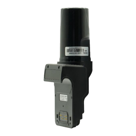
Sirona SICAT JMT+ User manual

Instructions for use – English
SICAT JMT JAW MOTION ANALYSIS SYSTEM
+

Contents
Page 2 of 37 SICAT JMT⁺ Jaw Motion Analysis System
Contents
1User information..................................................................................................................................... 4
1.1 Manufacturer information.......................................................................................................................................... 4
1.2 Configuration of the operating instructions ............................................................................................................. 4
1.3 Used symbols.............................................................................................................................................................. 4
2Area of use and safety ............................................................................................................................. 6
2.1 Intended use ............................................................................................................................................................... 6
2.1.1 Use .................................................................................................................................................................. 6
2.1.2 SICAT data export .......................................................................................................................................... 7
2.2 Safety .......................................................................................................................................................................... 7
2.2.1 Environmental conditions ............................................................................................................................. 7
2.2.2 Storage and transport ................................................................................................................................... 7
2.2.3 Obligations of the user................................................................................................................................... 8
2.2.4 General safety information............................................................................................................................ 8
2.2.5 Safety information on heart pacemakers / defibrillators ............................................................................ 9
2.2.6 Prohibited use .............................................................................................................................................. 10
3Product description............................................................................................................................... 11
3.1 System components................................................................................................................................................. 11
3.2 Technical data of the SICAT JMT⁺ measurement system ...................................................................................... 11
3.3 Measurement principle of the SICAT JMT⁺ jaw motion analysis system .............................................................. 11
3.4 Control elements and connections ......................................................................................................................... 12
3.5 Meaning of the display lights ................................................................................................................................... 14
3.6 Assignment of the connecting sockets.................................................................................................................... 15
3.7 Accessories and spare parts..................................................................................................................................... 16
4Putting the measurement system into operation ..................................................................................... 20
4.1 Power supply and charging the battery .................................................................................................................. 20
4.2 Computer requirements........................................................................................................................................... 20
4.3 Installing the SICAT JMT⁺ software......................................................................................................................... 21
4.4 Connecting the accessory parts............................................................................................................................... 21
4.5 Taking the measurement system out of operation ................................................................................................ 22
5Functional checks, preparation, disposal ................................................................................................ 23
5.1 Specified regular checks and technical safety checks ........................................................................................... 23
5.2 Checking the measurement function...................................................................................................................... 24
5.3 Rectifying faults ........................................................................................................................................................ 24
5.4 Preparation methods ............................................................................................................................................... 25
5.4.1 Manual cleaning........................................................................................................................................... 25
5.4.2 Manual disinfection...................................................................................................................................... 26
5.4.3 Sterilization .................................................................................................................................................. 26
5.5 Disposal..................................................................................................................................................................... 26
5.5.1 Packaging ..................................................................................................................................................... 26
5.5.2 Disposal of electronic waste........................................................................................................................ 27
5.5.3 Accumulators and batteries ........................................................................................................................ 27
6Safety standards and classification of the system .................................................................................... 28

Contents
SICAT JMT⁺ Jaw Motion Analysis System Page 3 of 37
6.1 Classification pursuant to appendix IX of the Directive 93/42/EEC ....................................................................... 28
6.2 Safety of electrical medical devices ........................................................................................................................ 28
6.2.1 Connection of the SICAT JMT⁺ measurement system with other electrical devices ............................... 28
6.2.2 Environment of the patient / test person ................................................................................................... 29
6.3 Electromagnetic compatibility for guidelines / manufacturer declaration .......................................................... 29
Glossary ............................................................................................................................................... 34
Index.................................................................................................................................................... 35
7Contact ................................................................................................................................................ 36

USER INFORMATION
Page 4 of 37 SICAT JMT⁺ Jaw Motion Analysis System
USER INFORMATION
MANUFACTURER INFORMATION
SICAT GmbH & Co. KG
Brunnenallee 6
53177 Bonn
Germany
Telephone +49 (0)228 / 854697-11
Email: [email protected]
Internet: www.sicat.com
CONFIGURATION OF THE OPERATING INSTRUCTIONS
The operating instructions for the SICAT JMT⁺ jaw motion analysis system consist of two parts:
1. SICAT JMT+ system technical data and instructions for use
2. SICAT JMT+ instructions for use of the user software
The part SICAT JMT+ system technical data and operating Instructions primarily contains information
concerning the technical data and operation of the SICAT JMT+ system, as well as information on its safe
operation in combination with the patient accessories such as the bite-fork or infrared remote control.
Information concerning accessory components is limited to key safety and maintenance measures
and/or hygiene measures.
CAUTION
The exact compliance with the information in both parts of the operating
instructions is required for proper use.
USED SYMBOLS
Green highlighting around the side of the instructions for use designates new information concerning
product safety.
Warning instructions designate a potential danger to the health and safety of users and/or patients. The
instructions explain the type of danger and how it can be avoided.
NOTICE Notices designate a potential danger that can cause damage to the device. The
instructions explain the type of danger and how it can be avoided.
The CE mark with code number 0197 of the notified body TÜV Rheinland LGA Products GmbH confirms
the conformity of the measurement system with guideline 93/42/EEC (Medical Devices Directive).
1
1.1
1.2
1.3

USER INFORMATION
SICAT JMT⁺ Jaw Motion Analysis System Page 5 of 37
Symbol for manufacturer and date of manufacture
Type BF device corresponding to DIN EN 60601-1
USB connection
This symbol shows that pursuant to the Directive on Waste Electrical and Electronic Devices (2012/19/EU)
and national legislation, a product cannot be disposed of via the household waste, and must be disposed
of separately within Europe.
Symbol for RF transmitters (Bluetooth interface)
Article number of the measurement system / accessory
Serial number of the measurement system
An accessory that is intended for one-off use on a single patient during a single treatment.
Read the instructions for use, especially the safety information.

AREA OF USE AND SAFETY
Page 6 of 37 SICAT JMT⁺ Jaw Motion Analysis System
AREA OF USE AND SAFETY
INTENDED USE
Based on the lower jaw movements of the patient, the SICAT JMT+ system calculates all the necessary
parameters with the goal of a supporting diagnosis for the following indications:
■ supporting diagnosis for treating a diseased mandibular joint
■ supporting diagnosis for creating occlusal mouth-guards
■ supporting diagnosis for creating dentures
■ supporting diagnosis for aesthetically functional reconstruction with or without tooth implants
■ supporting diagnosis for treating craniomandibular dysfunction (CMD)
The measurement system also enables the exporting of the gathered data for further processing with
CAD/CAM or PACS systems.
The measurement system may only be used by trained dentists. The area of use is limited to dental
systems. A measurement is carried out within 15 minutes and should not be applied in the case of open
wounds in the oral and head area; it can be applied to patients who are over 10 years old and who are
mentally capable of exactly following the instructions of the operator.
USE
The SICAT JMT+ system is an electronic recording system that is based on 3D ultrasound measurements.
SICAT JMT+ systems record the lower jaw movements of the patient in all degrees of freedom.
The 3D presentation of the positions and movement paths of occlusal or juxta-articular measurement
points provides important information on the movement behavior of the mandibular joint and the teeth
on the lower and/or upper jaw. The 3D presentation of distinctive positions in the face provides a
mapping of the facial symmetry for the fitting of the denture. In a functional, preliminary examination,
any discoordinations and limitations of movement can be analyzed and documented.
The electronic position analysis of the condyles enables different occlusion positions to be compared and
can thereby indicate possible pain vectors in the joint.
An analysis of the chewing movements takes place with a special software module. The XML export
function enables the use of jaw movements determined with the SICAT JMT+ system in CAD/CAM systems
and PACS systems for the functional optimization of dentures and of mouth-guards.
The measurement system may only be used by trained personnel, meaning dentists in dental facilities.
The SICAT JMT+ is used to support the functional diagnosis. The measurement sensor technology consists
of a receiving sensor and a transmitting sensor. This is attached to the patient's head. The lower jaw
sensor technology is fitted with a special locking mechanism for fixing it to the attachment. The face bow
is positioned at the front with the support on the nasion and at the back of the head above the ears. A
measurement can then be carried out according to the required settings and measurement parameters
in the software.
All the measurement and/or analysis results of the SICAT JMT+ system should always be interpreted by a
trained specialist and checked for their relevance in consideration of the clinical medical history of the
patient and in the context of the further diagnostic procedure. If invasive measures are taken, the
measurement system should only be used as an additional assessment method. Under no circumstances
can or should invasive surgery or measures that put the patient at risk be carried out based on the
measurement results alone.
2
2.1
2.1.1

AREA OF USE AND SAFETY
SICAT JMT⁺ Jaw Motion Analysis System Page 7 of 37
SICAT DATA EXPORT
The XML export function enables the use of jaw movements determined with the SICAT JMT+ system in
CAD/CAM systems and PACS systems for the functional optimization of dentures and of mouth-guards. A
connecting cup serves as an interface for the referencing. It carries reference marks that can be captured
by imaging systems such as surface scanners or DVT.
SAFETY
ENVIRONMENTAL CONDITIONS
The SICAT JMT+ jaw motion analysis system is suitable for use in dry interior rooms, as can be found in
clinics, medical practices and laboratories.
Permissible operating temperature: 10°C to 40°C
Relative humidity: 30 % to 70 %
CAUTION
The device should not be operated in wet zones, damp areas (swimming baths,
saunas) or climatic chambers.
The measurement systems are not intended for use in areas where there is a risk
of explosion, rooms used for medical purposes or in a flammable atmosphere
(oxygen-enriched).
The devices should not be used near engines or transformers with a big
connected load, for example, or heavy current power lines, as electrical or
magnetic interference fields can distort the correct measurements and/or make
them impossible.
To avoid reciprocal faults from occurring, two SICAT JMT+ systems should never
be operated in the same room or near other ultrasound emitting devices (e.g.
ultrasonic cleaners, bird scare devices, alarm systems), as this can cause the
measured values to be falsified.
STORAGE AND TRANSPORT
The storage and transport of the measurement system should only be carried out in the original
packaging, as provided by SICAT.
Storage temperature: -20°C to +70°C
Relative humidity: 5% to 90%
Air pressure: 700 hPa to 1060 hPa
2.1.2
2.2
2.2.1
2.2.2

AREA OF USE AND SAFETY
Page 8 of 37 SICAT JMT⁺ Jaw Motion Analysis System
OBLIGATIONS OF THE USER
■ The general guidelines and/or national legislation, national regulations and technical regulations
pertaining to medical products are to be applied and fulfilled both with the start-up and during the
operation of the SICAT product appropriate to the stated purpose. In Germany, operators, those
responsible for such devices, and users are obliged to operate their devices in compliance with the
MPG (Medical Devices Act) regulations.
■ It is the obligation of the user:
– to comply with all the safety instructions stated in the operating instructions.
– to carry out all of the inspection and maintenance work regularly as specified in the operating
instructions.
– to only use fault free working equipment.
– to ensure that the device is functionally safe and in a proper state prior to every instance of use of
the device.
– to ensure all the provided operating instructions that form part of the measurement system, are
accessible to all users at all time, and to keep them near the measurement system.
– to protect oneself, the patients and third parties against dangers.
– to prevent a contamination occurring due to the product.
■ During use, it is necessary to comply with the legal regulations, especially:
– the current work safety regulations.
– the current accident prevention measures.
■ Responsibility is assumed to ensure the safety, reliability and effective performance of all
measurement systems and accessories delivered by SICAT, such that:
– assembly work, extensions, new settings, changes or repairs are carried out by SICAT or third
parties authorized by SICAT, trained technicians or by the personnel of authorized dealers. The
storage and transport should only be carried out in the original packaging, as provided by the
manufacturer.
– the product is operated in compliance with the operating instructions.
– the information technology components provided by the operator comply with the technical
requirements for hardware and software contained in these operating instructions, and that they
are installed and set up according to the applicable descriptions for these components.
– the place of installation corresponds with the specified environmental conditions for the
measurement system and the current installation regulations.
– only the software made available by SICAT, as well as the components and accessory parts listed
in these operating instructions are used with the system.
GENERAL SAFETY INFORMATION
■ The use and operation of the system and the evaluation of measurement data and its interpretation
should only be carried out by trained specialist personnel. The manufacturer assumes no liability for
damage to persons or property, or the loss of data that may occur due to the improper use of the
software, the device, or its accessory parts.
■ Patients and measurement data may only be copied, moved or deleted with the help of the database
function that is provided by the SICAT applications programs. In the case of the deliberate changing
of data without the database functions, the user alone bears the full risk.
■ All measurement and/or analysis results should always be interpreted by a trained specialist and
checked for their relevance in consideration of the clinical medical history of the patient and in the
context of the further diagnostic procedure. If invasive measures are taken, the measurement system
2.2.3
2.2.4

AREA OF USE AND SAFETY
SICAT JMT⁺ Jaw Motion Analysis System Page 9 of 37
should only be used as an additional assessment method. Under no circumstances can or should
invasive surgery or measures that put the patient at risk be carried out based on the measurement
results alone.
■ In the case of malfunctions and/or defects being suspected and/or ascertained, the device has to be
taken out of use immediately, labelled as 'Out of Use', and secured to prevent use. Please contact the
manufacturer or your sales partner immediately under all circumstances.
■ The measurement system has to be checked to ensure the measurement function is operating
correctly at regular intervals. For further information about this, please see the 'Functional checks
and preparation' chapter in this handbook.
■ Do not install the jaw motion analysis system near a source of heat or in direct sunlight behind a
window, as excessive heating can lead to incorrect measurement results.
■ Ensure that all power and connection cables are routed and protected so that nobody is able to trip
over them. Check all cables and connection plugs regularly for damage. Damaged power supply
units, plug connectors and cables must be replaced before further use.
■ The measurement system is not protected against the penetration of fluids. If fluid penetrates the
measurement system, switch it off and please contact the SICAT GmbH & Co. KG technical service
team.
■ Never introduce objects into components of the measurement system.
■ Before starting every measurement, it is necessary to ensure the correct choice and correct position
of the transmitters or application aids. The cables or the application aids (e.g. feeler) can present a
risk of injury to the patient. In this context, please consult the special instructions in the handbooks
of the application software, and do not allow children or mentally impaired patients to enter the
proximity of the device without supervision.
SAFETY INFORMATION ON HEART PACEMAKERS / DEFIBRILLATORS
■ In the magnetic coupling for the attachment of the lower jaw (LJ) sensor on the T-attachment there
are strong permanent magnets, such as those that are used on headphones on MP3 players. Under
especially unfavorable circumstances, at short distances (< 15 cm), these magnets can have a
negative impact on the functionality of certain implanted heart pacemakers and defibrillators.
Therefore, the LJ-sensor should not be positioned on the upper body of the patient on patients with
electronic implants.
■ Version BT devices contain a Bluetooth transmitter as an interface to the PC. Although there is so far
no evidence of a possible interference of heart pacemakers/defibrillators by Bluetooth transmitters,
the SICAT JMT+ system is not recommended to be used on patients with electronic implants using
the neck strap, but with the maintaining of a safety distance of at least 15 cm from the patient's
thorax.
■ No interference of electronic implants is to be expected from the ultrasonic transmitters used in the
measurement system, as the SICAT JMT+ system works with airborne sound and a very low sound
power of a few milliwatts. Due to the adverse connection during the transition from the air into the
human body, the noise intensity of the measurement signals is weakened strongly such that any
interference with implants, as well as any damage to tissue, is excluded.
2.2.5

AREA OF USE AND SAFETY
Page 10 of 37 SICAT JMT⁺ Jaw Motion Analysis System
PROHIBITED USE
■ Improper and/or prohibited use of the measurement system is not permitted and express warning is
herewith provided of such.
■ Do not under any circumstances attempt to maintain or prepare the measurement system in any way
other than as described in the operating instructions. This could cause the high sensitivity sensor
technology to be in impaired terms of its measurement accuracy.
■ In the case of malfunctions and/or defects being suspected and/or ascertained, the device has to be
taken out of use immediately, labelled as 'Out of Use', and secured to prevent use, with the on/off
switch being covered and secured with adhesive tape.
■ Changing or modifying the measurement system or its accessory parts without the written
permission of SICAT is not allowed. If the device is changed without permission, the operator is
obliged to carry out suitable examinations and inspections in order to guarantee the secure use.
■ SICAT measurement systems must not be operated in environmental conditions other than those
stated in the 'technical data' chapter (e.g. in an oxygen enriched environment, wet zones, damp
rooms, climactic chambers, low pressure-, high pressure-, or altitude chambers, etc.).
2.2.6

PRODUCT DESCRIPTION
SICAT JMT⁺ Jaw Motion Analysis System Page 11 of 37
PRODUCT DESCRIPTION
SYSTEM COMPONENTS
In the basic configuration, the SICAT JMT+ system consists of the following components:
■ JMT+ system basic unit
■ Lower jaw sensor (transmitter)
■ Head bow (receiver)
■ USB charger for supplying the measurement system for BT devices
■ USB cable adapter (type A for Mini-B, 3 m in length)
■ SICAT JMT+ application software
TECHNICAL DATA OF THE SICAT JMT⁺ MEASUREMENT
SYSTEM
VERSION SICAT JMT⁺ BT
Dimensions (W x H x D) 111 x 86 x 31 mm
Weight 205 g
Power supply 5V DC / 1W (USB to charge battery)
Battery yes
Measurement range 10 - 100 mm
Ultrasonic frequency 40 kHz
Max. measurement rate 50 Hz
Positioning accuracy in the occlusal area ± 0.1 mm (y); ± 0.2 mm (x,z) / ROM = 15 mm
Calculation accuracy articulator setting values ± 2.0°
USB interface USB mini
Bluetooth yes
MEASUREMENT PRINCIPLE OF THE SICAT JMT⁺ JAW
MOTION ANALYSIS SYSTEM
The jaw motion analysis system consists of the lower jaw sensor and the ultrasonic receiver module on
the head bow. The sensor technology components of the receiver and transmitter modules are each
attached in geometrically defined positions. The marking points consist of small, sequentially operated
3
3.1
3.2
3.3

PRODUCT DESCRIPTION
Page 12 of 37 SICAT JMT⁺ Jaw Motion Analysis System
ultrasonic transmitters. The accompanying head bow consists of six and/or eight ultrasonic
microphones. Both modules are connected with the evaluation electronics in the SICAT JMT+
measurement system via a connecting cable.
During operation, the ultrasonic transmitters continuously emit impulses, from the operating time of
which, between the transmitter and receiver microphones, the evaluation electronic calculates the
absolute room coordinates of the markers using a triangulation method.
The calculation of the measurement coordinates and further measurement parameters, as well as the
compensation of the disturbance variables, occurs on a PC-supported basis in the evaluation programs.
BLOCK DIAGRAM OF THE MEASUREMENT SYSTEM
CONTROL ELEMENTS AND CONNECTIONS
VIEW FROM FRONT
1
2
Head bow
LJ-sensor
3.4

PRODUCT DESCRIPTION
SICAT JMT⁺ Jaw Motion Analysis System Page 13 of 37
VIEW FROM SIDE
1
On/off switch
VIEW FROM ABOVE
1
2
3
4
5
Bluetooth (blue)
Operating display (green)
Measurement (orange)
Power supply/battery (yellow)
IR-sync
VIEW FROM BELOW
1
2
Bracket for neck strap
Name plate

PRODUCT DESCRIPTION
Page 14 of 37 SICAT JMT⁺ Jaw Motion Analysis System
MEANING OF THE DISPLAY LIGHTS
LED ON/OFF SWITCH MEANING
Green / operational status indicator
off 0 (off) The measurement system is
NOT in operation
lit up I (on) The measurement system is in
operation
Orange / measurement
off I (on) The measurement system is
initializing and ready for
measurement.
flashes I (on) The measurement system is
waiting for initialization,
measurement not possible yet.
lit up I (on) The measurement has started /
ultrasonic transmitters are
active.
Yellow / battery charging status
off I (on) USB cable and/or charger
connected, reduced charging as
soon as charging status > 95%
flashes 0 (off) USB cable and/or charger
connected, battery charging,
charging status < 95%
I (on) Battery level critical < 20%
Connect the USB cable or
charger immediately, as it is
possible that data will be lost if
the measurement is continued.
lit up 0 (off) USB cable and/or charger
connected, battery fully
charged, charging status 100%
Blue / Bluetooth connection
off I (on) The measurement system
initializes and is ready for
measurement.
3.5

PRODUCT DESCRIPTION
SICAT JMT⁺ Jaw Motion Analysis System Page 15 of 37
LED ON/OFF SWITCH MEANING
lit up I (on) The measurement has started /
the measurement system is
connected with the PC via
Bluetooth
ASSIGNMENT OF THE CONNECTING SOCKETS
LJ SENSOR / DIGITAL INPUT (LIGHT GREEN)
SIGNAL PIN
Marker 1 Pin 1
Marker 2 Pin 2
Marker 3 Pin 3
Marker 4 Pin 4
SSWBus Pin 5
n.c. Pin 6
SDA (I²C) Pin 7
Signal Pin
SCL (I²C) Pin 8
+3.3 Volt Pin 9
DRY_A Pin 10
DRY_G Pin 11
Dig. Input Pin 12
GND Pin 13
GND Pin 14
3.6

PRODUCT DESCRIPTION
Page 16 of 37 SICAT JMT⁺ Jaw Motion Analysis System
HEAD BOW /DIGITAL INPUT (WHITE)
SIGNAL PIN
Microphone 1 Pin 1
Microphone 2 Pin 2
Microphone 3 Pin 3
Microphone 4 Pin 4
SSWBus Pin 5
Mic-select Pin 6
SDA (I²C) Pin 7
SCL (I²C) Pin 8
+3.6 - 12 Volt Pin 9
DRY_A Pin 10
DRY_G Pin 11
Dig. Input Pin 12
GND Pin 13
GND Pin 14
ACCESSORIES AND SPARE PARTS
DESIGNATION FIGURE
SICAT JMT⁺ measurement system
for battery operation with Bluetooth interface
Head bow type 13R
for SICAT JMT+ measurement systems
Complete with nose pads, rear head band and top headband
3.7

PRODUCT DESCRIPTION
SICAT JMT⁺ Jaw Motion Analysis System Page 17 of 37
DESIGNATION FIGURE
Nose pads
suitable for all head bows
Support plate
suitable for all head bows
Support pad white
suitable for support plates
Packaging unit 5 pieces
Nose pad white
Packaging unit 5 pieces
Rear headband white
Packaging unit 5 pieces
Top headband white
Neck strap
LJ sensor type 24T
for SICAT JMT+ measurement systems
Indicator pointer 80
Medical steel, sterilizable
Length 80mm, ball diameter 1.5mm

PRODUCT DESCRIPTION
Page 18 of 37 SICAT JMT⁺ Jaw Motion Analysis System
DESIGNATION FIGURE
Para-occlusal attachment 90
for attachment to the front teeth
L = 60 mm / W = 90 mm, medical steel, sterilizable
Occlusal adapter
for attachment of the LJ-sensor to the occlusal attachment
Medical steel, sterilizable, length = 60mm
Occlusal attachment
made from LEXAN, suitable for gas and steam sterilization
Hint: single use item, not intended for multiple use
Bite fork type SI
made from LEXAN, suitable for gas and steam sterilization
Hint: single use item, not intended for multiple use
Bite fork adapter
for attachment of the LJ-sensor to the bite fork
IR remote control
for all SICAT JMT+ measurement systems
USB power supply unit with country adapter
for charging the SICAT JMT+

PRODUCT DESCRIPTION
SICAT JMT⁺ Jaw Motion Analysis System Page 19 of 37
DESIGNATION FIGURE
EU - Adapter USB power supply unit
UK - Adapter USB power supply unit
USA - Adapter USB power supply unit
Australia - Adapter USB power supply
World - Adapter USB power supply
USB adapter for SICAT JMT⁺
Data connection of measurement system and PC

PUTTING THE MEASUREMENT SYSTEM INTO OPERATION
Page 20 of 37 SICAT JMT⁺ Jaw Motion Analysis System
PUTTING THE MEASUREMENT SYSTEM INTO
OPERATION
For the commissioning of the jaw motion analysis system, a USB cable of type A to Mini-B, as well as the
installation CD are required with the SICAT JMT+ application software. All components are included in the
scope of delivery for the SICAT JMT+ system.
POWER SUPPLY AND CHARGING THE BATTERY
For the rapid charging of the battery of the SICAT JMT+ measurement system when it is in the deactivated
state, connect the charger with an AC outlet and a USB cable of type A to Mini-B with the Mini-USB socket
on the measurement system.
Alternatively, the measurement system can also be charged or operated directly on the USB socket of a
PC. To do this, connect the PC directly using a USB cable (type A to B or type A to Mini-B).
CAUTION
Only connect the USB charger that is approved and supplied by SICAT, and
arrange the measurement system such that the plug for the power socket is
easily accessible at all times and the device can be easily disconnected from the
mains.
NOTICE
Before connecting the charger to the mains, consult the name plate information
on the power supply unit, checking that the voltage and frequency is consistent
with the local data. Only connect if such consistency is given.
CAUTION
Carry out a full visual inspection to the power supply unit, power cable and plug,
as well as the protective contacts before the connection and/or operation of the
measurement system. Damaged power supply units, cables or plug connectors
must be replaced immediately by an authorized person.
COMPUTER REQUIREMENTS
For the requirements of the SICAT JMT+ system with concern to a PC/laptop, please refer to the operating
instructions on SICAT JMT+ software.
4
4.1
4.2
This manual suits for next models
1
Table of contents
Popular Measuring Instrument manuals by other brands
Extech Instruments
Extech Instruments FHT200 user guide

Mitutoyo
Mitutoyo ID-SX2 user manual
pico Technology
pico Technology TA061 user guide
Milwaukee
Milwaukee CALIBRATION 2238-20 Repair service instructions
Sierra
Sierra BioTrak 645i instruction manual
Bosch
Bosch GRL Professional 250 HV Original instructions
Emerson
Emerson Micro Motion 1700 Configuration and Use Manual
Fortinet
Fortinet FortiAnalyzer 1000B quick start guide

Endress+Hauser
Endress+Hauser Proline Promass I 300 PROFIBUS PA operating instructions

Bushnell GOLF
Bushnell GOLF Tour V5 Shift owner's guide
PASCO
PASCO PS-3521 instruction sheet

Kanomax
Kanomax Anemomaster 6036 user manual
