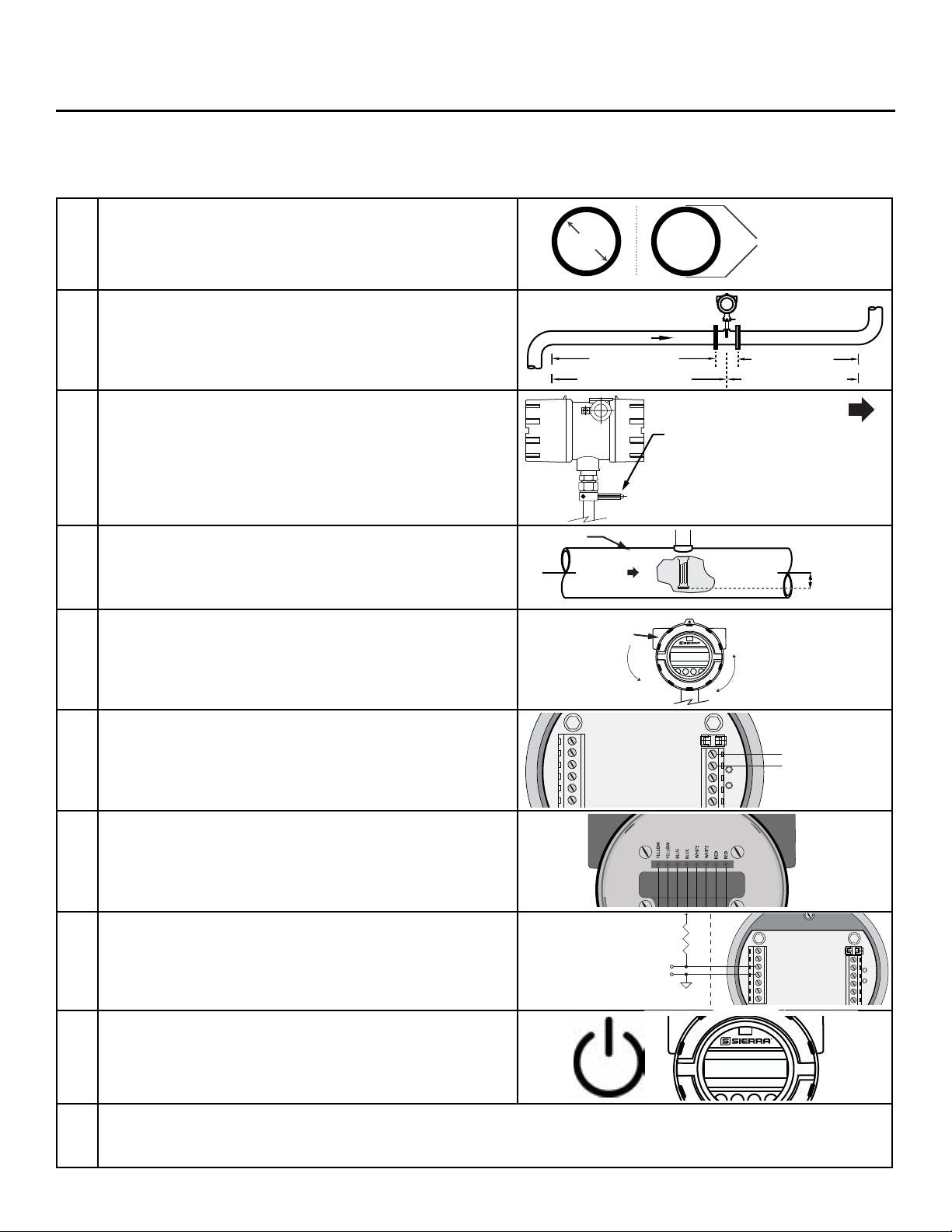
1. Record inside diameter (ID). Ensure the actual pipe ID
matches the pipe ID shown on the factory calibration
2.
Record up/downstream straight-pipe requirements
based on Pipe ID and meter style (insertion or inline).
[refer to p. 23]
3. The Flow Direction Indicator must point in the
The housing can be rotated for a better view of the
meter's display. Note that the 2 set screws must be
loosened before the housing will turn. [refer to p.
29]
4.
pipe, please see note on p. 26.
5.
If needed, the orientation of display can be rotated in
90° increments for a better view.
[refer to p. 30 for more information]
6.
Ensure power wiring [p. 37] and 4-20mA wiring [p.
39 - p. 40] properly connected. [refer to Wiring
section p. 35 for more information]
7.
Ensure remote wiring is correct if remote option
ordered.
[refer to p. 46 - p. 48 for more information]
8.
Verify you have the proper output signal wiring
[refer to p. 39 - p. 45 for more information]
9.
10.
of the display or by using the BioViewTM Software. Record the settings in the spaces given for items A -
F on the following page.
Use the table below as a guide while using the worksheet on the next page to record your notes.
NOTE! Please read the entire quick-start procedure before beginning installation.
ID OUTER
DIAMETER
FLOW
4X = INLINE
8X = INLINE
15X = INSERTION
PIPE ID MIN.
INDICATOR:
- POINT IN DIRECTION
OF FLOW
- LOOSEN SET SCREWS TO
ROTATE HOUSING ±90º, ±180º
- TIGHTEN SET SCREWS
WHEN DONE
FLOW
FLOW
0.73"
(18.5 mm)
L
C
F1 F2 F3 F4
ACCESS THE
DISPLAY BY
UNSCREWING
COVER
REMOVE SCREWS
ON DISPLAY TO
ROTATE DISPLAY
±180°
3 PULSE (+)
4 PULSE (-)
6 Tx/Rx (-)
5 Tx/Rx (+)
2 SWITCH INPUT (-)
1 SWITCH INPUT (+)
POWER (+) 1
POWER (-) 2
4-20mA #1 (+) 3
4-20mA #1 (-) 4
4-20mA #2 (+) 5
TS2
TS1
F1
0.75A
TP1
TP2
POWER
#4
#6
#3
#5
#2
Cable Shield
Electronics Enclosure
RED WHT
BLU YEL
Probe Sensor Wired By Fox
SENSOR
Remote Enclosure
#7
#8
#1
Splice
Green Wire
Shield Wire (insulate)
F1 F2 F3 F4
Initializing...
3 PULSE (+)
4 PULSE (-)
7 COMMON
6 Tx/Rx (-)
5 Tx/Rx (+)
2 SWITCH INPUT (-)
1 SWITCH INPUT (+)
POWER (+) 1
POWER (-) 2
4-20mA #1 (+) 3
4-20mA #1 (-) 4
4-20mA #2 (+) 5
4-20mA #2 (-) 6
TS2
TS1
F1
0.75A
TP1
TP2
645i/745iCustomer PLC or DCS
+12 TO 24VDC
PULSE OR ALARM OUTPUT
12 TO 24VDC RETURN
+
-
2.4K OHM TYPICAL WITH 24VDC POWER
1.2K OHM TYPICAL WITH 12VDC POWER
BioTrak 645i/745i
Quick Start Guide | 9
Quick Start Guide