Sound Devices 688 User manual

688
Field Production Mixer with
Integrated Recorder and MixAssist™
User’s Guide
PRELIMINARY
Sound Devices, LLC
E7556 Road 23 and 33
Reedsburg, Wisconsin USA
Direct:+1 (608) 524-0625
Toll Free: (800) 505-0625
Fax: +1 (608) 524-0655
www.sounddevices.com
Legal Notices
Product specications and features are subject to
change without prior notication.
Copyright © 2015
Sound Devices, LLC.
All rights reserved.
This product is subject to the terms and conditions
of a software license agreement provided with the
product, and may be used in accordance with the
license agreement.
This document is protected under copyright law. An
authorized licensee of this product may reproduce
this publication for the licensee’s own personal use.
This document may not be reproduced or distrib-
uted, in whole or in part, for commercial purposes,
such as selling copies or providing educational ser-
vices or support.
This document is supplied as a technical guide. Spe-
cial care has been taken in preparing the information
for publication; however, since product specications
are subject to change, this document might contain
omissions and technical or typographical inaccura-
cies. Sound Devices, LLC does not accept responsi-
bility for any losses due to the user of this guide.
Trademarks
The “wave” logo and USBPre are registered
trademarks, and FileSafe, PowerSafe, SuperSlot,
MixAssist and Wave Agent are trademarks of Sound
Devices, LLC.
Mac and OS X are trademarks of Apple Inc., regis-
tered in the U.S. and other countries. Windows is a
registered trademark of Microsoft Corporation in the
United States and other countries.
Symbol Description
> This symbol is used to show the order
in which you select menu commands
and sub-options, such as: Main Menu
> Audio indicates you press the Menu
button for the Main Menu, then scroll to
and select Audio by pushing the Control
Knob.
+ A plus sign is used to show button or
keystroke combinations.
For instance, ALT+MENU means to hold
the ALT button down as you press the
MENU button. Ctrl+V means to hold the
Control key down and press the V key
simultaneously.
iA note provides recommendations and
important related information. The
text for notes also appears in a differ-
ent color and italicized.
⚠A cautionary warning about a specic
action that could cause harm to you,
the device, or cause you to lose data.
Follow the guidelines in this document
or on the unit itself when handling elec-
trical equipment. The text for caution-
ary notes also appears in a different
color, bold and italicized.
688 User’s Guide • Rev 1-A •
March 4, 2015 11:10 AM
This document is distributed by Sound Devices, LLC
in online electronic (PDF) format only, but may be
purchased in printed form. E-published &/or printed
in the USA.
Manual Conventions

Revision History
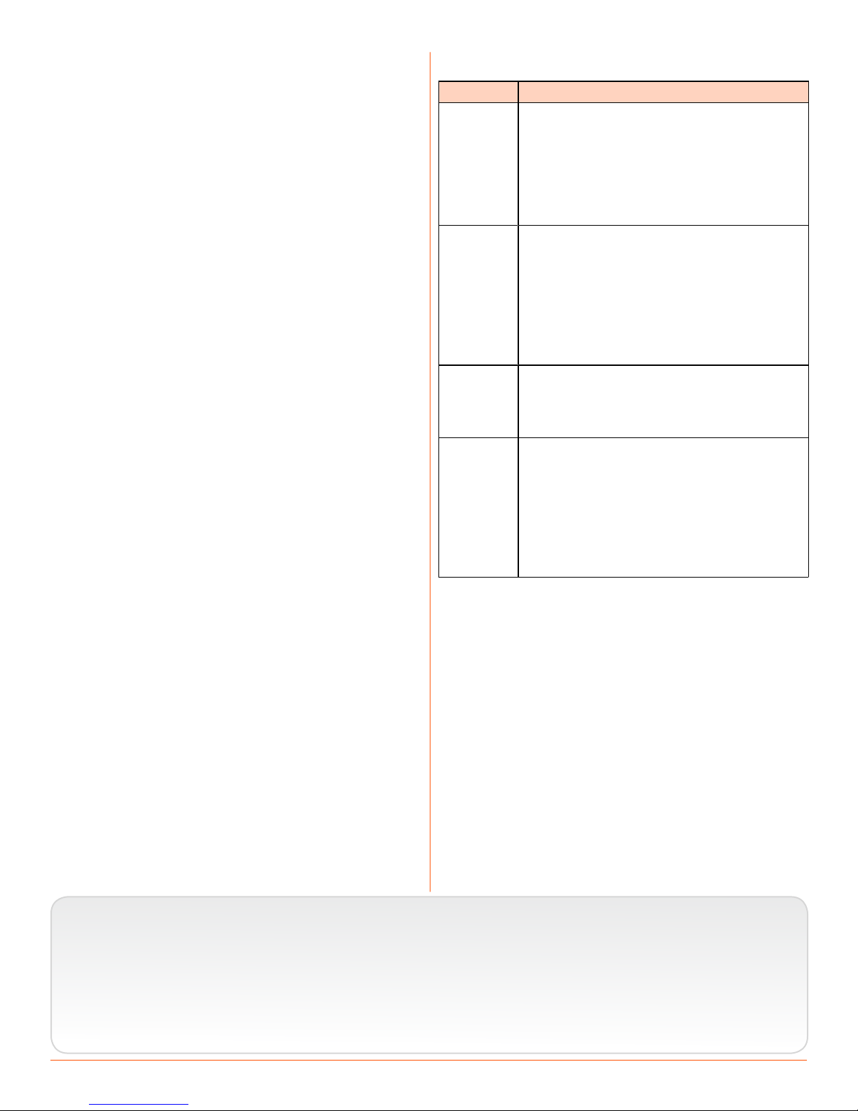
This table provides the revision history of this guide and includes notes for what changes were made.
Rev# Date Firmware
Version Description
1-A March 2015 v1.00 Initial Publication


5
Topics in this section include:
Overview of Chassis
Front, Top, and Bottom Panels
The 688 chassis is made of light-weight
and durable carbon-ber.
The front panel of the chassis features
several easy-to-reach controls,
switches, LEDs, and a sunlight-visible
LCD screen.
Its side panels provide a variety of
connection options for ultimate I/O
exibility. The top and bottom panels
offer additional connectors that allow
for expansion with optional accessories,
such as the SL-6 (on the top only) or
the CL-6 (on the bottom only).
Front panel
Top panel
The top panel of the chassis features the SL-6 multi-pin header connector used
with the optional SL-6 accessory. Similar to the top panel, the bottom panel
(not shown) features the CL-6 multi-pin header connector used with the op-
tional CL-6 accessory. Both connectors are located under removable protective
covers.
The front panel provides the LCD as well as several buttons, switches, and con-
trols as dened in the following tables.
Front, Top, and Bottom Panels
Left Side Panel
Right Side Panel
Back Panel

688 User’s Guide
6
Power Switch and LED
Menu Button
Headphone Encoder
Headphone Clipping LED
RTN/FAV SwitchMIC/TONE Switch
Slate/Tone LED
Select Encoder
Meters Button
Transport Control
Timecode LED
Feature Description
Power Switch and LED Powers 688 on and off, and indicates power status.
Timecode LED Flashes blue to indicate whether the internal timecode generator (and
QuickBoot) is active while the mixer is off.
Menu Button Provides access to the Main menu. Used for various shortcut
functions.
Headphone Encoder Adjusts headphone level and monitor source. Used for various shortcut
functions.
Headphone
Clipping LED
Illuminates red to indicate headphone output is approaching clipping
level.
RTN/FAV Switch Toggles monitor source. Can be customized or disabled in the Main
menu (Comms/Returns). Used for various shortcut functions.
MIC/TONE Switch Toggle slate mic and tone generator. Can be customized or disabled in
the Main menu (Comms/Returns). Used for various shortcut functions.
Slate/Tone LED Indicates slate mic is active or tone generator is locked on.
Select Encoder Multiple purpose rotary encoder. Used for various shortcut functions.
Meters Button Cycles between meter views. Used for various shortcut functions.
Transport Control Controls playback and recording. Used for various shortcut
functions.
Also on the front panel, there are six sets of controls related to inputs, such as
pans, faders, and trims.
Fader (1-6)
Pan (1-6)PFL (Left: 1-6, Right: 7-12)
Trim (1-6)
PFL status / Activity LED (7-12)
PFL status / Activity LED (1-6)
Mini-Fader (7-12)

7
OVERVIEW OF CHASSIS
Feature Description
PFL Switch By default, this switch has dual-functionality. It activates
Pre-Fade Listen (PFL) and displays Input Settings screen for
input 1-6 (slide left) and 7-12 (slide right). Slide again to
deactivate. The functionality of this switch may be altered
via the Main menu’s Inputs > PFL Toggle Mode.
Does not affect Master Output signal. For momentary ac-
tion, hold the switch for one second or longer. The input LED
ashes yellow when an input’s PFL is active.
iBecause the CL-6 accessory provides separate PFL switches
for inputs 7-12, when the CL-6 is attached to the 688, the
dual-functionality of the six PFL switches on the 668
changes. Slide left activates PFL and slide right displays
Input Settings for inputs 1-6 only.
Fader (1-6) Adjusts fader level for inputs 1-6.
Mini-Fader (7-12) Adjusts fader level for inputs 7-12.
iWhen the CL-6 accessory is attached to the 688, the
mini-faders become trim controls for inputs 7-12.
Trim (1-6) Adjusts trim level for inputs 1-6.
Pan (1-6) Adjusts pan between L and R tracks.
PFL status / Activity LED (1-6) Indicates PFL status and input signal activity.
PFL status / Activity LED (7-12) Indicates PFL status and input signal activity.
Left Side Panel
XLR Inputs
TA3 Inputs Headphone Outputs
Feature Description
XLR Inputs Active-balanced analog microphone- or line-level inputs. Inputs 1 and
6 can also accept AES3 or AES42 (Mode 1) signal.
Pin-1 = ground, pin-2 = hot (+), and pin-3 = cold (-).
TA3 Inputs Active-balanced analog line-level inputs.
Pin-1 = ground, pin-2 = hot (+), and pin-3 = cold (-).
Headphone Outputs 3.5mm and 1/4” headphone outputs. Can drive headphones from 8 to
1000 ohm impedances to very high levels.
Tip = left, ring = right, and sleeve = ground.

688 User’s Guide
8
Right Side Panel
10-pin A and C
SD Card Slot
CompactFlash SlotUSB B Connector
Battery CompartmentTimecode I/O DC InputMain OutputsRTN B InputTape Output
COM/RTN OutputX5 and X6 OutputsX1, X2, X3, and X4 Outputs
Feature Description
USB B Connector Factory use and keyboard connection (with adapter).
CompactFlash Slot Accepts approved CompactFlash cards with the label-side toward the
rear of the mixer. Compatible with Type I and Type II cards. High-
speed UDMA cards are recommended for higher track count recording.
10-pin A and C Each connection includes a pair of transformer-isolated Outputs and
a stereo unbalanced Return input. Analog Output levels are selected
between Line, -10, and Mic levels in Main menu OUTPUTS section.
10-pin A outputs can be set to AES Outputs 5,6 and 7,8 in Main menu
OUTPUTS section.
X1, X2, X3, X4 Out-
puts Line, -10, or Mic level selected in Main menu OUTPUTS section.
(Pin 1 = Ground, pin 2 = Hot (+), pin 3 = Cold (-))
Float pin 3 to unbalance.
X5, X6 Output Unbalanced stereo, tape level output on TA3 connector.
(Pin 1 = Ground, pin 2 = Left, pin 3 = Right)
COM/RTN Input Line-level input for return feed from on-set communications sources.
SD Card Slot Accepts SD/SDHC/SDXC cards with the notched corner oriented to-
ward the top of the 664. High speed class 10 cards are recommended.
Insert until it clicks securely in the slot. The card should glide smoothly
into the slot. Press to eject.
Timecode I/O Time code input and output on 5-pin LEMO® connector.
Tape Output Unbalanced stereo, tape level output on 3.5 mm connector.
(Sleeve = Ground, Tip = Left, Ring = Right)
RTN B Input Unbalanced stereo 3.5 mm female connector for Return B audio input.
(Sleeve = Ground, Tip = Left, Ring = Right.)
Main Outputs Transformer-balanced analog outputs on standard 3-pin XLR-3M con-
nectors. Can be set to send AES3 digital signals (1,2 and 3,4 on L and
R respectively) in Main menu OUTPUTS section.
(Pin 1 = Ground; pin 2 = Hot (+); pin 3 = Cold (-))
Unbalance by grounding pin 3 to pin 1.

9
OVERVIEW OF CHASSIS
Feature Description
Battery Compartment Holds ve AA (LR6) batteries for backup powering. NiMH rechargeable
cells advised.
DC Input Accepts DC voltages from 10–18 V for powering.
(Pin 1 = Negative (–), pin 4 = Positive (+))
Back Panel
The back panel contains BNC wordclock connections:
Wordclock Input Wordclock Output
Feature Description
Wordclock Input Accepts word clock rates between 44.1 kHz and 192 kHz for synchro-
nizing the internal recorder to external digital audio devices.
Wordclock Output Provides word clock signal to synchronize external digital audio de-
vices


11
Topics in this section include:
The LCD and User Interface
Meter Views
The LCD display is the primary source
of information when operating the 688.
All settings are congured via the LCD
display. All signal level meters can be
displayed on the LCD display.
This chapter describes meter views,
including the Main screen which is
displayed when no other screens
are active, the Main menu, and LCD
Daylight mode.
Other screens are described where
applicable throughout the guide.
The 688 displays important metering information at a glance on its LCD. All
meter views provide various combinations of input, track, and return meters. By
default, the rst of three predened meter views is shown. This view is known
as the Main screen.
Current Take
Active playback media
Media time remaining and audio le format
Power source and level
Input limiting activity
Monitor (Headphone) information.
RTN levelsSample rate information
Absolute recording time
SMPTE timecode
Powered off input
Armed track Unarmed track
Meter View
The three predened meter views are:
• LR, 1-12 — This meter view (shown above) shows left and right bus tracks
as well as all 12 input tracks.
• LR, X1, X2, RTNs — This meter view shows left, right, X1, and X2 bus
tracks, plus all returns.
• LR, X1-X6 — This meter view shows left and right bus tracks as well as sig-
nal from X1 through X6.
Meter Views
Using Meter Views
Customizing Meter Views
Accessing the Main Menu
Customizing the LCD and LEDs
Using LCD Daylight Mode

688 User’s Guide
12
The following images shows all three predened meter views.
iUse of the Mix Assist feature changes the appearance of the meters. For more in-
formation, see the chapter on Mix Assist.
Using Meter Views
Although the rst meter view is known as the Main screen, there are other
screens, which may appear on the LCD, such as the Main menu or the Input
Settings screen.
Regardless of what screen is visible, returning to the Main screen and its meter
view is easy.
To return to the main screen at any time:
XPress the METERS button.
You can also easily switch to any of three different meter views.
To toggle between the three meter views:
XPress the METERS button. Each press of the button switches the display to
the next view.
Customizing Meter Views
While the 688 provides three meter views by default, all three may be custom-
ized to display the information you deem most important.
To customize the meter views:
1. Press MENU.
2. Turn and press the Headphone encoder to select SYSTEM > Meter Views.
3. Select the meter view you would like to change.
4. Select the display option for that meter view.

13
THE LCD AND USER INTERFACE
Headphone Encoder
MENU Button
Accessing the Main Menu
The majority of the 688’s settings are congured with the Main
menu.
To access the Main menu:
XPress the MENU button.
The Main menu is made up of categories, each with its own set of sub-menu
options. Turn the Headphone encoder to navigate the Main menu and press it in
to select any category or sub-menu option.
While sub-menu options are covered in more detail throughout this guide in
sections related to those options, the Main menu’s categories are provided with
brief descriptions in the following table.
category Description
POWER Settings related to external power sources. Also displays voltage lev-
el of External DC, Internal DC (AA), and PowerSafe™.
INPUTS Settings related to channel linking, phantom power, PFL or Input
modes, input to ISO routing, and input delays.
OUTPUTS Settings related to output types or levels, output sources, output
routing, and output delays.
LIMITERS Settings related to input and output limiters.
MIXASSIST Allows MixAssist to be enabled or disabled and inputs to be added or
removed from MixAssist.
RECORDER Settings to target recording media, WAV sample rate / bit depth, MP3
bit rate, and recording pre-roll time.
COMMS/RETURNS Settings related to communications (Comm), including slate mic
(source, gain, routing), comm return gain, and RTN and FAV switch
actions.
TIMECODE/SYNC Settings related to timecode and sample clock synchronization.
FILE STORAGE Settings related to le storage and metadata.
SYSTEM Various system settings.
QUICK SETUP Allows user to save and recall user settings to and from SD, CF, and
internal memory. Also allows resetting all settings to factory default.

688 User’s Guide
14
Customizing the LCD and LEDs
Because the 688 is a portable eld mixer, it may be used in a variety of environ-
ments, including some where lighting is an issue that requires adjustments to
the mixer. With some System settings, you can modify the brightness levels of
the LCD, the brightness levels of the LEDs, and even enable or disable the LCD
Daylight mode.
To set the LCD brightness level:
1. Press the MENU button.
2. Turn and press the Headphone encoder to select SYSTEM > LCD Brightness.
3. Turn the Headphone encoder to change the value from 10 to 100%. Then
press the encoder to make your selection.
By default, the LCD brightness level is set to 100%.
To set the LCD brightness level:
1. Press the MENU button.
2. Turn and press the Headphone encoder to select SYSTEM > LED Brightness.
3. Turn the Headphone encoder to change the value from 5 to 100%. Then
press the encoder to make your selection.
By default, the LED brightness level is set to 60%.
Using LCD Daylight Mode
The default appearance of the LCD screen is a dark theme. However, a
lighter theme is available as an alternative mode, which can make viewing in
bright conditions easier. When enabled, the LCD Daylight mode may be toggled
between dark and light themes.
To enable or disable LCD Daylight mode:
1. Press the MENU button.
2. Turn and press the Headphone encoder to select SYSTEM > LCD Daylight
Mode.
3. Do one of the following:
XSelect On to enable.
XSelect Off to disable.
To toggle LCD Daylight mode:
XSELECT + HP: simultaneously press the SELECT and Headphone encoders.

17
Topics in this section include:
Headphone Monitoring
Connecting Headphones
The 688 provides two headphone
outputs on its left panel, several options
for headphone sources including up to
10 custom presets, plus a variety of
other customizable features related to
audio monitoring.
Connect headphones to either the 1/4-inch or 3.5mm head-
phone outputs, located on the left panel of the 688.
⚠The 688 can drive headphones to dangerously high vol-
umes. Turn down the headphone gain before attaching
headphones or selecting a headphone source to prevent
accidental high levels.
To adjust Headphone gain:
XTurn the Headphone encoder.
Selecting Headphone Source
The default list of headphone presets consists of six predened headphone
sources and 10 customizable presets.
To select a headphone source:
1. Press the Headphone encoder to display the list of available sources.
2. Turn the encoder to change the headphone source. Options include: LR ST,
LR Mono, L Mono, R Mono, LR MS ST, X1X2, and HP Preset (1) through HP
1/4”
3.5mm
Connecting Headphones
Selecting Headphone Source
Headphone Encoder Mode
Configuring the Headphone Preset List
Defining Custom Headphone Presets
Choosing a Favorite Headphone Preset
Headphone Source Shortcuts
Headphone Peak LED

688 User’s Guide
18
Preset (10).
The headphone source changes immediately as it is highlighted in the list.
3. Press the encoder to close the list.
Headphone Encoder Mode
The default functionality of the Headphone encoder can be reversed so that the
Headphone encoder must be pressed before turning to adjust the headphone
volume, and headphone source can be selected by simply turning the Head-
phone encoder.
To set Headphone Encoder mode:
1. Press the MENU button.
2. Turn and press the Headphone encoder to select SYSTEM > Headphone En-
coder Mode > Preset/Vol.
Configuring the Headphone Preset List
Presets can be excluded from this list to make preset selection simpler.
To edit the Headphone Preset list:
1. Press the MENU button.
2. Turn and press the Headphone encoder to select SYSTEM > Headphone Pre-
set List.
The Headphone Preset List will be displayed; presets with a blue back-
ground are visible, and presets with a black background are hidden.
3. Turn and press the Headphone encoder to toggle the visibility of each pre-
set.
Defining Custom Headphone Presets
In addition to the six predened headphone sources, 10 options are available as
custom headphone presets.
To customize a headphone preset:
1. Press the Headphone encoder to display the list of available sources.
2. Turn the encoder to choose one of the 10 customizable preset options, such
as HP Preset(1).
3. Slide the MIC/TONE switch left or right.
The Headphone Preset Editing screen appears.

19
HEADPHONE MONITORING
Pre-fade routing
Post-fade routing
Unrouted source
Right HPLeft HP
4. Do one of the following:
XTurn the Headphone encoder to move the orange highlight horizontally.
XTurn the Select encoder to move the orange highlight vertically.
5. Press the Headphone or Select encoder to change the selected source be-
tween Off (black), Post-fade (blue), and Pre-fade (green).
iOnly ISO sources have the pre-fade option.
6. (Optional) Do any of the following:
XSlide the MIC/TONE switch left to toggle MS decoding for this head-
phone preset.
XSlide the MIC/TONE switch right to toggle mono summing for this head-
phone preset (All active sources will be summed into both headphone
channels).
XSlide the RTN/FAV switch left to name the headphone preset.
XSlide the RTN/FAV switch right to toggle the favorite status of this head-
phone preset.
7. Press MENU or METERS to save the preset and exit the Headphone Preset
Editing screen.
iOnly one preset at a time can be set as a favorite. Marking a preset as favorite will
remove the favorite status of all other presets.
Choosing a Favorite Headphone Preset
A single headphone preset can be designated as a favorite. This favorite head-
phone preset can be quickly accessed via the front panel.
To choose a predened Headphone preset as favorite:
1. Press the Headphone encoder to display the list of available sources.
2. Turn the Headphone encoder to highlight the predened preset you want.
Options include: LR ST, LR Mono, L Mono, R Mono, LR MS ST, and X1X2.
3. Slide the RTN/FAV switch right to set the highlighted Headphone preset as
your new favorite.

688 User’s Guide
20
Headphone Source Shortcuts
There are a total of four headphone monitor shortcuts on the 688. By default,
these shortcuts go to: RTN A, RTN B, COM RTN, and the headphone source set
as favorite.
To monitor RTN A:
XSlide the RTN/FAV switch to the left.
To monitor RTN B:
XHold down the Select encoder and simultaneously slide the RTN/FAV switch
to the right.
To monitor COM RTN:
XHold down the Select encoder and simultaneously slide the RTN/FAV switch
to the left.
To monitor the favorite headphone source:
XSlide the RTN/FAV switch to the right.
iThese are the default headphone source shortcuts. These shortcuts may be cus-
tomized via the Main menu’s COMMS/RETURNS settings.
Headphone Peak LED
The Headphone Peak LED, located just left of the Headphone encoder, illumi-
nates red to indicate headphone output is approaching clipping level. Monitoring
without a visual indication of headphone clipping can mislead a sound mixer
into thinking the output or return feeds are distorted.

21
Topics in this section include:
Power
The 688 utilizes different powering
options, such as external DC power, or
it may be powered by ve AA batteries.
When used with the SL-6 accessory, an
optional powering and wireless system,
the 688 may be powered via an NP1
battery.
The 688 also incorporates exclusive
PowerSafe™ technology with smart
sensing of available power sources,
front panel power warning indication,
and an integrated 10-second power
reserve that safely stops recording and
shuts down in the event of a power loss.
Power LED
The 688 operates on either external DC power or internal AA battery power.
To turn on the 688:
XFlip the Power switch to the ON position.
The Power LED illuminates yellow then green. The Sound
Devices splash screen appears briey on the LCD, and then the
Main screen is displayed.
As part of the Main screen, the LCD displays a DC voltage indi-
cator in the form of a battery icon that indicates the level of the
power source (internal or external) currently in use.
Normal Voltage (Green)
Warning Voltage (Yellow) Low Voltage (Orange) Critical Voltage (Red)
Using External Power
The 688 uses only one power source at a time, with external DC power taking
precedence over internal AA battery power.
Powering the 688
Using External Power
Using Battery Power
Voltage Ranges and Thresholds
PowerSafe™
QuickBoot
Forcing Power Off (Optional)
Power Consumption
Powering the 688

688 User’s Guide
22
To connect an external power source:
XPlug a DC power source (not included) into the 10-18 VDC input on the
right panel.
iPin-4 of the locking, Hirose connector is positive (+) and pin-1 is negative (-).
Using Battery Power
The 688 uses ve AA batteries as a backup to external power. Alkaline AA bat-
teries may be used with the 688; however, NiMH batteries are the preferred
type because they provide for longer run times compared to Alkaline batteries.
To insert batteries:
1. Unscrew the battery cap (counter-clockwise).
2. Insert ve AA NiMH batteries (not included) into the battery tube. Orient
the batteries with the positive (+) end facing in and the negative (-) end
facing out.
iWith external power connected, depleted AA batteries may be removed from the
688 and replaced with new ones without affecting operations.
Voltage Ranges and Thresholds
The DC voltage indicator provides power status information based on the Ex-
ternal DC Reference parameter, which denes the voltage range and warning
threshold for external DC power sources. Setting the External DC Reference to a
value appropriate for the type of external power being used maximizes runtime
with that source.
For instance, the indicator appears solid green when the active power source is
full or operating within the dened high voltage range. As the voltage depletes,
the indicator’s color changes from green to yellow (warning) to orange (low)
and to red (critical), based on the external power source’s range and threshold,
as shown in the following table:
ext Dc reF Low VoLtage warning VoLtage HigH VoLtage
12V Ext DC 9 10 11
NiMH 11 11.5 13
Expanded NiMH 11 11.5 18
12V Lead Acid 10 11.4 14
14V Li-ion 12.5 13.5 16.3
Full Range 6 11.5 18
If the active power source is removed or its voltage drops to the critical thresh-
old, the 688 switches to alternative battery power or shuts down, according to
how its External DC Loss parameter is congured in the Power settings.
Other manuals for 688
4
Table of contents
Other Sound Devices Music Mixer manuals

Sound Devices
Sound Devices 664 Manual

Sound Devices
Sound Devices 633 Manual

Sound Devices
Sound Devices 664 Manual

Sound Devices
Sound Devices MixPre-10M User manual

Sound Devices
Sound Devices MixPre Manual

Sound Devices
Sound Devices 664 User manual

Sound Devices
Sound Devices 664 User manual

Sound Devices
Sound Devices 633 User manual

Sound Devices
Sound Devices 664 User manual

Sound Devices
Sound Devices 633 User manual


