Sistemes Electrònics Progrés s.a. 06750001 User manual

H2O Transmitter
Manual
Transmitter for reading soil water content sensors (VWC: Volumetric Water Content)
or wet leaves (LWS: Leaf Wetness Sensor).
H2O Transmitter
H2O Transmitter
3-level VWC sensor
It oers the following benefits:
• Reading of up to three sensors of this type:
‒ Decagon 10HS (VWC)
‒ Decagon EC5 (VWC)
‒ Meter Group TEROS-10 (VWC)
• Reading such a sensor:
‒ Meter Group PHYTOS-31
• The transmitter adapts the signals coming from the sensors and generates an output in
standard 4-20mA current values.
From the transmitter itself, the number and type of sensors and the soil variety can be configu-
red by using a Module Reader.
The transmitter supplies each sensor with the necessary supply voltage depending on the type
of sensor configured internally.
All sensors connected to the same transmitter must always be of the same type.
CODE 2 SENSORS 06750001 | 3 SENSORS 06750002
Leaf wetness sensor

2· User manual | H2O Transmitter
Technical characteristics
Power supply 12 Vdc to 20 Vdc
Energy consumption 3 sensors: less than 0’9 W
Surge fuse Input Thermal (PTC) 0’4 A at
25 ° C self-resetting
Reverse Current Protection: Yes
Output sign 4 – 20 mA 1, 2 o 3 outputs
Sensor power supply 3 Vdc to 12 Vdc 1, 2 o 3 outputs
Power supply
Outputs
Minimum transmitter power supply time before receiving reading:
1 sensor: 250 ms 2 sensors: 400 ms 3 sensors: 500 ms
Response time
Number 1, 2 or 3
Type Analogue (12 bits)
Inputs
Environment
Height 99 mm
Width 65 mm
Depth 39 mm
Weight (approx.) 0,4 Kg
Transmitter box dimensions
Transmitter power (12 Vdc, with 2x1.5mm2 cable):
1 sensor: 225 metres 2 sensors: 150 metres 3 sensors: 100 metres
From sensor to transmitter: 30 metres
4-20 mA current output: 1000 metres
Maximum distance
This symbol indicates that electrical and electronic equipment should not be disposed of along
with household waste at the end of its useful life. The product must be taken to the correspon-
ding collection point for recycling and proper treatment of electrical and electronic equipment
in accordance with national legislation.
Temperature -10 °C to +60 °C
Degree of protection IP65
Moisture < 95 %
Height 2000 m
Pollution Grade II

User manual | H2O Transmitter · 3
Surface fastening
hole
Surface fastening
hole
• The transmitter should be positioned horizontally, so that moisture does not accumulate at
the ends.
• The transmitter should be placed in a location that is not directly exposed to the sun.
• It is absolutely necessary to keep the box water-tight.
• Feed the hose cable through the stuing box and tighten it as well as you can.
• Do not place the transmitter cables next to power lines.
Installation
Connecting
The transmitter is provided with two 1.5m cable hoses that allow you to make dierent connec-
tions more easily without the need to access the interior.
3 SENSORS2 SENSORS

4· User manual | H2O Transmitter
Consult the manual of each sensor for detailed information about its installation and
connection.
H2O Transmitter
Watertight
connection
terminals Sensor
To guarantee the water-tightness of the
connections of the wires in the module hose,
using watertight terminals is recommended.
The connection through these terminals must
be made without stripping the cable wires.
The 3M Scotchlok series (www.3m.com);
ES Caps from TYCO Electronics (www.
tycoelectronics.com); or Cellpack resin splice
and derivation kits (www.cellpackiberica.
com) can be used as connection elements.
6-wire power supply and current output connection hose:
Power supply and current output
Wire colour ID Function 1 sensor 2 sensors 3 sensors
White 0V - (negative) of power supply x x x
Brown 12V + (positive) of power supply x x x
Green S1 Output 1: 4 - 20 mA x x x
Yellow S2 Output 2: 4 - 20 mA x x
Grey S3 Output 3: 4 - 20 mA x
Sensor connection hose, 6-wire (2 sensors) or 9-wire (3 sensors):
Sensor connection
Wire colour ID Function 1 sensor 2 sensors 3 sensors
White A1 Analogue sensor input 1 x x x
Brown 0V Common sensor power supply xxx
Green VA1 Sensor 1 power supply x x x
Yellow A2 Analogue sensor input 2 x x
Grey 0V Common sensor power supply x x
Pink VA2 Sensor 2 power supply x x
Blue A3 Analogue sensor input 3 x
Red 0V Common sensor power supply x
Black VA3 Sensor 3 power supply x
It is recommended that loose cables also be connected with an excess of 3M of
connector to avoid possible short circuits or from them getting wet.
NOTE

User manual | H2O Transmitter · 5
Conguration
The transmitters are generally configured at the factory. However,
it is possible to make consultations or configurations through the
use of a “Module Reader,” consisting of a screen and four keys that
are connected to the transmitter through the only interior visible
connector.
Press the key to enter the main menu.
With the + and keys, you can change the options within
the menu. With the key, you can enter the selected menu
option.
With the key, you can return to the menu option of the
previous hierarchy.
Within the main menu, you can see the following options:
• Consultation
• Configuration
+-
cc
Transmitter’s general consultation menu, where you can view:
• Controller firmware version No.
• Transmitter type (depending on the sensor used).
• Consultation of the value, in mV, that the sensors deliver, (from input 1 (A1) to input 3 (A3)).
• Consultation of the 4-20 mA current value being delivered (output of 1 to 3).
CONSULTATION MENU
Configuration menu of the dierent transmit-
ters according to the type of sensor.
For each sensor, you can configure the number
of sensors that are read and the type of soil.
• No. Inputs: 1, 2, or 3
• Soil: Mineral or Potting Soil
CONFIGURATION MENU
Soil selection table according to sensor
Sensor Mineral
soil Potting
soil
10HS Decagon x x
PHYTOS-31 Meter Group x
EC-5 Decagon x x
TEROS-10 Meter Group x x

6· User manual | H2O Transmitter
H2O ANALOGUE SENSOR FORMAT
The possibility of selecting one soil type or another is determined by the manufacturer of each
of the sensors. Being able to make this selection allows the H2O transmitter to carry out one
process or another with the sensor readings, as recommended by the manufacturer itself:
• 10HS Decagon The sensor gives you a voltage x[mV] that the H2O transmitter converts into
VWC [%] (Volumetric Water Content) using the following equation:
VWC [%] = fx5+ex4+dx3+cx2+bx+a, and depending on the type of soil:
Mineral soil:
∙ a = -1.92
∙ b = +6.69E-3
∙ c = -7.37E-6
∙ d = +2.97E-9
∙ e = 0
∙ f = 0
Sensor format 10HS
Parameter Default value
No. of integers 2
No. of decimals 1
Sign no
Units %
Calibration point 1
Real value 800 mV
Logical value 00.0 %
Calibration point 2
Real value 4000 mV
Logical value 50.0 %
‒ Potting soil:
∙ a = -0.03
∙ b = -1.23E-4
∙ c = +7.05E-7
∙ d = 0
∙ e = 0
∙ f = 0
The value in [%] is converted, by the transmitter itself, to standard 4-20 mA current (800-4000
mV in Agrónic format), so that, in the controller in question, it is necessary to select the Ideal data
format according to the type of sensor and type of soil selected. It is the responsibility of the user
to change the data that characterizes said format.
• PHYTOS-31 Meter Group This sensor is for
the measurement of moisture on the leaf’s
surface (LWS: Leaf Wetness Sensor) and
delivers a value between 10% and 50% of its
supply voltage. The H2O transmitter delivers
a supply voltage of 5V, so the value that this
sensor will deliver will range between 500
mV (0%) and 2500 mV (100%). This value, in
%, is converted by the transmitter to 4-20 mA
current (800mV - 4000mV in Agrónic format).
Sensor format PHYTOS-31
Parameter Default value
No. of integers 3
No. of decimals 0
Sign no
Units %
Calibration point 1
Real value 800 mV
Logical value 000 %
Calibration point 2
Real value 4000 mV
Logical value 100 %

User manual | H2O Transmitter · 7
Sensor format EC-5
Parameter Default value
No. of integers 3
No. of decimals 1
Sign no
Units %
Calibration point 1
Real value 800 mV
Logical value 00.0 %
Calibration point 2
Real value 4000 mV
Logical value 100.0 %
• EC-5 Decagon Decagon The sensor delivers a
voltage x[mV]thattheH2O transmittertransforms
into VWC [%] (Volumetric Water Content or Soil
Water Content) using the following expression:
VWC [%] = bx+a, and according to soil type:
‒ Mineral soil:
∙ a = -0.48
∙ b = +11.605E-4
‒ Potting soil:
∙ a = -0.696
∙ b = +17.749E-4
The value, in [%], is converted, by the transmitter
itself, to standard 4-20 mA current (800-4000 mV in
Agrónic format), so that the controller in question
must select the Ideal data format according to the
type of sensor and type of soil selected. It is the res-
ponsibility of the user to change the data that charac-
terizes said format.
Sensor format TEROS-10
Parameter Default value
No. of integers 2
No. of decimals 1
Sign no
Units %
Calibration point 1
Real value 800 mV
Logical value 00.0 %
Calibration point 2
Real value 4000 mV
Logical value 70.0 %
• TEROS-10 Meter Group The sensor delivers a
voltage x[mV] that the H2O transmitter transforms
into VWC [%] (Volumetric Water Content or Soil
Water Content) using the following expression:
VWC [%] = dx3+cx2+bx+a , and according to the
soil type:
‒ Mineral soil:
∙ a = -2.154
∙ b = +3.898E-3
∙ c = -2.278E-6
∙ d = +4.824E-10
‒ Potting soil:
∙ a = -2.683
∙ b = +4.868E-3
∙ c = -2.731E-6
∙ d = +5.439E-10
The value in [%] is converted, by the transmitter itself, to standard 4-20 mA current (800-4000
mV in Agrónic format), so that, in the controller in question, it is necessary to select the Ideal
data format according to the type of sensor and type of soil selected. It is the responsibility of the
user to change the data that characterizes said format.

R-2247-1
Polígon Industrial, C/ de la Coma, 2 | 25243 El Palau d’Anglesola | Lleida | España
Tel. +34 973 32 04 29 | info@progres.es | www.progres.es
Sistemes Electrònics Progrés, S.A.
This manual suits for next models
1
Table of contents
Popular Transmitter manuals by other brands

Me
Me BELL-219 TX instruction manual
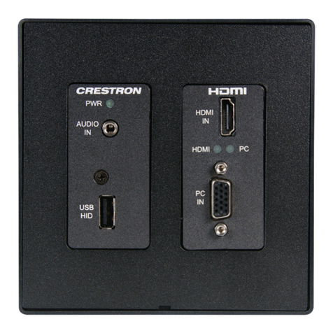
Crestron
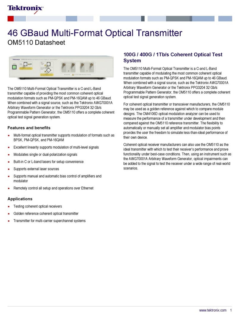
Crestron DM-TX-200 Operations & installation guide

Endress+Hauser
Endress+Hauser CUM 740 operating instructions
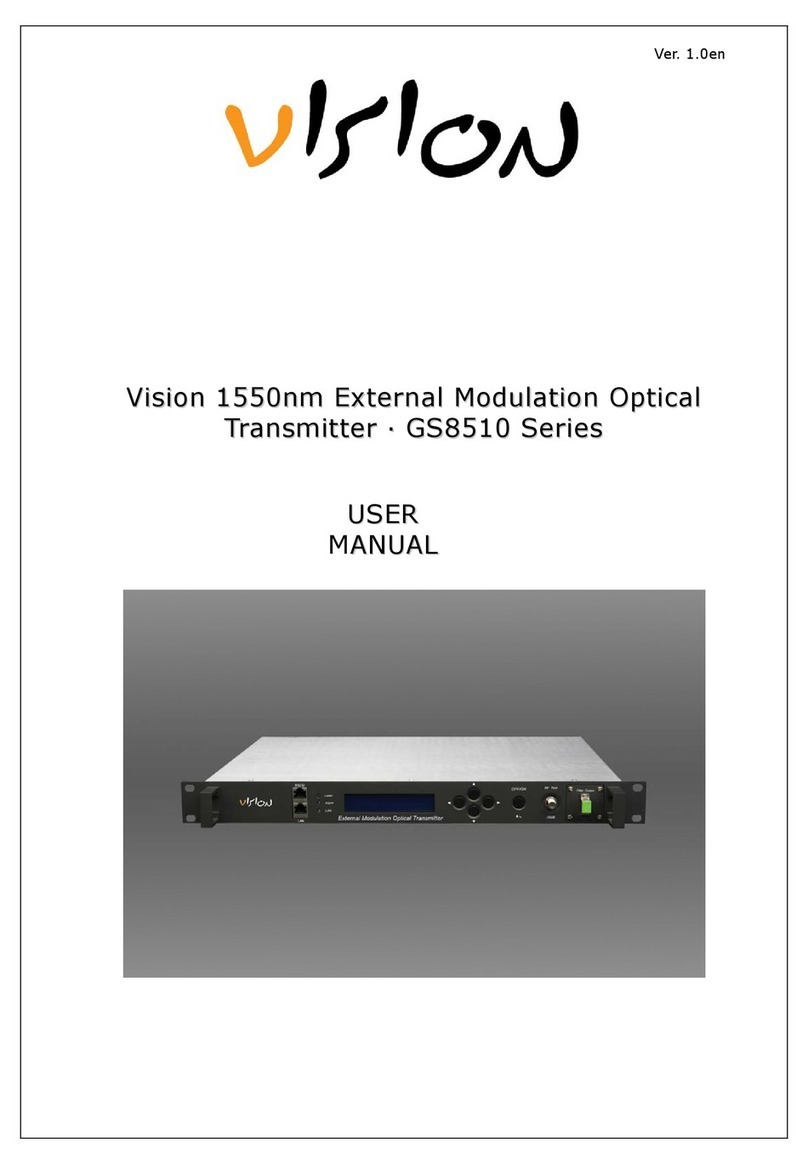
Vision
Vision GS8510 Series user manual
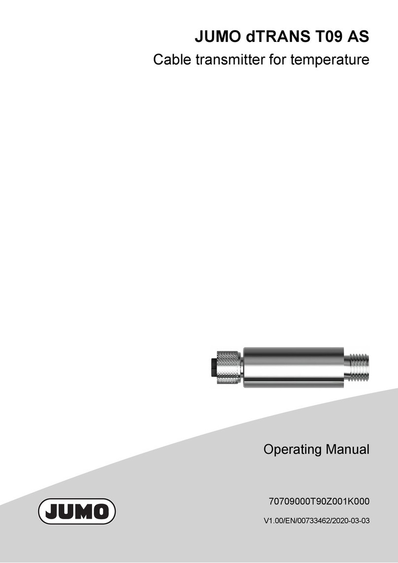
JUMO
JUMO dTRANS T09 AS operating manual
CETC Maritime Electronics
CETC Maritime Electronics VAI8 Operation and installation manual

