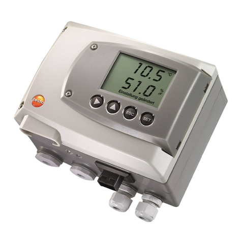
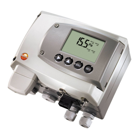
TESTO 6321 User manual

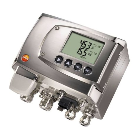
testo 6321 · differential pressure transmitter
P2A software · Parameterizing, adjusting and analyzing
software
Instruction manual
www.GlobalTestSupply.com
Find Quality Products Online at: sales@GlobalTestSupply.com

1 Safety and the environment
3
Pos: 1 /TD/Übersc hriften/MUF/Sic herheit und Umwel t @ 3\mod_1234793958627_7 9.doc @ 26223 @ 1
1Safety and the environment
Pos: 2 /TD/Sic herheit und Umwelt/Sicher heit gewährleisten/ MUF 63xx/Elektri sche Gefahren vermeiden @ 3\mod_1234 794609299_79.doc @ 26280 @ 5
Avoiding electrical hazards
> Never use the instrument and connected probes to measure on
or near live parts!
> Damaged mains cables must only be replaced by authorized
personnel.
> Only have the transmitter wired and connected by authorized
personnel with the voltage disconnected.
> You must always comply with the regulations applicable in your
country for opening and repairing electrical equipment.
Pos: 3 /TD/Sic herheit und Umwelt/Si cherheit gewährlei sten/MUF 63xx/Per sonen- und Sachschäden ver meiden @ 3\mod_1234794744 768_79.doc @ 26299 @ 5
Avoiding personal injury and damage to equipment
> Installation, setting and calibration work must only be carried
out by qualified and authorized personnel!
> Only open the instrument when this is expressly described in
the instruction manual for installation, maintenance or repair
purposes.
> Observe the permissible storage, transport and operating
temperature.
Pos: 4 /TD/Sic herheit und Umwelt/Si cherheit gewährlei sten/Nicht mit Lös ungsmitteln lag ern @ 0\mod_117569237517 9_79.doc @ 583 @
> Do not store the product together with solvents. Do not use any
desiccants.
Pos: 5 /TD/Sic herheit und Umwelt/Sicher heit gewährleisten/ MUF 63xx/Bei War tungM UFni cht zur Regelung verwende n @ 3\mod_1234794852377_79. doc @ 26318 @
> Do not use the instrument for control purposes at the same time
as operating or servicing the transmitter.
Pos: 6 /TD/Sic herheit und Umwelt/Si cherheit gewährlei sten/Produkt besti mmungsgemäß ver wenden @ 0\mod_117378126 1848_79.doc @ 386 @
> Only operate the product properly, for its intended purpose and
within the parameters specified in the technical data. Do not
use any force.
Pos: 7 /TD/Sic herheit und Umwelt/Sicher heit gewährleisten/ Nur beschriebene War tungsarbeiten durc hführen @ 0\mod_1175692705195 _79.doc @ 601 @
> Carry out only the maintenance and repair work on this
instrument that is described in the documentation. Follow the
prescribed steps exactly. Use only original spare parts from
Testo.
Pos: 8 /TD/Sic herheit und Umwelt/Si cherheit gewähr leisten/MUF 63xx/Fac hpersonal @ 3\mod_1234 794940409_79.doc @ 26337 @
Any additional work must only be carried out by authorized
personnel. Otherwise testo will not accept any responsibility for the
proper functioning of the instrument after repair and for the validity
of certifications.
www.GlobalTestSupply.com
Find Quality Products Online at: sales@GlobalTestSupply.com

2 About this document
4
Pos: 9 /TD/Übersc hriften/MUF/Umwelt sc hützen @ 3\mod_12348587575 71_79.doc @ 26363 @ 5
Protecting the environment
Pos: 10 /TD/Sic herheit und Umwelt/ Umwelt schützen/Pr odukt entsorgen @ 0\mod_ 1173780307072_ 79.doc @ 357 @
> At the end of its useful life, send the product to the separate
collection for electric and electronic devices (observe local
regulations) or return the product to Testo for disposal.
Pos: 11 /TD/Übersc hriften/MUF/Zu diese m Dokument @ 3\mod_123479399133 1_79.doc @ 26242 @ 1
2About this document
Pos: 12 /TD/Sic herheit und Umwelt/Zu diese m Dokument/Verwendun g (Standard) @ 0\mod_1173775068 554_79.doc @ 337 @ 5
Use
> Please read this documentation through carefully and
familiarize yourself with the product before putting it to use. Pay
particular attention to the safety instructions and warning advice
in order to prevent injuries and damage to the products.
> Keep this document to hand so that you can refer to it when
necessary.
> Hand this documentation on to any subsequent users of the
product.
Pos: 13 /TD/Sic herheit und Umwelt/Zu diese m Dokument/Symbole und Sc hreibkonventione n/Warnhinweis WA RNUNG@ 2\mod_12 07646966234_79. doc @ 14398 @
WARNING Indicates potential serious injuries
Pos: 14 /TD/Sic herheit und Umwelt/Zu diese m Dokument/Symbole und Sc hreibkonventione n/Warnhinweis VORSIC HT@ 2\mod_1 207651416515_79.d oc @ 14416 @
CAUTION indicates potential minor injuries
Pos: 15 /TD/Sic herheit und Umwelt/Zu diese m Dokument/Symbole und Sc hreibkonv. Soft ware [Standard] @ 0\mod_119020333 2543_79.doc @ 4883 @ 5
Symbols and writing standards
Representa-
tion
Explanation
Note: Basic or further information.
1. ...
2. ...
Action: more steps, the sequence must be
followed.
> ... Action: a step or an optional step.
- ... Result of an action.
Menu Elements of the program interface.
[OK] Buttons of the program interface.
... | ... Functions/paths within a menu.
“...” Example entries
Pos: 16 /TD/--- Seitenwechsel --- @ 0\mod_1173774 430601_0.doc @ 283 @
www.GlobalTestSupply.com
Find Quality Products Online at: sales@GlobalTestSupply.com

3 Contents
5
Pos: 17 /TD/Übersc hriften/MUF/Inh alt @ 3\mod_1234794019 831_79.doc @ 26261 @ 1
3Contents
1Safety and the environment....................................................................3
2About this document...............................................................................4
3Contents ...................................................................................................5
4Transmitter...............................................................................................7
4.1. Specifications ..................................................................................7
4.1.1. Functions and use ...........................................................................................7
4.1.2. Scope of delivery .............................................................................................7
4.1.3. Dimensions......................................................................................................7
4.1.4. Technical data .................................................................................................7
4.2. Product description........................................................................11
4.2.1. At a glance.....................................................................................................11
4.2.2. Scaling .........................................................................................................12
4.3. Commissioning ..............................................................................13
4.3.1. Assembling the instrument.............................................................................13
4.3.1.1. Wall mounting ...................................................................................13
4.3.2.Wiring the instrument.....................................................................................14
4.3.2.1. 4-wire system....................................................................................16
4.3.2.2. 3-wire system....................................................................................16
4.4. Maintenance and cleaning.............................................................17
4.4.1. Cleaning housing ...........................................................................................17
4.4.2. Namur fault conditions ...................................................................................17
5Parameterizing, adjusting and analyzing software (P2A software)...18
5.1. Specifications ................................................................................18
5.1.1. Functions and use .........................................................................................18
5.1.2. System requirements.....................................................................................19
5.1.3. Scope of delivery ...........................................................................................19
5.2. First steps......................................................................................20
5.2.1. Installing the software/driver ..........................................................................20
5.2.1.1. Installing P2A software......................................................................20
5.2.1.2. Installing USB driver .........................................................................20
5.2.1.3. P2A software upgrade ......................................................................20
5.2.2. Starting the software......................................................................................20
5.2.2.1. Starting the program .........................................................................20
5.2.2.2. Establishing a connection with the instrument...................................20
5.2.2.3. Activating the connection with the instrument....................................21
www.GlobalTestSupply.com
Find Quality Products Online at: sales@GlobalTestSupply.com
3 Contents
6
5.3. Using the software ........................................................................ 21
5.3.1. User interface ................................................................................................ 21
5.3.2. Editing instrument/parameter file ................................................................... 24
5.3.2.1. Changing instrument/parameter file .................................................. 24
5.3.2.2. Creating a new instrument file........................................................... 26
5.3.2.3. Saving parameters............................................................................ 26
5.3.2.4. Opening the parameter file ............................................................... 26
5.3.2.5. Copying and pasting parameters ...................................................... 27
5.3.2.6. Deleting instrument/parameter file .................................................... 27
5.3.3. Analyzing/testing the transmitter.................................................................... 27
5.3.3.1. Analyzing/testing the instrument ....................................................... 28
5.3.3.2. Carrying out factory reset.................................................................. 28
5.3.3.3. Testing analog output ....................................................................... 28
5.3.3.4. Displaying min./max. values.............................................................. 30
5.3.4. Adjusting the transmitter ................................................................................ 31
5.3.4.1. n-point adjustment ............................................................................ 31
5.3.4.2. Adjusting the analog output .............................................................. 32
5.3.5. Transmitter history......................................................................................... 33
6Tips and assistance .............................................................................. 36
6.1. Questions and answers ................................................................ 36
6.2. Accessories and spare parts......................................................... 36
6.2.1. Ordering options for testo 6321 transmitter (0555 6321)................................ 37
Pos: 18 /TD/--- Seitenwechs el --- @ 0\mod_1173774430601_0.doc @ 283 @
www.GlobalTestSupply.com
Find Quality Products Online at: sales@GlobalTestSupply.com
4 Transmitter
7
Pos: 19 /TD/Übersc hriften/MUF/1 Messu mformer @ 3\mod_1234258401060 _79.doc @ 23894 @ 1
4Transmitter
Pos: 20 /TD/Übersc hriften/MUF/1.1/2. 1/3.1 Leistungsbe schreibung @ 3\mod_123425 8595211_79.doc @ 23951 @ 2
4.1. Specifications
Pos: 21 /TD/Leis tungsbeschreibung/Ver wendung/MUF63 xx/MUF 6321 @ 3\mod_1241608910962_7 9.doc @ 32625 @ 3
4.1.1. Functions and use
The testo 6321 transmitter is suitable for the following applications,
amongst others:
•Air conditioning and ventilation technology
◦Monitoring ventilation and filtration systems
◦Monitoring fans
◦Monitoring exhaust air volumetric flow rates
Pos: 22 /TD/Leis tungsbeschreibung/Li eferumfang/MUF 63 xx/MUF 6781 @ 3\mod_1238162497 483_79.doc @ 30275 @ 3
4.1.2. Scope of delivery
The scope of delivery of the testo 6321 transmitter includes the
following:
•Assembly accessories
•Operating instructions
•Calibration report
Pos: 23 /TD/Leis tungsbeschreibung/ Technische Daten/ MUF63 xx/MUF 6781 Abmessungen @ 3\mod_12 39806330094 _79.doc @ 31183 @ 3
4.1.3. Dimensions
Pos: 24 /TD/Leis tungsbeschreibung/ Technische Daten/ MUF63 xx/MUF 6321 @ 3\mod_ 1241601145321 _79.doc @ 32604 @ 3555555555 5555555555
4.1.4. Technical data
Parameter
•Differential pressure
www.GlobalTestSupply.com
Find Quality Products Online at: sales@GlobalTestSupply.com
4 Transmitter
8
Accuracy1
The specifications are only valid if the positive pressure is
applied at the positive pressure connection.
•1.2 % of measuring range, additional ±0.3 Pa intrinsic error 2
•TK slope drift = 0.05 % of measuring range per degree Kelvin of
deviation from nominal temperature 22 °C
•TK zeroing drift= 0 % (by means of automatic zeroing)
Measuring range, resolution and overload
Measuring range
depending on
version ordered
Resolution Overload
0 to 100 Pa 0.1 Pa 20,000 Pa
0 to 10 hPa 0.01 hPa 200 hPa
0 to 20 hPa 0.01 hPa 200 hPa
0 to 50 hPa 0.01 hPa 750 hPa
0 to 100 hPa 0.1 hPa 750 hPa
0 to 500 hPa 0.1 hPa 2500 hPa
0 to 1000 hPa 1 hPa 2500 hPa
0 to 2000 hPa 1 hPa 2500 hPa
-100 to 100 Pa 0.1 Pa 20,000 Pa
-10 to 10 hPa 0.01 hPa 200 hPa
-20 to 20 hPa 0.01 hPa 200 hPa
1At 25 °C. A stabilization period of approx. 30 min must be taken into account
upon commissioning the instrument.
2Measuring uncertainty in accordance with GUM: ±1.2 % of measuring range
final value ±0.3 Pa.
GUM (Guide to the Expression of Uncertainty in Measurement): ISO guideline for determining the
measuring uncertainty in order to render global measurement results comparable.
The following uncertainties are used during the inquiry:
•Hysteresis
•Linearity
•Reproducibility
•Long-term stability
•Adjustment area/factory calibration
•Test location
www.GlobalTestSupply.com
Find Quality Products Online at: sales@GlobalTestSupply.com
4 Transmitter
9
Measuring range
depending on
version ordered
Resolution Overload
-50 to 50 hPa 0.01 hPa 750 hPa
-100 to 100 hPa 0.1 hPa 750 hPa
-500 to 500 hPa 0.1 hPa 2500 hPa
-1000 to 1000 hPa 1 hPa 2500 hPa
-2000 to 2000 hPa 1 hPa 2500 hPa
Upon delivery and following a factory reset the readings are
shown in the display in the unit that was ordered via the
KMAT option Fxx, see Ordering options for testo 6321
transmitter (0555 6321) page 37.
Meas. cycle
•1/sec
Zeroing cycle
•Set to 1 min at the factory
Interface
•Mini-DIN for P2A software (adjustment and parameterization
software)
Voltage supply
•3 or 4-wire (separate signal and supply lines): 20 to 30 V
AC/DC, 300 mA power consumption
Maximum load
•4-wire: 500 Ω(power output)
www.GlobalTestSupply.com
Find Quality Products Online at: sales@GlobalTestSupply.com
4 Transmitter
10
Maximal load
•10 kΩ(voltage output)
Analog output
•0 to 1 V ± 2.5 mV (4-wire) or
•0 to 5 V ± 12.5 mV (4-wire) or
•0 to 10 V ± 25 mV (4-wire) or
•4 to 20 mA ± 0.05 mA (4-wire)
•TK= 0.05 %K of measuring range per degree Kelvin of
deviation from nominal temperature 22 °C
Resolution of analog output
•12 bit
Display
•2-line LCD (optional)
Operating temperature
•-5 to 50 °C
Storage temperature
•-20 to 60 °C
www.GlobalTestSupply.com
Find Quality Products Online at: sales@GlobalTestSupply.com

4 Transmitter
11
Application humidity
•0 to 90 % RH
Housing, weight
•Plastic, approx. 160 g
Protection class
•IP 65 only if the transmitter is wired and/or sealing plugs are
inserted
Directives, standards and tests
•EC Directive: 2014/30/EC
Warranty
•Duration: 2 years
•Warranty conditions: see website www.testo.com/warranty
Pos: 25 /TD/Übersc hriften/MUF/1.2/2. 2 Produktbeschrei bung @ 3\mod_1234258723551_79. doc @ 24008 @ 2
4.2. Product description
Pos: 26 /TD/Produk tbeschreibung/ Übersicht/MUF 63xx/Auf einen Blick MUF 6321 @ 3\mod_12 41599865646_79.doc @ 32583 @ 3
4.2.1. At a glance
1 Display for showing reading
(optional, cannot be retrofitted)
2 Service interface (mini-DIN port)
3 Wall bracket (on rear)
4 Negative pressure connection
5 Positive pressure connection
6 M 16 x 1.5 screw connection, e.g.
analog output
Pos: 27 /TD/Produk tbeschreibung/ Übersicht/MUF 63xx/Ska lierung 6321 @ 4\mod_1252938 938948_79.doc @ 50283 @ 3
www.GlobalTestSupply.com
Find Quality Products Online at: sales@GlobalTestSupply.com

4 Transmitter
12
4.2.2. Scaling
There are three types of min./max. values:
1 The measuring range: The maximum sensor performance is in
this range. Measuring range, see table (below).
2 Standard scaling: The output signals are assigned to this
measuring range as standard:
◦during delivery if no entries are made in the order code
◦after exchanging the unit, the measuring range recorded in
the instrument is applied as standard.
The transmitter even retains its scaling with the voltage
disconnected.
Measuring range, see table (below).
3 The maximum settings for the manual scaling
◦The maximum limits can be calculated as follows:
X = difference between MIN. and MAX. value of the
standard scaling
(Max. value of standard) + (50 % of X)
(Min. value of standard) - (50 % of X)
◦It is thus possible to scale beyond the measuring range, e.g.
for the adjustment of the scaling limits to standard values of
a PLC.
With the alarm definition, however, the physical measuring
range limits are decisive.
Pos: 28 /TD/Produk tbeschreibung/ Übersicht/MUF 63xx/Tabe lle Skalierung MUF 6321 @ 3\mod _1241617696391_79.doc @ 32646 @
Measuring range/
standard scaling
Maximum scaling
0 to 100 Pa -50 to 150
0 to 10 hPa -5 to 15
0 to 20 hPa -10 to 30
0 to 50 hPa -25 to 75
0 to 100 hPa -50 to 150
0 to 500 hPa -250 to 750
0 to 1000 hPa -500 to 1500
0 to 2000 hPa -1000 to 3000
-100 to 100 Pa -200 to 200
-10 to 10 hPa -20 to 20
www.GlobalTestSupply.com
Find Quality Products Online at: sales@GlobalTestSupply.com

4 Transmitter
13
Measuring range/
standard scaling
Maximum scaling
-20 to 20 hPa -30 to 30
-50 to 50 hPa -100 to 100
-100 to 100 hPa -200 to 200
-500 to 500 hPa -1000 to 1000
-1000 to 1000 hPa -2000 to 2000
-2000 to 2000 hPa -4000 to 4000
Pos: 29 /TD/Übersc hriften/MUF/1.3/2. 3 Inbetriebnahme @ 3\mod_ 1234258805768_79.doc @ 24027 @ 2
4.3. Commissioning
Pos: 30 /TD/Erste S chritte/MUF 63xx/W andmontage 635x_6321 @ 3\mod_12360 65568006_79.doc @ 27063 @ 3455
4.3.1. Assembling the instrument
4.3.1.1. Wall mounting
Attaching rear panel bracket
1. Remove locking screw (see item (4) of drawing below) and
detach rear panel bracket from plastic bracket (see item (2) of
drawing below).
2. Hold rear panel bracket in assembly position and mark the three
drill holes.
3. Drill three holes (Ø 5 mm) and insert dowels where necessary.
4. Screw on rear panel bracket.
Remember that the clamping brackets (1) must face the wall.
www.GlobalTestSupply.com
Find Quality Products Online at: sales@GlobalTestSupply.com
4 Transmitter
14
Fastening instrument to rear panel bracket
1. Slide plastic bracket (2) on the back of instrument onto rear
panel bracket until it engages (see arrows).
2. Insert screw (4) through hole (3) and screw into rear panel
bracket.
Pos: 31 /TD/Erste S chritte/MUF 63xx/Gerä t verdrahten 6321 @ 3\mod_1241 618087115_79.doc @ 32667 @ 344
4.3.2. Wiring the instrument
WARNING
Electrical voltage!
> When routing cables, ensure that there is a space between the
signal line and the interfering external lines.
> If electromagnetic interference is likely, use a shielded and/or
twisted cable. Connect the shield to the earth on the side
facing away from the transmitter.
> If overvoltages are likely, install overvoltage protection devices.
WARNING
Electrical voltage
Danger of injury!
> De-energize the mains connection before connecting the
transmitter.
www.GlobalTestSupply.com
Find Quality Products Online at: sales@GlobalTestSupply.com

4 Transmitter
15
CAUTION
Damage to electronic components!
> The terminal strip can be removed from the circuit board in
order to screw on the cable ends. After wiring, be sure to
completely attach the terminal strip on the contact pins as pre-
assembled.
Only have the transmitter wired and connected by
authorized personnel with the voltage disconnected.
1. Loosen and remove housing screws (1).
2. Remove upper part of housing (2) from lower part of housing (3)
and place on a clean surface.
3. Wire instrument (see 3-wire system page 16, 4-wire system
page 16).
4 Place upper part of housing (2) on lower part of housing (3) and
tighten with housing screws (1).
5. On instruments with display: Remove protective film (4) from
the display cutout of the housing cover.
www.GlobalTestSupply.com
Find Quality Products Online at: sales@GlobalTestSupply.com

4 Transmitter
16
4.3.2.1. 4-wire system
Voltage output (4-wire, 0 to 1 V/0 to 5 V/0 to 10 V)/voltage output
(4-wire, 4 to 20 mA):
U = 20 to 30 V DC/AC
4.3.2.2. 3-wire system
All ground connections are connected to one another (= one
collective ground connection).
CAUTION
Destruction of the instrument in the event of incorrect
polarity!
> When connecting the voltage supply, place collective ground
connection on PIN 2!
Pos: 32 /TD/Übersc hriften/MUF/1.6 W artung und Reinigung @ 3\mod_123444 3039129_79.doc @ 24982 @ 2
www.GlobalTestSupply.com
Find Quality Products Online at: sales@GlobalTestSupply.com

4 Transmitter
17
4.4. Maintenance and cleaning
Pos: 33 /TD/Produk ti nstand halten/MUF 63 xx/Gehäuse reinigen 63 21 @ 3\mod_1241092795617_79. doc @ 32303 @ 3
4.4.1. Cleaning housing
•Only clean the housing carefully with a moist cloth.
•Do not use aggressive cleaning agents.
•Do not use any solvents.
Pos: 34 /TD/Produkt verwenden/ MUF 63xx/Status-War nmeldungen/Namur Fehler bedingungen 6321 @ 4\mod_12 53024846257_79.doc @ 50363 @ 3
4.4.2. Namur fault conditions
If the faults named in the following table occur, the analog outputs
output special values that enable a general fault warning in the
higher-level control system. The values correspond to the "Namur"
industry standard.
Status
message in
the display
Class Display
value in the
display
Analog output
4 to 20 mA 1 V 5 V 10 V
Watchdog
error
Error Previous
value stops
3.8 mA 1.1 V 5.5 V 11 V
Value below
min. scale
Underrange Reading 3.8 mA 0 V 0 V 0 V
Value above
max. scale
Overrange Reading 20.5 mA 1.1 V 5.5 V 11 V
Pressure too
high
Overrange ooooo · 20.5 mA 1.1 V 5.5 V 11 V
Pos: 35 /TD/Übersc hriften/MUF/3 Para metrier-, Abgleich und Analy sesoftware (P2A-Soft ware) @ 3\mod_1234258523713_7 9.doc @ 23932 @ 1
www.GlobalTestSupply.com
Find Quality Products Online at: sales@GlobalTestSupply.com

5 Parameterizing, adjusting and analyzing software (P2A software)
18
5Parameterizing, adjusting and analyzing
software (P2A software)
Pos: 36 /TD/Übersc hriften/MUF/1.1/2. 1/3.1 Leistungsbe schreibung @ 3\mod_123425 8595211_79.doc @ 23951 @ 2
5.1. Specifications
Pos: 37 / TD/Leistungsbesc hreibung/Ver wendung/MUF63 xx/MUF 63xx P2A @ 3\mod_1234258967 326_79.doc @ 24065 @ 355
The P2A software is used for the parameterizing, adjustment and
analysis of testo transmitters. The following applies:
•Generally, all newer testo transmitters (as of 2007) are
supported.
•Included with every testo transmitter that is bought new is a CD
that contains a free upgrade of the software, which includes the
device drivers for all transmitters that can be attached at this
time.
•This upgrade can be downloaded at any time via the testo
homepage "www.testo.com/Download/P2A".
The software must only be bought one time, even for owners of
several testo transmitters.
5.1.1. Functions and use
In the P2A software, two different file types are used: The
instrument and the parameter file.
Instrument file
The parameters of a particular transmitter are stored in its so-called
instrument file. Using this file, the parameters can be edited and the
instrument can be tested and adjusted.
Instrument files also contain the respective histories in addition to
the parameter data, i.e. "log books" are kept for the previous
parameterizations, adjustments and messages (see Transmitter
history page 33).
Instrument files are ".cfm" format files.
Parameter file
Parameter files are not tied to a specific individual transmitter and
contain only parameter data/no history data.
www.GlobalTestSupply.com
Find Quality Products Online at: sales@GlobalTestSupply.com

5 Parameterizing, adjusting and analyzing software (P2A software)
19
If you use various instruments of the same type, you can create
parameter files once (e.g. by saving the appropriate instrument file
as the parameter file) and transmit these onto the other
instruments.
Parameter files are ".cfp" format files.
Pos: 38 / TD/Leistungsbesc hreibung/Sy stemvoraussetzun gen/MUF 63xx @ 3\mod_1234260654399_ 79.doc @ 24084 @ 3555
5.1.2. System requirements
Operating system
•Windows® 2000 SP4
•Windows® XP Home/Professional
•Windows® Vista
Computer
•Pentium processor of at least 400 MHz or equivalent
•128 MB RAM
•Graphics resolution of at least 1024 x 768
•Unused hard drive capacity of at least 15 MB
•CD-ROM drive
•USB interface
•At least Internet Explorer 5.0.
Software
The P2A software must be purchased and installed separately from
the transmitter. If it is a new software version, the transmitter is
already supported completely. Older P2A software versions can be
updated via the P2A software upgrade (cf. product CD included
with the transmitter).
Pos: 39 /TD/Leistun gsbeschreibung/Li eferumfang/MUF 63 xx/MUF 63xx P2A @ 3\mod_1234260991646 _79.doc @ 24103 @ 3
5.1.3. Scope of delivery
Included in the scope of delivery are:
•P2A software
•USB driver
When working with the parameterizing, adjusting and
analyzing software (P2A software), previous knowledge of
Windows®operating systems is assumed. The description
in this instruction manual relates to Windows®XP.
www.GlobalTestSupply.com
Find Quality Products Online at: sales@GlobalTestSupply.com

5 Parameterizing, adjusting and analyzing software (P2A software)
20
Pos: 40 /TD/Übersc hriften/MUF/3.2 Ers te Schritte @ 3\mod_123425 8633304_79.doc @ 23970 @ 2
5.2. First steps
Pos: 41 /TD/Erste S chritte/MUF 63xx/P2A/S oftware/Treiber installieren @ 3\mod_ 1234261192065_79. doc @ 24123 @ 3444
5.2.1. Installing the software/driver
Administrator rights are required to install programs and
drivers under Windows®2000 SP4, XP and Vista.
5.2.1.1. Installing P2A software
1. Insert CD with P2A software.
✓If the installation program does not start automatically:
> Open Windows Explorer and start the file Setup.exe on the
product CD.
2. Follow the directions of the installation wizard.
5.2.1.2. Installing USB driver
Before installing the USB driver, please read the separate
documentation that is enclosed with the USB driver CD.
5.2.1.3. P2A software upgrade
1. Insert product CD (supplied with the transmitter).
2. Open Windows®Explorer and start the file P2A upgrade.exe
on the product CD.
3. Follow the directions of the installation wizard.
Pos: 42 /TD/Erste S chritte/MUF 63xx/P2A/S oftware starten _6321 @ 3\m od_1242285508828_79.d oc @ 32883 @ 3444
5.2.2. Starting the software
5.2.2.1. Starting the program
> Select: [Start] > All Programs > Testo > P2A Software.
- The program window is opened (see User interface page 21).
5.2.2.2. Establishing a connection with the instrument
Multiple instruments can be attached, however only one connection
is active at all times.
✓USB driver is installed (see Installing USB driver page 20).
1. Start the P2A software.
2. Connect adapter (supplied with the P2A software) to the service
interface of the instrument (see item 2, At a glance page 11).
www.GlobalTestSupply.com
Find Quality Products Online at: sales@GlobalTestSupply.com
5 Parameterizing, adjusting and analyzing software (P2A software)
21
3. Connect instrument/adapter to the PC via the USB interface.
- The instrument file of the attached instrument is shown in the
file list.
5.2.2.3. Activating the connection with the instrument
> Click on the desired instrument file.
- The selected file is marked in colour and the connection with
the instrument is activated.
If a connection with the instrument is established when the program
is started, the corresponding instrument file is marked
automatically.
Pos: 43 /TD/Übersc hriften/MUF/3.3 Sof tware verwenden @ 3\mod_1234258 679599_79. doc @ 23989 @ 2
5.3. Using the software
Pos: 44 /TD/Produk t verwenden/MUF 63xx/P2A /Software verwenden @ 3\mod_ 1234262654547_79. doc @ 24162 @ 3
5.3.1. User interface
1 Menu bar:
Menu Command Explanation
File Open Shows the Windows dialogue for
searching and opening files.
Save as Saves the parameters of an
instrument or parameter file
under a new name.
www.GlobalTestSupply.com
Find Quality Products Online at: sales@GlobalTestSupply.com
Other manuals for 6321
2
Table of contents
Other TESTO Transmitter manuals

TESTO
TESTO 6681 Profibus User manual

TESTO
TESTO 6740 User manual

TESTO
TESTO 6381 User manual

TESTO
TESTO 0555 4444 User manual

TESTO
TESTO 6681 Profibus User manual

TESTO
TESTO 6781 User manual

TESTO
TESTO 6381 User manual

TESTO
TESTO 6621 User manual

TESTO
TESTO 6381 User manual

TESTO
TESTO 6681 Profibus User manual