SITECNO EQX 500-DC User manual
MATRIX Inverter System User Manual
C/ Can Balmes 1-3, Sta. M. de Palautordera, 08460 Barcelona, Spain. T: +34 938482544, F: +34 938480439, E-mail: info@spanishsolar.com, www.spanishsolar.com
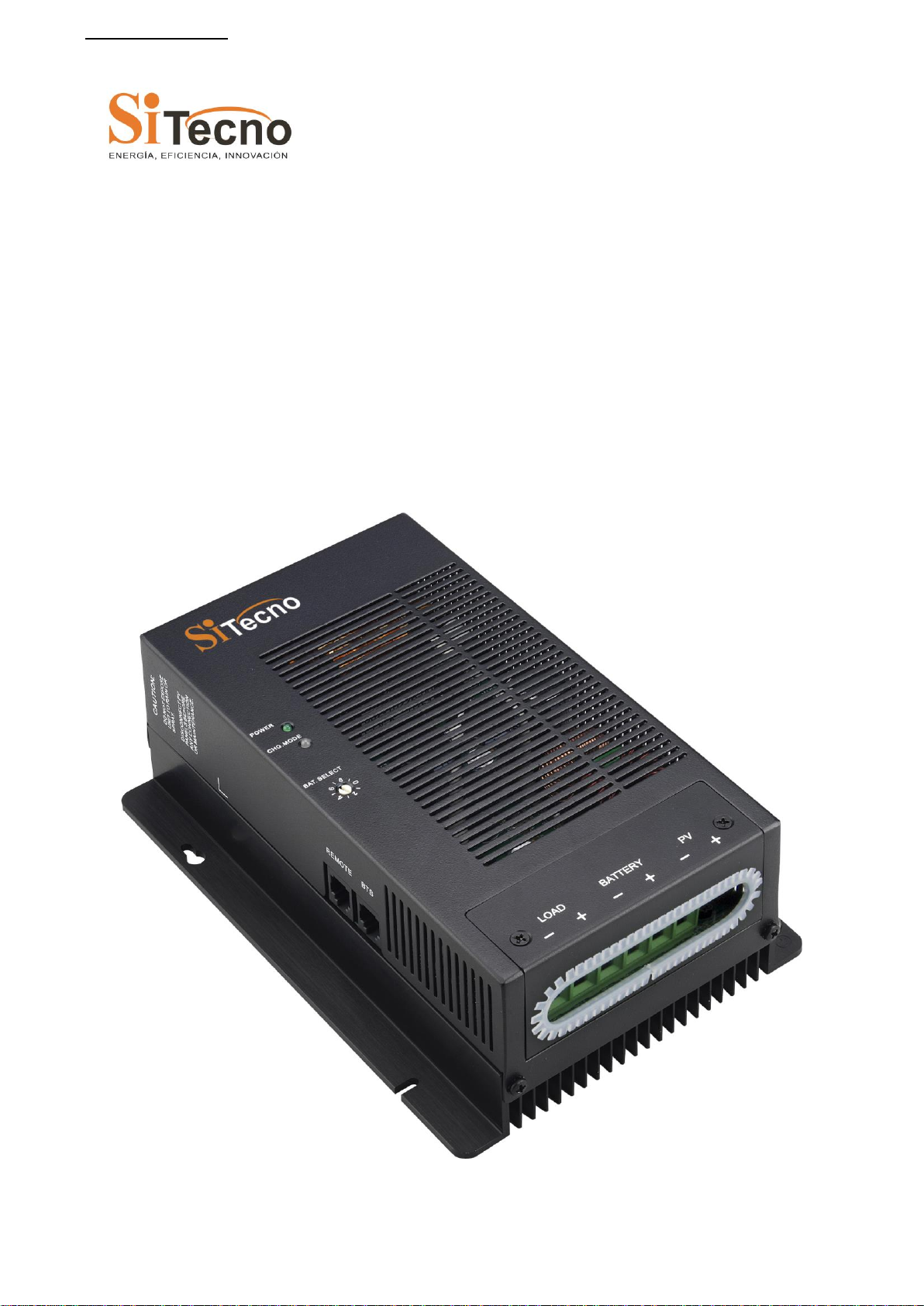
EQX 500-DC Solar Charger
User’s Manual

MATRIX Inverter System User Manual
- 2 -
Contents
Important safety instructions................................................................................................................................. 6
1. Product description ............................................................................................................................................. 8
1.1 General description...................................................................................................................................... 8
1.2 Features........................................................................................................................................................ 8
1.3 Maximum setpoint voltage limit.................................................................................................................. 8
1.4 Temperature and output power.................................................................................................................... 8
1.5 Maximum power point tracking (MPPT) .................................................................................................... 9
1.6 How MPPT works....................................................................................................................................... 9
1.7 Over voltage / reverse polarity protection ................................................................................................... 9
1.8 Electrostatic handling precautions............................................................................................................... 9
1.9 EQX 500-DC solar charger setup.............................................................................................................. 10
1.9.1 Factory default settings................................................................................................................... 10
1.10 Three stage charge control....................................................................................................................... 10
1.10.1 Bulk charge................................................................................................................................... 10
1.10.2Absorption charge......................................................................................................................... 10
1.10.3 Float charge................................................................................................................................... 10
1.11 Battery temperature sensor (BTS) ........................................................................................................... 11
1.12 Equalization charge ................................................................................................................................. 11
1.12.1 Photovoltaic charge and load controller.........................................................................................11
1.12.2Automatic PV array night disconnect........................................................................................... 12
1.12.3 EQX 500-DC solar chargerload control........................................................................................ 12
1.12.4 Low voltage disconnect................................................................................................................ 12
1.12.5 Low voltage reconnect.................................................................................................................. 12
1.13 Optional accessories ................................................................................................................................ 13
2. Installation.......................................................................................................................................................... 14
2.1 Pre-Installation........................................................................................................................................... 14
2.2 Removing the topcover.............................................................................................................................. 14
2.3 Mounting the EQX 500-DC solar chargercontroller.................................................................................. 15
2.3.1 Mount the EQX 500-DC solar charger charge controller............................................................... 15
2.4 Configuring the EQX 500-DC solar charger charge controller................................................................. 16
2.4.1 Battery type selector can apply different charger method............................................................... 16
2.5 Temperature compensation........................................................................................................................ 17
2.5.1 Temperature compensation based on battery type.......................................................................... 18
2.5.2Automatic battery temperature compensation................................................................................. 18
2.6 Grounding.................................................................................................................................................. 19
2.7 DC terminal connector locations ............................................................................................................... 19
2.8 Wire Size and Over-current Protection Requirements............................................................................... 19
2.8.1 Current Rating ................................................................................................................................ 19
2.8.2 Surge Protection.............................................................................................................................. 20
2.8.3 Over-current Protection .................................................................................................................. 20
2.8.4 Long-distance wire runs.................................................................................................................. 20
2.9 PV Charge And Load Control Mode Wiring............................................................................................. 20
2.10 Easily install in parallel connection......................................................................................................... 22
2.11 Battery type selector................................................................................................................................ 22
2.12 Installing Optional Accessories............................................................................................................... 23
2.13 Reinstalling the Faceplate........................................................................................................................ 23
3. Operation............................................................................................................................................................ 25
3.1 Basic Operation ......................................................................................................................................... 25
3.2 LED Status Indicator ................................................................................................................................. 25
3.2.1 Charge control indications.............................................................................................................. 25
4. Troubleshooting................................................................................................................................................. 27
5. Specifications...................................................................................................................................................... 28
5.1 Specifications............................................................................................................................................. 28
5.2 Environmental............................................................................................................................................ 28
5.2.1 Temperature.................................................................................................................................... 28
5.3 Safety......................................................................................................................................................... 29
5.3.1American market............................................................................................................................. 29
5.3.2 European market............................................................................................................................. 29

MATRIX Inverter System User Manual
- 3 -
5.4 Humidity.................................................................................................................................................... 29
5.4.1 Operating Humidity........................................................................................................................ 29
5.4.2 Non-Operating Humidity................................................................................................................ 29
5.5 Mechanical features................................................................................................................................... 29
5.6 Detailed dimension drawing...................................................................................................................... 30
6. Batteries.............................................................................................................................................................. 31
6.1 Battery Types............................................................................................................................................. 31
6.2 Automotive Batteries................................................................................................................................. 31
6.3 Maintenance-Free Batteries....................................................................................................................... 31
6.4 Deep-Cycle Batteries................................................................................................................................. 31
6.5 Sealed Batteries ......................................................................................................................................... 31
6.6 NiCad and NiFe Batteries.......................................................................................................................... 31
6.7 Battery Sizing ............................................................................................................................................ 31
6.8 Equalization Charging............................................................................................................................... 32
6.9 Equalization Setpoints (Non-Sealed Batteries Only)................................................................................. 32

MATRIX Inverter System User Manual
- 4 -
Tables
Table 1 –1: Factory shipping settings ............................................................................................................. 10
Table 1 –2: Battery type selector switch settings............................................................................................ 16
Table 1 –3: Temperature compensation calculation........................................................................................ 18
Table 1 –4: Battery compensation coefficient................................................................................................. 18
Table 1 –5: Minimum wire size...................................................................................................................... 20
Table 1 –6: The LED indicators...................................................................................................................... 26
Table 1 –7: Troubleshooting list ..................................................................................................................... 27
Table 1 –8: Electrical specification................................................................................................................. 28
Table 1 –9: Mechanical specification ............................................................................................................. 29
Table 1 –10: Battery equalization................................................................................................................... 32
Figures
Figure 1 –1: Bulk charge curve....................................................................................................................... 10
Figure 1 –2: PV charge and load controller.................................................................................................... 12
Figure 1 –3: Load controller........................................................................................................................... 12
Figure 1 –4: Removing the topcover .............................................................................................................. 14
Figure 1 –5: Mounting the EQX 500-DC solar charger charge controller...................................................... 15
Figure 1 –6: Battery type selector (B.SEL) .................................................................................................... 16
Figure 1 –7: Safety (Earth) ground................................................................................................................. 19
Figure 1 –8: DC terminal connector locations................................................................................................ 19
Figure 1 –9: PV charge control mode wiring.................................................................................................. 21
Figure 1 –10: Parallel connection................................................................................................................... 22
Figure 1 –11: battery type selector.................................................................................................................. 22
Figure 1 –12: Install BTS ............................................................................................................................... 23
Figure 1 –13: Reinstalling the faceplate......................................................................................................... 24
Figure 1 –14: LED status indicator................................................................................................................. 25
Figure 1 –15: EQX 500-DC solar charger dimension drawing....................................................................... 30

MATRIX Inverter System User Manual
- 5 -
About This Manual
Purpose
The purpose of this manual is to provide explanations and procedures for installing, operating, maintaining, and
troubleshooting the Solar Charge Controller.
Scope
This manual provides safety guidelines, detailed planning and setup information, procedures for installing the
Solar Charge Controller, as well as information about operating and troubleshooting the unit. It does not provide
details about particular brands of batteries. You need to consult individual battery manufacturers for this
information.
Audience
This manual is intended for anyone who needs to install and operate the Solar Charge Controller. Installers should
be certified technicians or electricians.
Organization
This Manual is organized into six chapters.
Chapter 1. Product description
Chapter 2. Installation
Chapter 3. Operation
Chapter 4. Troubleshooting
Chapter 5. Specification
Chapter 6. Battery

MATRIX Inverter System User Manual
- 6 -
I
Im
mp
po
or
rt
ta
an
nt
t
s
sa
af
fe
et
ty
y
i
in
ns
st
tr
ru
uc
ct
ti
io
on
ns
s
Save these instructions
This manual contains important instructions for EQX 500-DC solar charger that shall be followed during
installation and maintenance.
General
1. Refer installation and servicing to qualified service personnel. High voltage is present inside unit. Incorrect
installation or use may result in risk of electric shock or fire. No user serviceable parts in this unit.
2. Remove all sources of power, photovoltaic and battery before servicing or installing.
3. Warning –risk of explosive gases
When EQX 500-DC solar charger is working, Please DO NOT touch it because the temperature is
too high.
Working in the vicinity of lead-acid batteries is dangerous. Batteries produce explosive gasses
during normal battery operation.
To reduce risk of battery explosion, follow these instructions and those published by battery
manufacturer and manufacturer of any equipment you intend to use in vicinity of battery.
4. Personal precautions
Someone should be within range of your voice or close enough to come to your aid when you work
near a lead-acid battery.
Have plenty of fresh water and soap nearby in case battery acid contacts skin, clothing or eyes.
Wear complete eye protection and clothing protection.Avoid touching eyes while working near
battery.
If battery acid contacts skin or clothing, wash immediately with soap and water. If acid enters eye,
immediately flood eye with running cold water for at least 10 minutes and get medical attention
immediately.
NEVER smoke or allow a spark or flame in vicinity of battery.
Be extra cautious to reduce risk of dropping metal tool onto battery. It might spark or short circuit
battery or other electrical part that may cause explosion.
Remove personal metal items such as rings, bracelets, necklaces, and watches when working with a
lead-acid battery. A lead-acid battery can produce a short circuit current high enough to weld a ring
or the like to metal, causing a severe burn.
5. Preparing to charge
Never charge a frozen battery.
Be sure battery is mounted in a well-ventilated compartment.
Add distilled water in each cell until battery acid reaches level specified by battery manufacturer.
This helps purge excessive gas from the cells. Do not overfill. For a battery without cell caps,
carefully follow manufacturers charging instructions.
6. Charger location & installation
Controller employs components that tend to produce arcs or sparks. NEVER install in battery
compartment or in the presence of explosive gases.
Protect all wiring from physical damage, vibration and excessive heat.
Insure that the controller is properly setup for the battery being charged.
Do not expose the controller to rain or snow.
Insure all terminating connections are clean and tight to prevent arcing and overheating.
Charging system must be properly installed as described in these instructions prior to operation.
Do not connect to a PV array capable of producing greater than 40 amps of short circuit current @
25°C.
Do not connect input to DC source directly with load, EQX 500-DC solar charger need to .be
powered by solar panel.
MATRIX Inverter System User Manual
- 7 -
Symbol
--Warning
--Dangerous Voltage
--Alternative Current
--Direct Current
--Protective Earth
--ESD
Abbreviations and Acronyms
BTS
Battery Temperature Sensor
DC
Direct Current
LED
Light Emitting Diode
LVD
Low Voltage Disconnect
LVR
Low Voltage Reconnect
B.SEL
Battery type selector
CHG.MODE
Charge mode
PV
Photovoltaic
MPPT
Maximum Power Point Tracking
PWM
Pulse Width Modulation
RE
Renewable Energy

MATRIX Inverter System User Manual
- 8 -
1
1.
.
P
Pr
ro
od
du
uc
ct
t
d
de
es
sc
cr
ri
ip
pt
ti
io
on
n
1
1.
.1
1
G
Ge
en
ne
er
ra
al
l
d
de
es
sc
cr
ri
ip
pt
ti
io
on
n
EQX 500-DC solar charger is a 40 amp 12/24 voltage Maximum Power Point Tracking (MPPT) photovoltaic (PV)
battery charge controller. Through the use of MPPT technology, EQX 500-DC solar charger can increase charge
current up to 30% or more compared to conventional controllers. Solar Charge Controller’s sophisticated three
stage charge control system can be configured to optimize charge parameters to precise battery requirements. The
unit is fully protected against voltage transients, over temperature, over current, reverse battery and reverse PV
connections. An automatic current limit feature allows use of the full 40 amp capability without worrying about
overload or nuisance fuse blow from excessive current, voltage or amp-hour based load control.
Series pass Pulse Width Modulation (PWM) charge voltage control combined with a multistage charge control
algorithm leads to superior charging and enhanced battery performance. The filtered PWM power control system
uses highly efficient and reliable power MOSFET transistors. The MOSFET’s are turned on and off at high
frequency to precisely control charge voltage and MPPT.
Fully automatic temperature compensation of charge voltage is available to further improve charge control and
battery performance. The optional battery temperature sensor is built for long term reliability. The sensor element
is environmentally sealed and encapsulated into a plastic lug which adheres to directly to the battery terminal and
by RJ11 port connect with the unit, and the EQX 500-DC solar charger also includes an isolated RS232 port for
connection to a PC computer for data logging and system monitoring.
The EQX 500-DC solar charger can easily install in parallel connection, so it also suitable for large system current
application condition.
1
1.
.2
2
F
Fe
ea
at
tu
ur
re
es
s
High converting efficiency up to 97% for minimizing energy loss
Build-in MPPT tracker for optimizing the power transformation
Reversed current protection with fuse
Automatic battery temperature compensation for long-term reliability
Capable of selecting different charging mode for various type of batteries
Capable of connecting additional DC load for wider applications
Three stage charge control system (bulk, absorption, and float mode) with temperature
compensation
LED indicators display charge status in real time
Pulse Width Modulation (PWM) topology combined with a multi-stage charge control
algorithm leads to superior charging and enhanced battery performance
1
1.
.3
3
M
Ma
ax
xi
im
mu
um
m
s
se
et
tp
po
oi
in
nt
t
v
vo
ol
lt
ta
ag
ge
e
l
li
im
mi
it
t
Very cold batteries combined with high charge voltage setpoints can produce voltages high enough to disrupt or
damage other equipment connected to the battery. To minimize possible damage a maximum voltage setpoint limit
feature is provided. The factory defaults can be adjustable using software. Regardless of what setpoint values
result from temperature compensation, the EQX 500-DC solar charger will never attempt to apply a charge
voltage greater than the maximum voltage setpoint limit value.
1
1.
.4
4
T
Te
em
mp
pe
er
ra
at
tu
ur
re
e
a
an
nd
d
o
ou
ut
tp
pu
ut
t
p
po
ow
we
er
r
Over temperature protection is provided to protect the unit from damage due to high output power at high ambient
temperatures. When mounted vertically as described in the installation section, the unit can deliver full output in a
temperature of up to 40ºC, and the unit will de-rate output in 40 –60ºC. While operating in charge mode, the
controller will decrease the charge current to reduce the transistor temperature and the green led will be solid
green. If the EQX 500-DC solar charger connected with DC load, the load is disconnected before the transistors
reach an excessive temperature and the green LED flashes. Once the temperature has dropped, the loads are
reconnected., reducing average power delivery to within safe limits. During thermal shutdown the charge status
indicator will display an “off” condition. Over temperature shutdown occurs when the ambient temperature
reaches 60ºC.

MATRIX Inverter System User Manual
- 9 -
1
1.
.5
5
M
Ma
ax
xi
im
mu
um
m
p
po
ow
we
er
r
p
po
oi
in
nt
t
t
tr
ra
ac
ck
ki
in
ng
g
(
(M
MP
PP
PT
T)
)
MPPT and associated current boost operation is fully automatic and will function whenever sufficient PV voltage
and current are available. The percent increase in output charge current relative to PV current is variable, and will
change with operating conditions. When conditions are such that insufficient PV power is available to produce an
increase in output current, the unit will stop it’s internal DC-DC power conversion and operate as a series pass
PWM controller with very low forward voltage drop.
The principal operating conditions which affect current boost performance are PV array temperature and battery
voltage. At constant solar intensity available PV power changes with PV temperature. A PV array’s power vs.
temperature characteristic is such that a cool PV array can produce a higher voltage and more power, than a hot
PV array. When PV voltage is sufficiently high for MPPT to operate, a constant power output is delivered to the
battery. Since output power is constant while MPPT is operating, a decrease in battery voltage produces
corresponding increase in charge current. This means that the greatest current increase occurs with a combination
of cool ambient temperature and low battery voltage. The unit delivers the greatest charge current increase when
you need it most, in cold weather with a discharged battery. Additionally, anything that can be done to lower PV
array temperature will also lead to increased charge current by increasing PV power production. In
cool/comfortable temperatures and typical battery states of charge, most systems see about 10 –20% increase.
Charge current increase can go to zero in hot temperatures, whereas charge current increase can easily exceed
30% with a discharged battery and freezing temperatures.
1
1.
.6
6
H
Ho
ow
w
M
MP
PP
PT
T
w
wo
or
rk
ks
s
A PV module is a constant current type device. As shown on a typical PV module voltage vs. current curve,
current remains relatively constant over a wide range of voltage. A typical 75 watt module is specified to deliver
4.45 amps @ 17 volts @ 25 C cell temperature. Conventional PV controllers essentially connect the PV array
directly to the battery when battery is discharged. When a 75 watt module is connected directly to a battery
charging at 12 volts, the module still provides approximately the same current. But, because output voltage is now
at 12 volts rather than 17 volts, module power production is artificially limited and the 75W module only delivers
53 watts. This wastes 22 watts of available power.
Solar Charge Controller’s MPPT technology operates in a very different fashion. Under these conditions EQX
500-DC solar charger calculates the maximum power voltage (V) at which the PV module delivers maximum
power, in this case 17 volts. It then MPPT operates the module 17 volts which extracts maximum available power
from the module. EQX 500-DC solar charger continually recalculates the maximum power voltage as operating
conditions change. Input power from the maximum power tracking controller, in this case 75 watts, feeds a
switching type power converter which reduces the 17 volt input to battery voltage at the output. The full 75 watts
which is now being delivered at 12 volts would produce a current of 6.25 amps. A charge current increase of 1.8
amps or 40% is achieved by converting the 22 watts that would have been wasted into useable charge current.
Note that this example assumes 100% efficiency to illustrate the principal of operation. In actual operation, boost
will be somewhat less.
1
1.
.7
7
O
Ov
ve
er
r
v
vo
ol
lt
ta
ag
ge
e
/
/
r
re
ev
ve
er
rs
se
e
p
po
ol
la
ar
ri
it
ty
y
p
pr
ro
ot
te
ec
ct
ti
io
on
n
EQX 500-DC solar charger is fully protected against reverse polarity and high voltage transients for both the PV
and the battery connections. If the battery is connected reverse polarity, EQX 500-DC solar charger will not
operate. If the PV array is connected reverse polarity the charge control system will not turn on.
1
1.
.8
8
E
El
le
ec
ct
tr
ro
os
st
ta
at
ti
ic
c
h
ha
an
nd
dl
li
in
ng
g
p
pr
re
ec
ca
au
ut
ti
io
on
ns
s
All electronic circuits may be damaged by static electricity. To minimize the likelihood of electrostatic damage,
discharge yourself by touching a water faucet or other electrical ground prior to handling the unit and avoid
touching components on the circuit boards. The risk of electrostatic damage is highest when relative humidity is
below 40%.
MATRIX Inverter System User Manual
- 10 -
1
1.
.9
9
E
EQ
QX
X
5
50
00
0-
-D
DC
C
s
so
ol
la
ar
r
c
ch
ha
ar
rg
ge
er
r
s
se
et
tu
up
p
1.9.1 Factory default settings
Table 1 –1: Factory shipping settings
Basic settings
Charge mode
3 stage
Absorption voltage
14.4/28.8V
Bulk voltage
14.6/29.2V
Float voltage
13.4/26.8V
Equalize
14/28V
1
1.
.1
10
0
T
Th
hr
re
ee
e
s
st
ta
ag
ge
e
c
ch
ha
ar
rg
ge
e
c
co
on
nt
tr
ro
ol
l
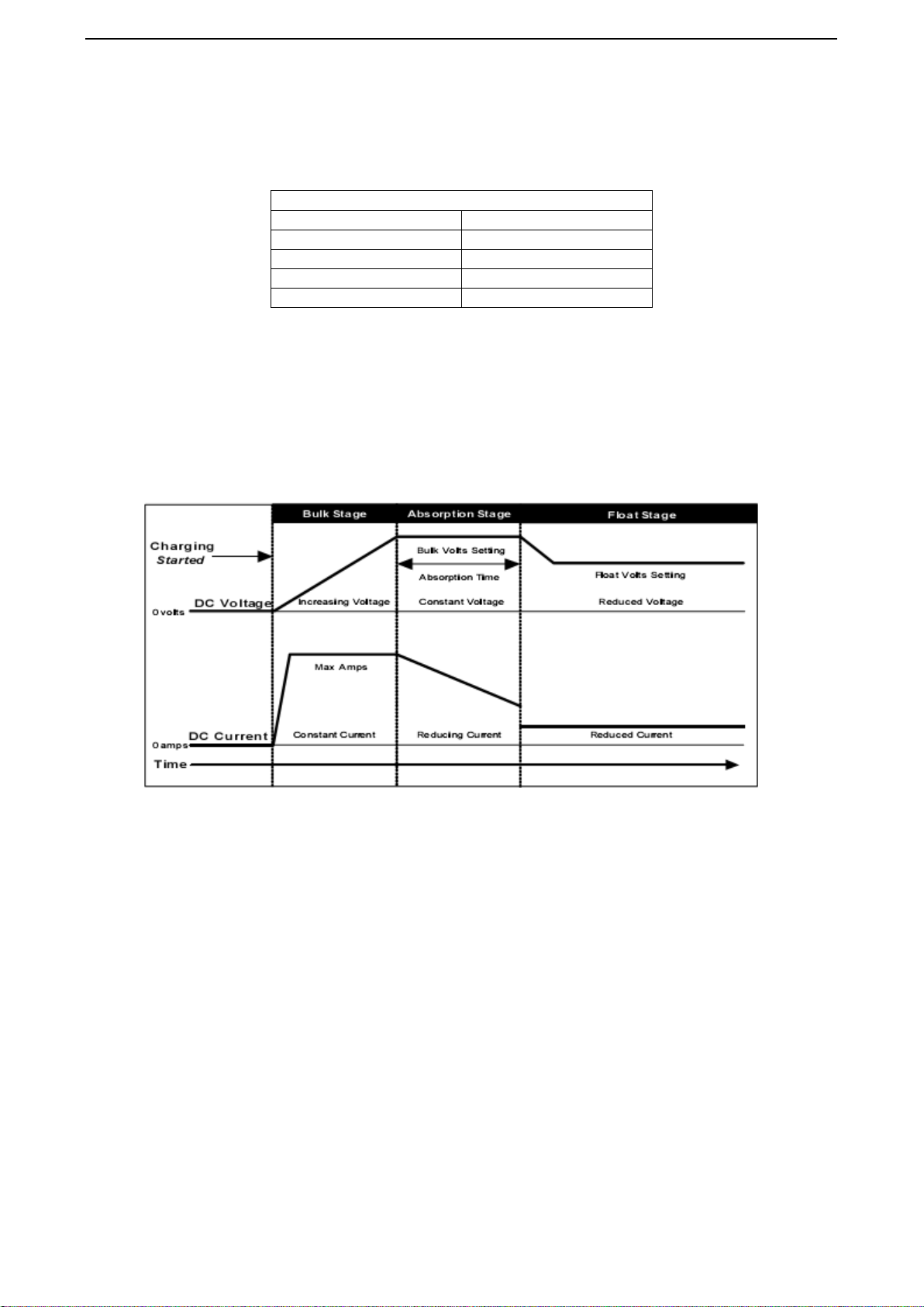
EQX 500-DC solar charger is typically configured for a three stage charging process, Bulk, Absorption and Float.
The three stage charge process provides a somewhat higher charge voltage to charge the battery quickly and safely.
Once the battery is fully charged a somewhat lower voltage is applied maintain the battery in a fully charged state
without excessive water loss. The three stage charge process charges the battery as quickly as possible while
minimizing battery water loss and maintenance.
Figure 1 –1: Bulk charge curve
1.10.1 Bulk charge
When charge starts the EQX 500-DC solar charger attempts to apply the bulk charge voltage to the
battery. The system will switch to Bulk charge if the battery is sufficiently discharged and/or insufficient
charge current is available to drive the battery up to the bulk voltage setpoint. During the Bulk charge
stage the unit delivers as much charge current as possible to rapidly recharge the battery. Once the charge
control system enters Absorption or Float, the unit will again switch to Bulk charge if battery voltage
drops below the present charge voltage setpoint.
1.10.2Absorption charge
During this stage, the unit changes to a constant voltage mode where the absorption voltage is applied
to the battery. When charge current decreases to the float transition current setting, the battery is fully
charged and the unit switches to the float stage.
1.10.3 Float charge
During this stage, the float voltage is applied to the battery to maintain it in a fully charged state.
When battery voltage drops below the float setting for a cumulative period, a new bulk cycle will be
triggered.

MATRIX Inverter System User Manual
- 11 -
1
1.
.1
11
1
B
Ba
at
tt
te
er
ry
y
t
te
em
mp
pe
er
ra
at
tu
ur
re
e
s
se
en
ns
so
or
r
(
(B
BT
TS
S)
)
The charge voltage required by batteries changes with battery temperature. Temperature compensation of charge
voltage enhances battery performance and life, and decreases battery maintenance. Automatic temperature
compensation can be provided through use of the optional battery temperature sensor. The following table
describes approximately how much the voltage may vary depending on the temperature of the batteries.
1
1.
.1
12
2
E
Eq
qu
ua
al
li
iz
za
at
ti
io
on
n
c
ch
ha
ar
rg
ge
e
Equalize charging is a special mode of battery charging. During use, the battery’s cells can become unequal in the
voltage and current they can deliver. This is due to a buildup of sulfate on the plates as well as stratified
electrolyte. Sulfate prevents the cells from receiving or delivering full power. If the sulfate is left on the plates, it
will harden, and permanently reduce the battery’s capacity. Stratification separates the heaver acid from the water,
and the concentrated acid remains at the lower portion of the plates, eventually corroding them. Equalizing the
batteries every month or two (depending on usage) prolongs the life of the batteries and provides better battery
performance.
To set the Equalize Charge:
Remove all DC loads connected to the batteries.
Remove all battery vent caps.
Check the battery water level, it should be just over the top of the plates (do not over fill). Use only
distilled water for filling batteries.
Set the BATTERY TYPE SELECTOR switch to position “0” or “1”.
Reset the BATTERY TYPE SELECTOR potentiometer to the appropriate setting for the system
batteries when the Equalize charge has completed.
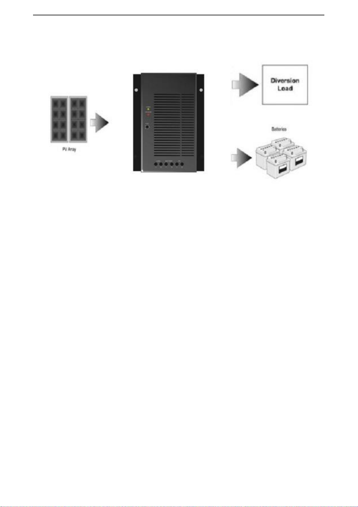
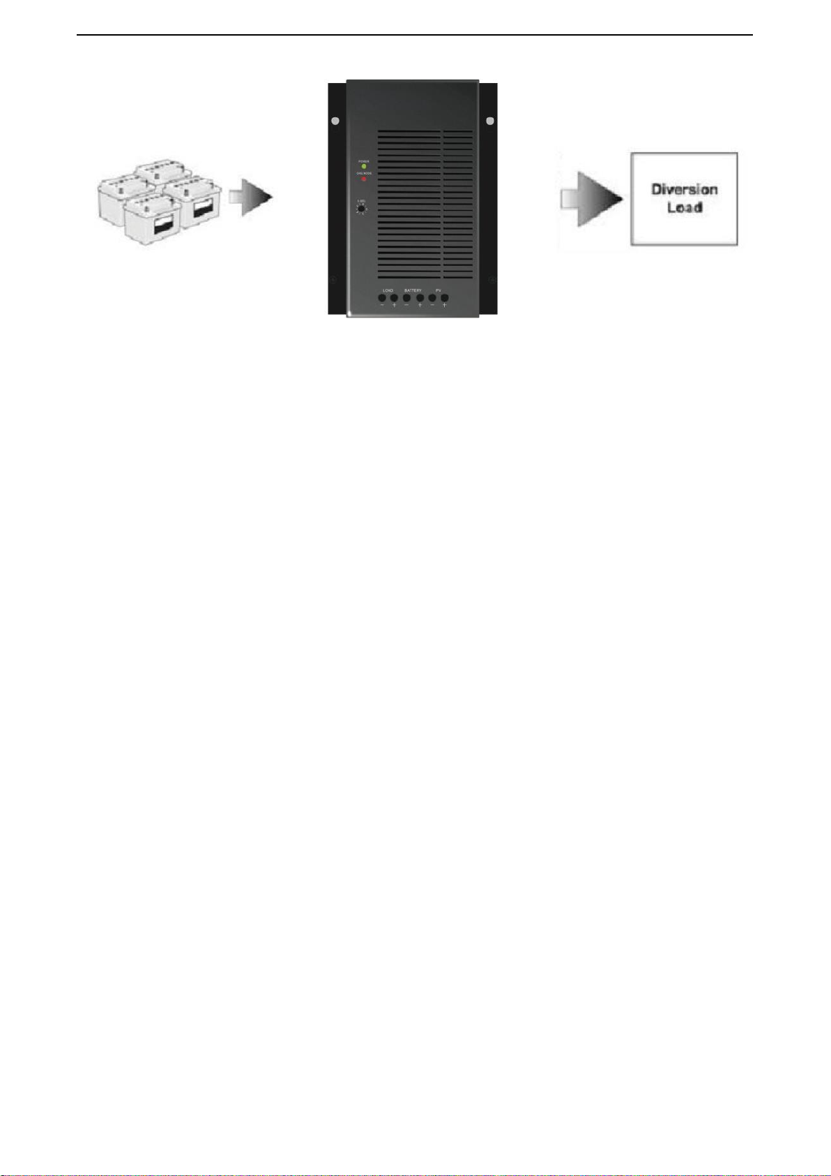
1.12.1 Photovoltaic charge and load controller
The EQX 500-DC solar charger charge controller can operate as a PV charge controller. the controller can
regulate up to 40amps of continuous photovoltaic (PV) array current at 12 / 24-volts DC for charging batteries.
This rating includes the NEC required derating. But at the same time the EQX 500-DC solar charger charge
controller can provide the maximum 15Amp current to DC load , however the rating charge current 40Amp will
decrease. That is to say, the rating 40Amp current is shared battery with DC load.
When the PV voltage is lower, the battery will provide the power to the DC load , In the load control condition,
the EQX 500-DC solar charger controls when to remove load from the system when an over-discharge or
over-load situation occurs. The EQX 500-DC solar charger charge controller uses the software setpoints to
determine when to connect or reconnect loads depending on battery voltage. EQX 500-DC solar charger prevents
damage to the battery from over-discharge during periods of poor weather or excessive loads. The unit can charge
the batteries when in this function.
If the PV array’s output increases above the rated amp level, the controller will continue to operate because of
input current limit
MATRIX Inverter System User Manual
- 12 -
Figure 1 –2: PV charge and load controller
1.12.2 Automatic PV array night disconnect
When using PV Charge Control mode, the PV array is automatically disconnected from the battery at night to
prevent reverse leakage of power.
1.12.3 EQX 500-DC solar charger load control
The EQX 500-DC solar charger charge controller can operate as a low voltage disconnect (LVD) for DC loads to
prevent over-discharge to batteries during periods of poor charging or excessive loads. The EQX 500-DC solar
charger charge controller uses the software setpoints to determine when to disconnect or reconnect loads
depending on battery voltage.
1.12.4 Low voltage disconnect
When configured as a load controller, the EQX 500-DC solar charger charge controller will disconnect the load
from the batteries when it reaches the LVD setting. There will be a 1-minute delay after the voltage drops below
the Low Voltage Disconnect (LVD) setting before the controller actually disconnects the load.
1.12.5 Low voltage reconnect
It can also provide automatic reconnection of the loads at the low voltage reconnect (LVR) setting. Reconnection
of the load is allowed once the battery voltage has exceeded the low voltage reconnect (LVR) setting. Loads are
either automatically when battery voltage exceeds the low voltage reconnect (LVR) setting for 1 minutes.
Figure 1 –3: Load controller
MATRIX Inverter System User Manual
- 13 -
Important: When using the EQX 500-DC solar charger load control:
Do not temperature-compensate these settings.
Do not install the optional battery temperature compensation sensor.
1
1.
.1
13
3
O
Op
pt
ti
io
on
na
al
l
a
ac
cc
ce
es
ss
so
or
ri
ie
es
s
The follow accessories can be purchased for use with the EQX 500-DC solar charger charge Multifunction DC
Controller:
Battery Temperature Sensor (BTS): The BTS is installed on the side of the battery and attaches to RS232 port
inside the EQX 500-DC solar charger charge controller. It provides accurate sensing of the battery temperature
and uses this reading to control charging. Using this accessory can extend battery life and improve overall
charging.
MATRIX Inverter System User Manual
- 14 -
2
2.
.
I
In
ns
st
ta
al
ll
la
at
ti
io
on
n
2
2.
.1
1
P
Pr
re
e-
-I
In
ns
st
ta
al
ll
la
at
ti
io
on
n
The instructions that follow are applicable to the typical installation. For special applications, consult a qualified
electrician or your Certified Dealer. Installation procedures will vary according to your specific application.
Important: Installations should meet all local codes and standards. Installations of this equipment should only
be performed by skilled personnel such as qualified electricians and Certified Renewable Energy (RE)
System Installers.
2
2.
.2
2
R
Re
em
mo
ov
vi
in
ng
g
t
th
he
e
t
to
op
pc
co
ov
ve
er
r
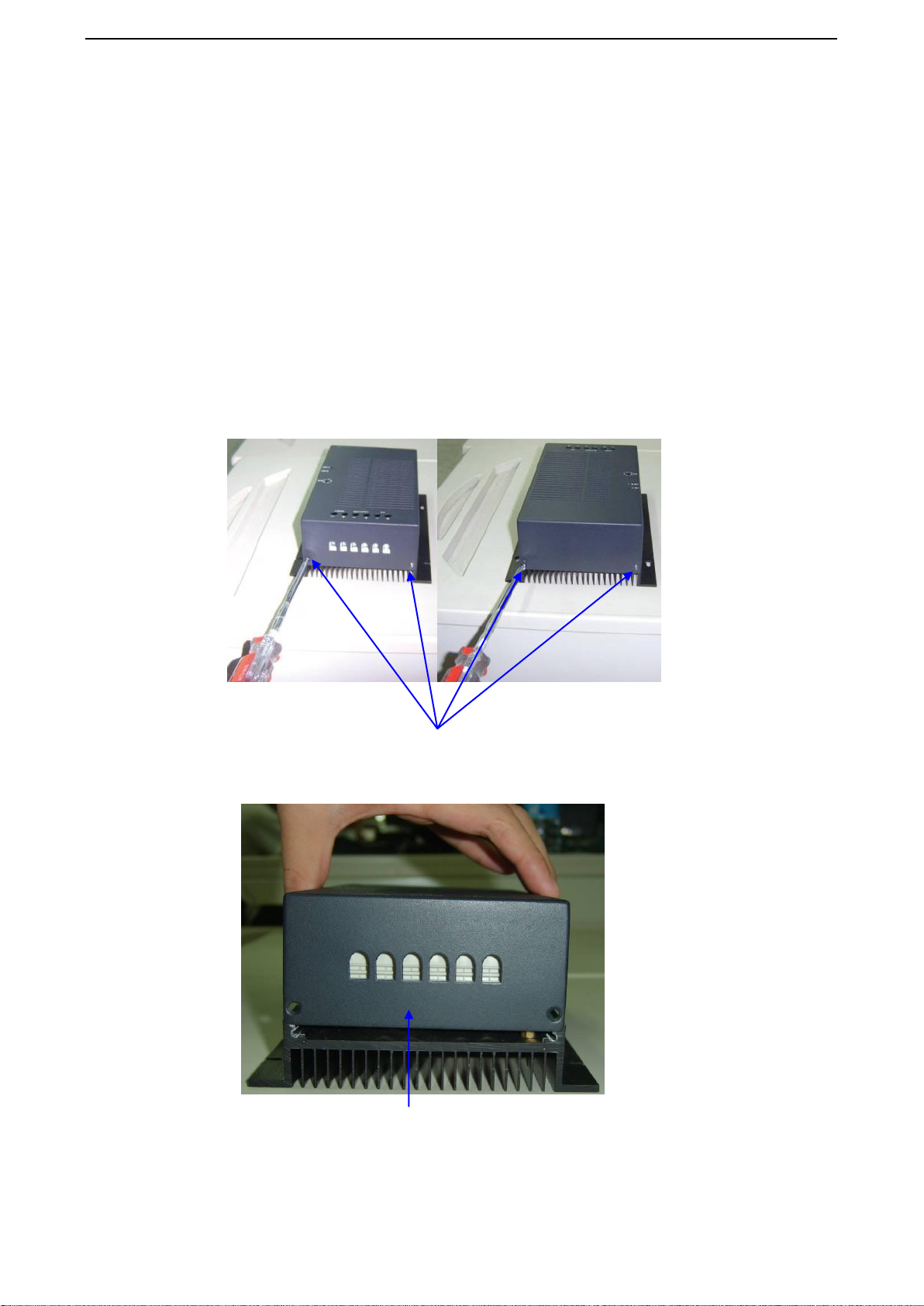
1. Access the inside of the controller by removing the four screws M3*6 on the cover of the unit.
2. Remove the topcover of EQX 500-DC solar charger charge controller.
Figure 1 –4: Removing the topcover
Remove these screws M3*6 (*4) from the topcover to access the heatsink of controller
Remove the topcover
MATRIX Inverter System User Manual
- 15 -
2
2.
.3
3
M
Mo
ou
un
nt
ti
in
ng
g
t
th
he
e
E
EQ
QX
X
5
50
00
0-
-D
DC
C
s
so
ol
la
ar
r
c
ch
ha
ar
rg
ge
er
r
c
co
on
nt
tr
ro
ol
ll
le
er
r
The EQX 500-DC solar charger charge controller is designed for indoor mounting. Care should be taken in
selecting a location and when mounting the enclosure. Avoid mounting it in direct sunlight to prevent heating of
the enclosure. The enclosure should be mounted vertically on a wall. In outdoor installations, the EQX 500-DC
solar charger charge controller must be installed in a rainproof enclosure to eliminate exposure to rain, mist or
water-spray.
Caution: Damage to EQX 500-DC solar charger charge Controller, Install the EQX 500-DC solar charger
charge controller in a dry, protected location away from sources of high temperature, moisture, and vibration.
Exposure to saltwater is particularly destructive. Corrosion is not covered by the warranty.
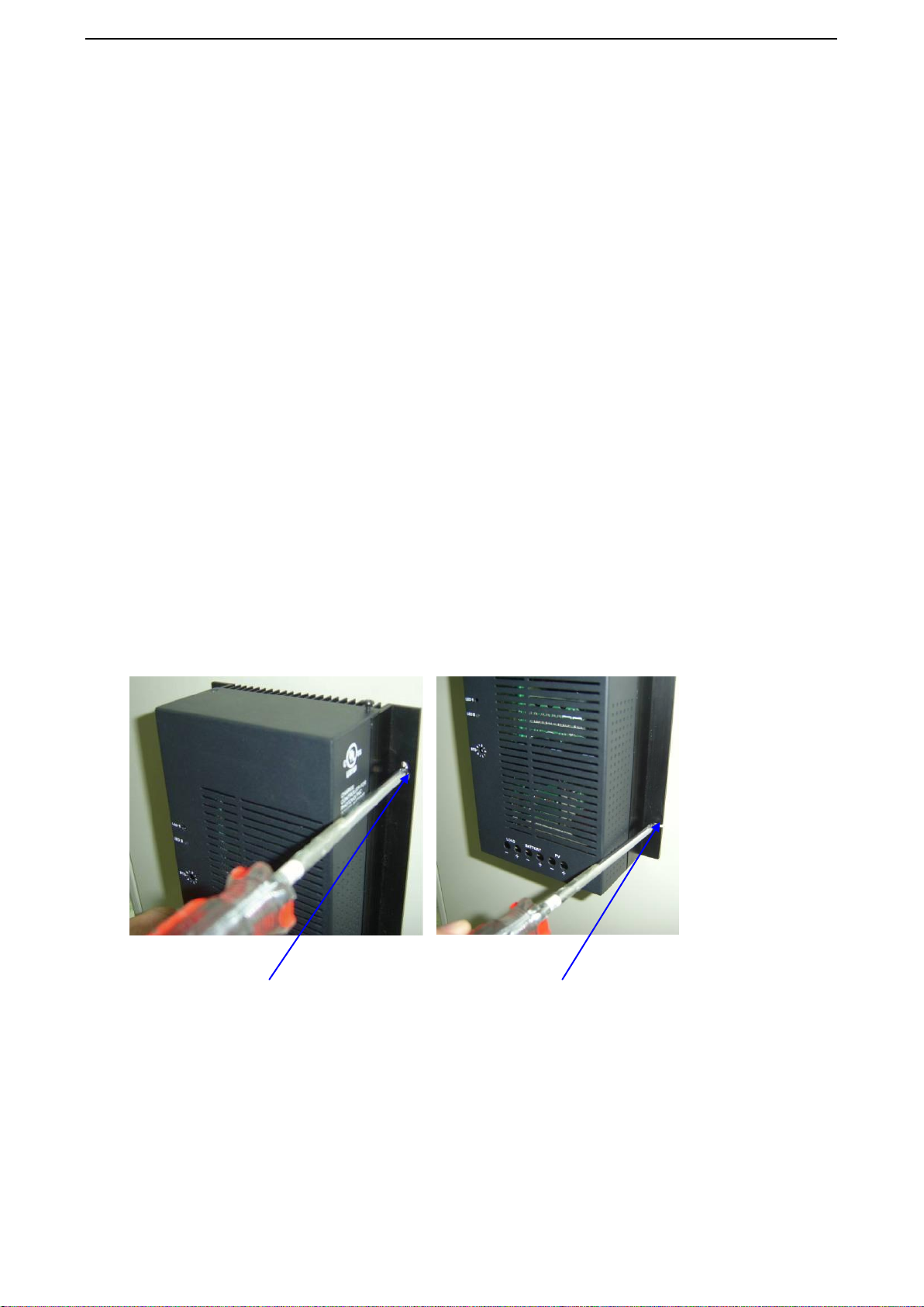
2.3.1 Mount the EQX 500-DC solar charger charge controller
1. Place the controller on the desired mounting surface and mark the location of the keyhole slots on the wall.
2. Move the controller out of the way, and secure two mounting screws in the locations marked. Leave the screw
heads backed out approximately 1/4inch (6 mm) or less.
3. Place the controller onto the screws and pull it down into the keyhole slots.
4.Then insert the two screws provided to secure the enclosure onto the wall.
Warning: Explosion/Corrosion Hazard
Do not locate the EQX 500-DC solar charger charge controller in a sealed compartment with the batteries.
Batteries can vent hydrogen-sulfide gas, which is corrosive to electronic equipment. Batteries also generate
hydrogen and oxygen gas that can explode when exposed to a spark.
Figure 1 –5: Mounting the EQX 500-DC solar charger charge controller
Keyhole Slots (*2) for mounting
Additional Mounting Holes (*2)
MATRIX Inverter System User Manual
- 16 -
2
2.
.4
4
C
Co
on
nf
fi
ig
gu
ur
ri
in
ng
g
t
th
he
e
E
EQ
QX
X
5
50
00
0-
-D
DC
C
s
so
ol
la
ar
r
c
ch
ha
ar
rg
ge
er
r
c
ch
ha
ar
rg
ge
e
c
co
on
nt
tr
ro
ol
ll
le
er
r
Before making any wiring connections to the EQX 500-DC solar charger charge controller, it must be configured
for the desired mode of operation. The following sections describe the how to configure the unit for the desired
application and function.
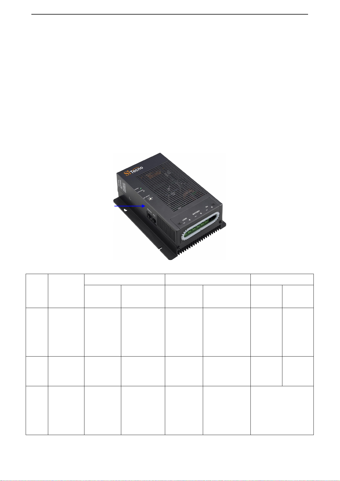
2.4.1 Battery type selector can apply different charger method
The battery type selector is a 10 position rotary switch used to set the EQX 500-DC solar charger for the proper
float and bulk voltage levels. These levels are selected depending on the type of batteries used. Refer to the table
below for the charge voltages in the various switch positions. Consult the battery manufacturer for optimum
battery voltage charging settings.
Figure 1 –6: Battery type selector (B.SEL)
Table 1 –2: Battery type selector switch settings
Switch
Position
Description
12-volt
24-volt
Charge Function
Float voltage
(V)
Bulk/ Equalize
voltage (V)
Float voltage
(V)
Bulk/ Equalize
voltage (V)
Equalize
charge rate
Equalize
time
0
Equalize 1 -
equalizes at a
rate equal to
the battery
bank capacity
(in amp hours)
divided by 40.
13.2
*15
26.4
*30
Max 40Amp
Depend on
battery
capacity
1
Equalize 2
–depend on
customer
reset .
reserved
reserved
reserved
reserved
2
Deep Cell
Lead Acid 2
13.3
15
26.6
30
Provides an additional
Float and Bulk settings
for deep cycle, lead acid
batteries. Refer to the
battery manufacturer
recommendation for
Float and Bulk settings.
B.SEL

MATRIX Inverter System User Manual
- 17 -
3
Not Specified
13.6
14.3
27.2
28.6
Provides an additional
setting of Bulk and Float
voltages.
4
Gel Cel 2
13.7
14.4
27.4
28.8
Recommended for gel
cell batteries that specify
high float voltages.
Check with the battery
manufacturer.
5
Gel Cell 1
13.5
14.1
27
28.2
Typical gel cell setting.
6
PcCa-lead
Calcium
13.2
14.3
26.4
28.6
Use this setting for sealed
type car batteries.
7
Deep Cycle
Lead Acid 1
(Default
Setting)
13.4
14.6
26.8
29.2
Factory setting for typical
deep cycle lead acid
batteries.
8
NiCad 1
14
16
28
32
Use for NiCad battery
systems.
9
NiCad 2
14.5
16
29
32
Recommended for use
with nickel iron batteries.
Important:
1. Switch positions “0” and “1” are for monthly battery maintenance only. Equalize voltages are displayed in the
table with an asterisk (*) –Switch positions “0” and “1” only.
2. Switch position “7” is the default values as shipped from the factory.
3. Always refer to the battery manufacturer’s specifications for equalization.
2
2.
.5
5
T
Te
em
mp
pe
er
ra
at
tu
ur
re
e
c
co
om
mp
pe
en
ns
sa
at
ti
io
on
n
For optimal battery charging, the Bulk and Float charge rates should be adjusted according to the temperature of
the battery. When battery charging voltages are compensated based on temperature, the charge voltage will vary
depending on the temperature around the batteries.

MATRIX Inverter System User Manual
- 18 -
2.5.1 Temperature compensation based on battery type
The charge voltage required by batteries changes with battery temperature. Temperature compensation of charge
voltage enhances battery performance and life, and decreases battery maintenance. Automatic temperature
compensation can be provided through use of the optional battery temperature sensor. The following table
describes approximately how much the voltage may vary depending on the temperature of the batteries.
Temperature compensation is based on battery type-5mv /cell for lead acid type batteries and 2mv/cell for alkaline
type batteries (NiCad or NiFe). The temperature compensation calculations are derived from the following table.
Table 1 –3: Temperature compensation calculation
Battery Type
12 -volt
24-volt
Lead Acid
0.03 volts (30mv) per degree Celsius
0.06 volts (60mv) per degree Celsius
NiCad
0.02 volts (20mv) per degree Celsius
0.04 volts (40mv) per degree Celsius
2.5.2Automatic battery temperature compensation
Temperature compensation can be accomplished automatically by using a Battery Temperature Sensor (BTS). The
sensor attaches directly to the side of one of the batteries in the bank and provides precise battery temperature. See
“Installing the Battery Temperature Sensor” for detailed instructions on how and where to install the BTS. If a
BTS is installed, the charge controlling process will be automatically adjusted for the battery temperature. When
using a BTS, set the Bulk and Float voltage for a battery at normal room temperature for 25 °C.
Table 1 –4: Battery compensation coefficient
Temperature
(around the BTS)
12-volt
24-volt
Celsius
Fahrenheit
Lead Acid
(6 cells)
NiCad
(10 cells)
Lead Acid
(12 cells)
NiCad
(20 cells)
60
140
-1.05
-0.7
-2.1
-1.4
55
131
-0.9
-0.6
-1.8
-1.2
50
122
-0.75
-0.5
-1.5
-1
45
113
-0.6
-0.4
-1.2
-0.8
40
104
-0.45
-0.3
-0.9
-0.6
35
95
-0.3
-0.2
-0.6
-0.4
30
86
-0.15
-0.1
-0.3
-0.2
25
77
0
0
0
0
20
68
0.15
0.1
0.3
0.2
15
59
0.3
0.2
0.6
0.4
10
50
0.45
0.3
0.9
0.6
5
41
0.6
0.4
1.2
0.8
0
32
0.75
0.5
1.5
1
-5
23
0.9
0.6
1.8
1.2
-10
14
1.05
0.7
2.1
1.4
-15
5
1.2
0.8
2.4
1.6
-20
-4
1.35
0.9
2.7
1.8
-25
-13
1.5
1
3
2
-30
-22
1.65
1.1
3.3
2.2
-35
-31
1.8
1.2
3.6
2.4
-40
-40
1.95
1.3
3.9
2.6
If using a BTS, when the battery temperature drops below 25 °C, the regulation voltage setting automatically
increases. When the temperature rises above 25 °C the regulation battery voltage setting automatically decreases.

MATRIX Inverter System User Manual
- 19 -
2
2.
.6
6
G
Gr
ro
ou
un
nd
di
in
ng
g
The EQX 500-DC solar charger charge controller is designed to work with grounded electrical systems. The metal
screw must be grounded for either system by connecting it with the heatsink. If a negative ground system is
desired, connect the negative current carrying conductor to the grounding system at one point in the system.
Consult local and national electrical codes for more information and any additional requirements.
Figure 1 –7: Safety (Earth) ground
2
2.
.7
7
D
DC
C
t
te
er
rm
mi
in
na
al
l
c
co
on
nn
ne
ec
ct
to
or
r
l
lo
oc
ca
at
ti
io
on
ns
s
Terminal connectors for DC wiring are located on the lower edge of the circuit board. Terminal Torque
Requirements. Once the wires have been installed, torque the terminals as follows. Be careful not to overtighten.
Figure 1 –8: DC terminal connector locations
2
2.
.8
8
W
Wi
ir
re
e
S
Si
iz
ze
e
a
an
nd
d
O
Ov
ve
er
r-
-c
cu
ur
rr
re
en
nt
t
P
Pr
ro
ot
te
ec
ct
ti
io
on
n
R
Re
eq
qu
ui
ir
re
em
me
en
nt
ts
s
The wiring, over-current protection devices (fuses), and installation methods used must conform to all national
and local electrical code requirements. Wiring should be protected from physical damage with conduit or a strain
relief clamp.
2.8.1 Current Rating
EQX 500-DC solar charger charge controller is rated for a rating continuous current of 40 amps. Since PV outputs
can vary due to the array size or sunlight striking it, the safe minimum wire size should be based on the maximum
current ratings.
Safety (Earth) ground
PV Negative (-)
PV Positive (+)
Battery Positive (+)
Battery Negative (-)
Load Negative (-)
Load Positive (+)

MATRIX Inverter System User Manual
- 20 -
2.8.2 Surge Protection
Since PV arrays are often mounted on an elevated structure and thus are more susceptible to lightning strikes,
protection from lightning-induced power surges and other transient power disturbances between the PV array and
the EQX 500-DC solar charger charge controller are strongly recommended. Because the EQX 500-DC solar
charger have wider input voltage range 15-55VDC.
2.8.3 Over-current Protection
If the controller detects an overload, it will automatically resets the over current protection system every 6 minutes.
If the default is still present, the controller will shut off and wait another 6 minutes. This will occur continuously
until the problem is corrected.
Table 1 –5: Minimum wire size
Controller
Minimum Wire Size
12/24 VDC
#8AWG
2.8.4 Long-distance wire runs
If there is a significant distance between the PV array and the controller and/or the controller and the battery,
larger wires can be used to reduce the voltage drop and improve performance. To use a larger size wire, use a
splicer block (terminal block) intended for this purpose. This allows the larger cable size from the batteries to be
“spliced” to the smaller wire size connected to the controller. Split-bolt kerneys can also be used for wire splices.
Follow manufactures recommendations for torque and mounting (if required). Splicer blocks and split-bolt
kerneys are available from renewable energy suppliers.
2
2.
.9
9
P
PV
V
C
Ch
ha
ar
rg
ge
e
A
An
nd
d
L
Lo
oa
ad
d
C
Co
on
nt
tr
ro
ol
l
M
Mo
od
de
e
W
Wi
ir
ri
in
ng
g
The procedure below is illustrated in Figure 1 –9.
WARNING: Shock Hazard
PV arrays generate voltage whenever light strikes the surface of the array. Before connecting the EQX 500-DC
solar charger charge controller, cover or disconnect the array to prevent any current from being generated.
1. Connect the PV array’s positive (+) output to the terminal marked PV positive (+) on the EQX 500-DC solar
charger charge controller and tighten the screw.
2. Connect the PV array’s negative (–) output to the terminal marked PV negative (–) on the EQX 500-DC solar
charger charge controller and tighten the screw.
3. Connect the terminal marked battery negative (–) on the EQX 500-DC solar charger charge controller to the
negative (–) battery terminal and tighten the screw.
4. Connect the terminal marked battery positive (+) on the EQX 500-DC solar charger charge controller to the
positive (+) battery terminal and tighten the screw.
5. Connect the terminal marked load negative (–) on the EQX 500-DC solar charger charge controller to the
negative (–) load terminal and tighten the screw.
6. Connect the terminal marked load positive (+) on the EQX 500-DC solar charger charge controller to the
positive (+) battery terminal and tighten the screw.
7. Connect a cable from the controller’s other terminal marked load negative (–) to the negative terminal of your
DC load and tighten the screw.
Table of contents
Popular Batteries Charger manuals by other brands


Tripp Lite
Tripp Lite U280-010-ST owner's manual

Autoenterprise
Autoenterprise I-STATION user manual

Aegis
Aegis CRG-06005P user manual

Herth+Buss
Herth+Buss ELPARTS Quicky operating instructions

Hitachi
Hitachi UC 24YFB Instruction manual and safety instructions

Sunoptic Technologies
Sunoptic Technologies SSL-3736-2 Operator's manual