Sitmed MCS 200 User manual
DISCLAIMER
All the information in this manual (REVISION 007 – February, 2019) are property of Sitmed® Equipamentos Médicos Ltda. Sitmed®
reserves all copyright of the contents of this manual, both written and inserted images, designs, patents, manufacturing, distribution and
sales of products presented here. Sitmed® authorizes customers and users of their products to read and print this manual for instruction
purposes. Any use of this content by third parties, other than for the above specified purpose, will only be allowed with the express and
formal consent of Sitmed.
Sitmed® reserves the right at any time to make changes on the contents of this manual, whether written or in images contained, as well as
the models presented. It is forbidden any use of this publication in whole or in part and copying pictures or any content without the written
consent of Sitmed.
SUMMARY
DISCLAIMER.................................................................................................................................................................................................1
GENERAL INFORMATION ............................................................................................................................................................................2
LIABILITY LIMITS ..........................................................................................................................................................................................2
ATTENTION...................................................................................................................................................................................................2
FIRST AID (POPULAR CONCEPT)................................................................................................................................................................2
PACKAGING AND STORAGE .......................................................................................................................................................................2
EQUIPMENT’S LIST ......................................................................................................................................................................................3
IDENTIFICATION AND TRACEABILITY.........................................................................................................................................................3
VISUAL COMMUNICATION...........................................................................................................................................................................3
WARNINGS ...................................................................................................................................................................................................4
RESCUE CHAIR MCS 200 - ÁGILA...............................................................................................................................................................5
IMMOBILIZATION BOARD MIS 100 – MEDUSE............................................................................................................................................7
FOLDABLE STRETCHER MPS 110 – PANDORA.........................................................................................................................................8
BI-FOLDABLE STRETCHER MPS 120 – PANDORA 2..................................................................................................................................9
RETRACTILE COT MRS 310 – ESSENTIAL................................................................................................................................................10
RETRACTILE COT MRS 340 – TOP MOTION.............................................................................................................................................14
STANDARD COT MSS 300 – PRIME CARE................................................................................................................................................15
BI-ARTICULATED COT MWS 320 – LEVEL UP ..........................................................................................................................................16
IV POLE AND O² CYLINDER HOLDER .......................................................................................................................................................17
BI-ARTICULATED COT MWS 320 – LEVEL UP II........................................................................................................................................18
PANTOGRAPHIC COT MXS 330 - ELEVEX................................................................................................................................................23
CLEANING, ASEPSIS AND PREVENTIVE MAINTENANCE........................................................................................................................27
PERIODIC MAINTENANCE SCHEDULE.....................................................................................................................................................28
WARRANTY.................................................................................................................................................................................................29
USER’S MANUAL
ENGLISH VERSION
Sitmed Equipamentos Médicos
Ltda
(All rights reserved)
Rua da Paz 1629, Nossa Senhora Aparecida – Flores da Cunha, RS – Brasil
CEP: 95270-000
Phone / Fax: +55 54 3292-1024

USER´S MANUAL – Sitmed Equipamentos Médicos Ltda
2
GENERAL INFORMATION
This manual provides important information on the use of Sitmed® equipment’s. Read it carefully and observe all safety instructions so that
you can use the equipment properly and safely. The equipment’s of Sitmed were developed for prehospital use. They are practical,
versatile, require no special conditions and are used for the transportation of disabled persons and accident victims.
LIABILITY LIMITS
Sitmed® does not is not responsible for damage or injury caused by:
- Disregard of the instructions in this manual.
- Use in disagreement with this manual.
- Natural wear of parts and components
- Incorrect installation or use
- Use by an inexperienced or untrained person.
ATTENTION
•Sitmed equipment should only be operated by trained professionals. Improper or incorrect use could damage the equipment and cause
injury to the patient and the operator.
•When handling the cot without patients keep the seat belts always fasten and the lateral handles armed in order to avoid damage to the
equipment and its parts.
•When transporting the patient always use the safety belts and fasten the lateral handles to ensure safe transport on the cot.
•Perform periodic maintenance as described in this manual. The maintenance guarantees a longer life to the equipment as well as
guarantees greater safety during its use.
•Using improper or non-compatible replacement parts, as well as modifying the equipment by altering the original design generates risk
of accidents and loss of warranty, as well as the consequent liability of the owner for the damages it may cause. Use only original parts
provided by Sitmed and before servicing, read this manual or contact Sitmed Technical Service for guidance and clarification.
•Before using the equipment, make sure that it is in perfect conditions of use. Regularly check the integrity of the equipment and see if
there is damage or loose components in its structure.
•Always keep the equipment clean and in perfect condition for the next use.
FIRST AID (POPULAR CONCEPT)
It is called first aid the treatment applied to the injured or patient with sudden illness, before receiving the care of a doctor / specialist. It is
called the rescuer who is qualified to practice first aid, using the basic knowledge and technical training that enabled him to this
performance.
PACKAGING AND STORAGE
All Sitmed® equipment are packed with cardboard box, corrugated paper, plastics and PVC. After unboxing it is recommended to complete
cleaning to remove any trace of contamination from the factory. The guidelines for hygiene are found in this manual.
This symbol represents the warnings that will appear in this manual. The warnings may indicate a danger
situation, guidelines, recommendations or suggestions for the correct and efficient use of the equipment.
Sitmed equipment should only be operated by qualified personnel with knowledge of the rescue, first aid,
handling and transport routines of patients as well as any other procedure involving pre-hospital care activities.

USER´S MANUAL – Sitmed Equipamentos Médicos Ltda
3
EQUIPMENT’S LIST
This manual contains instructions for use and maintenance for the following equipment’s:
Rescue Chair MCS 200 – Àgila
Immobilization Board MIS 100 – Meduse
Foldable Stretcher MPS 110 – Pandora
Bi-Foldable Stretcher MPS 120 – Pandora 2
Retractile Cot MRS 310 – Essential
Retractile Cot MRS 340 – Top Motion
Standard Cot MSS 300 – Prime Care
Double Leg Folding Cot MWS 320 – Level UP and Level UpII
X-System Cot MXS 330 - Elevex
IDENTIFICATION AND TRACEABILITY
All Sitmed equipment are identified with serial label, which features model and reference number for tracking control. To prevent loss, wear
and commitment in identifying serial equipment labels are affixed to hard to reach places, yet easy viewing. Look for the serial label on the
bottom of your device to find the correct model you have, so you can refer to the instructions in this manual.
Figure 1: Serial label template affixed to all Sitmed® devices.
VISUAL COMMUNICATION
In addition to the instructions contained in this manual, Sitmed® equipment’s provides visual communication through stickers affixed to the
equipment. Be aware of the instructions contained in the sticker, such as:
Never remove the serial identification tag. In addition to compromising the traceability of the equipment, the same
loses its warranty.

USER´S MANUAL – Sitmed Equipamentos Médicos Ltda
4
WARNINGS
Carefully read all instructions in this manual and the individual instruction booklet that came with the equipment. If
there is any doubt please contact us immediately with our technical sector through contato@sitmed.com.br email
or by phone: (54) 3292 1024.
Sitmed® shall not be liable for any damages or accidents arising from the use of this equipment in contravention
with the instructions contained in this manual or in the instruction leaflet accompanying the equipment. For an
extended life do not expose or use this equipment under adverse conditions, such as: Rain, moisture, heat or
excessive cold.
This equipment follows with factory presets. Before using, check that all necessary adjustments are in accordance
with the manual. Never use the equipment if it is exhibiting strange behavior, malfunction or failure in any of its
mechanisms.
Never carry out exchange of parts or any maintenance that may change the structure of the equipment, without
first contacting our technical department.
Always observe the load limit stipulated for each equipment. Sanitize the same periodically or after each use.
Follow the preventive maintenance schedule performing the same according to the instructions in this manual.
All products and components used by Sitmed are recyclable. Before disposing of parts or unused equipment check the
need for disinfection or sterilization of the same. If there is any doubt or difficulty, return the equipment to the correct
disposal in our factory.
All patient handling procedures must be accompanied by trained and qualified professionals. Never leave any patient
unattended while using any of the equipment. Always follow safety guidelines during displacement.
All Sitmed equipment included in this instruction manual are
NON STERILE.
NON
STERILE
All Sitmed cots and it´s fasten system are tested to support 10G impacts to asure the safe from the ambulance
passangers. If some impact happens with the ambulance the cot and the fasten system must be descarted and replaced.
Static load capacity refers to the structural load capacity of the equipment, without dynamic movement. Dynamic
load capacity refers to the load capacity of the equipment when subjected to adverse transport situations, such as:
Twisting, obstacles, steps,
uneven terrain, shocks, etc ...

USER´S MANUAL – Sitmed Equipamentos Médicos Ltda
5
PARTS AND FEATURES
A) Hard tubular aluminum structure
B) Folding levers
C) Seat and backrest in PVC.
D) Armrest (Sold separately)
E) Automotive coupling belt.
F) Arming and disarming bar.
G) Extender handle.
H) Footrest base.
I) Fastener system for ambulances.
J) Rubberized casters with 127mm diameter and brake system.
1. Open the chair by pulling the arm and disarm bar (F). 2. Lock the arm and disarm bar and pushing it until the end of its course. 3. Lower
the armrest (D), lift the foldable arms (B), lower the footrest (H), and extend the extensor levers (G) as required.
RESCUE CHAIR MCS 200 - ÁGILA
A
D
G
H
J
E
C
B
F
I
OPERATING INSTRUCTIONS
1
3
2
USER´S MANUAL – Sitmed Equipamentos Médicos Ltda
6
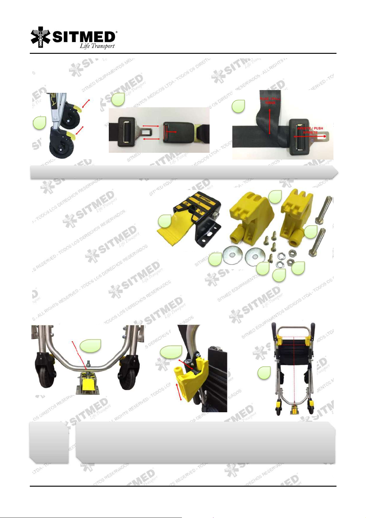
4. Before sitting or lifting the patient from the chair, lock the four casters (J) using the yellow "brake" in each of them. To lock it, simply push
on the outer end of the part, causing it to be pressed against the wheel. To release, step on the opposite end causing the wheel to become
free again. 5. Secure the patient using the safety belt (E). To open or close the belt, press the red button on the top of the engaging part by
inserting or removing the metal coupling. 6. If necessary adjust the strap by pressing the metal coupling and pulling on the top of the strap.
The ambulances chair installation kit contains the following items:
A) 01 – Locking ”Turtle”.
B) 02 – Plastic stoppers.
C) 02 – 5/16 Plater washer.
D) 04 – M6 X 25 self-tapping screws
E) 02 – M8 Pressure washers
F) 02 – M8 Nuts.
G) 02 – M8 X 65 Screws.
1. To install the chair, find a spot inside the ambulance where it can stand without any obstruction. 2. Attach the locking turtle (A) to the king
pin and the plastic stoppers (B) in the rear couplers affixed to the chair. 3. Attach the assembly to the ambulance wall and mark the drilling
to be performed from center to center of each hole. 4. Remove the assembly, drill the marked positions and attach the locking turtle and
plastic stoppers with the supplied hardware. 5. Hold the chair simultaneously on the plastic stoppers and on the locking turtle, making sure it
is firm and secure.
4
5
6
SETTLING
A
B
C
G
D
E
F
2A
2B
4
The rescue chair fasteners were not designed for patient transport. Never carry patients sitting in the chair while
the ambulance is moving.

USER´S MANUAL – Sitmed Equipamentos Médicos Ltda
7
PARTS AND FEATURES
A) Structure in rotomolded polyethylene.
B) Spider-style immobilization belt (optional).
C) Wide handles for transport and head immobilizers adaptation.
Open all the straps of the Spider belt in only one side. Lay the patient on the board performing a block transfer maneuver (A) or a 90
degrees rolling block (B). After lying the patient on the board, pass the open straps on him, adjusting positions as needed and affixing them
on the board, using the specific openings for the passage of the straps.
At the end of immobilization the patient's final position should be equal to that of the image (C). For a more effective and safe
immobilization, a neck collar and head immobilizer should be used. For greater safety it is recommended to transport the patient with four
rescuers, placed in the positions indicated on the illustration (D) placed on positions 1, 2, 3 and 4. Depending on the patient's weight, two
rescuers additional help may be necessary, as they can be placed as illustrated at positions A and B.
Figure A – Block transfer: Lift the patient by keeping the spine stabilized and lying on the board.
Figure B – 90 degrees rolling: Roll the patient sideways, keeping the spine stabilized, placing the board underneath the patient, and roll him back to the original position.
IMMOBILIZATION BOARD MIS 100 – MEDUSE
B
A
C
USAGE SUGGESTION
A
B
The immobilization process presented here is just a suggestion, based on already existing patterns and routines.
The process of immobilizing patients using the board should only be carried out by qualified professionals and must
meet specific regulations or laws of each country, being Sitmed® equipment’s just a facilitator.
The transport of the board inside ambulances or rescue vehicles must be done in niches, specific compartments or
affixed to the structure of the vehicle, avoiding that it moves during possible collisions or overturns. Sitmed is not
responsible for the way the boards are transported inside the vehicles.
C
D
USER´S MANUAL – Sitmed Equipamentos Médicos Ltda
8
PARTS AND FEATURES
A) Structure in hard tubular aluminum.
B) Quick coupling PVC safety belts.
C) Reinforced synthetic base.
D) Fixed casters to slide inside vehicles.
E) Articulated joints in reinforced aluminum profile.
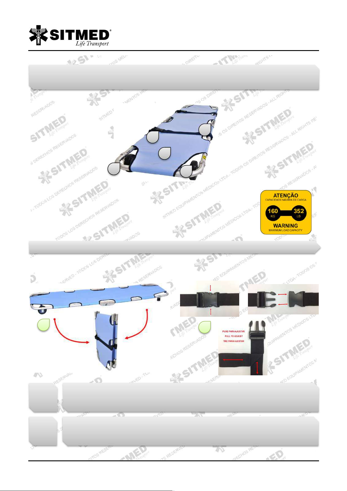
1. The MPS 110 - PANDORA stretcher has one central articulation (E), for opening and closing. For this process simply hold the stretcher
by the edges and fold it in half, both for opening or closing. 2. Lay the patient on the stretcher whether or not immobilized to the
immobilization board. 3. Before transporting someone, lock the patient with the seat belts (B), adjusting the buckle to ensure its stability.
FOLDABLE STRETCHER MPS 110 – PANDORA
D
C
A
B
E
OPERATING INSTRUCTIONS
1
3
The MPS 110 – PANDORA stretcher has a flexible synthetic base, and it is not recommended to transport patients
with suspected cervical spine injury without being properly immobilized with a rigid board.
Do not use the stretcher for any purpose other than transporting patients. Carrying objects can damage its base,
resulting in loss of warranty.

USER´S MANUAL – Sitmed Equipamentos Médicos Ltda
9
PARTS AND FEATURES
A) Rubberized levers for transport.
B) Synthetic reinforced base.
C) Quick coupling PVC safety belts
D) Rubber shoes for ground support.
E) Structure in hard tubular aluminum.
F) Articulated joints in reinforced aluminum profile.
G) Nylon bag for transport and storage.
1. Turn the stretcher with the base facing down. 2. Move the articulated joints in the direction indicated by the arrows. 3. Pull one side of the
stretcher folding it lengthwise. 4. Fold the stretcher. 5. Store the stretcher inside its bag, for transport.
BI-FOLDABLE STRETCHER MPS 120 – PANDORA 2
A
B
D
C
E
F
G
OPERATING INSTRUCTIONS
The MPS 120 - PANDORA 2 stretcher has a flexible synthetic base, and it is not recommended to transport patients with
suspected cervical spine injury without being properly immobilized with a rigid board.
Do not use the stretcher for any purpose other than transporting patients. Carrying objects can damage its base,
resulting in loss of warranty.
When folding the stretcher, be careful to accommodate the synthetic material avoiding it to be placed at any end, which
may tear or damage the it.
1
2
3
4
5

USER´S MANUAL – Sitmed Equipamentos Médicos Ltda
10
PART AND FEATURES
A) Movable or fixed rear handle for transport.
B) Polymer retraction lever.
C) Safety belts with automotive couplings.
D) Steel set with king pin to lock on rear fastener.
E) Rubberized casters with 127mm diameter and brake system.
F) Hard tubular aluminium structure.
G) Density 33 mattress, coated in 100% waterproof material, electronically sewn.
H) Tilting side handles with double trigger.
I) Structural polymer unions of high strength and durability.
J) Anti-fall safety system.
K) Articulated polymer joints.
L) Front stoppers Coated with high impact PVC profile.
M) Adjustable backrest (fowler) with 8 adjusting positions.
N) Air axle with rubberized casters and height adjustment system.
1. Wheel brake: To lock the wheels, step on the bottom of the yellow part (A) and to release step on the top (B). 2. Double trigger side
handles: Press the top of the yellow trigger (C) simultaneously on both sides, lowering the handle. To close again simply return to the
original position. The handle will lock automatically. 3. Movable backrest: Pull the trigger (D). Raise or lower the backrest to the desired
angle, so that it automatically locks in one of 6 positions.
RETRACTILE COT MRS 310 – ESSENTIAL
A
B
D
E
F
C
H
G
M
N
K
L
J
I
USAGE INSTRUCTIONS / BASIC FEATURES
1
3
2
It is always recommended to lock the 4 wheels before placing or removing any patient from the stretcher, especially on
steep or uneven terrain.

USER´S MANUAL – Sitmed Equipamentos Médicos Ltda
11
4. To open or close the seat belt press the red button on top of the piece hitch, introducing or removing the metal hitch. 5. If necessary
adjust the strap pressing the metal latch and pulling the upper part of the belt.
6. For patient safety always use the 4-point seat belt. The 4-point belt should be passed over the patient's shoulders and attached to the
chest belt. 7. The belts must be removed periodically for cleaning or replacement. To remove them or to put them in the cot pass the
couplings inside the base handle, trapping it in the structure of the cot.
The cot ambulance fastener installation kit contains the following items:
A) 01 – Aluminum “V” guide with stoppers.
B) 01 – Locking “turtle”, with adjusting rail.
C) 08 – M8 pressure washer.
D) 08 – M8 X 65 Screws.
E) 08 – Plater washer 5/16.
F) 08 – M6 X 50 self-tapping screw.
G) 08 – M8 nuts.
The first step for installing the cot is to adjust the position of the locking turtle on the lateral side its adjusting rail. For this, loosen the turtle
attachment screws (A), adjust the turtle causing the kingpin orifice to be centered along the rail (B). To finish, retighten the screws (A).
SETTLING
B
C
E
G
D
F
A
4
5
6
7
USER´S MANUAL – Sitmed Equipamentos Médicos Ltda
12
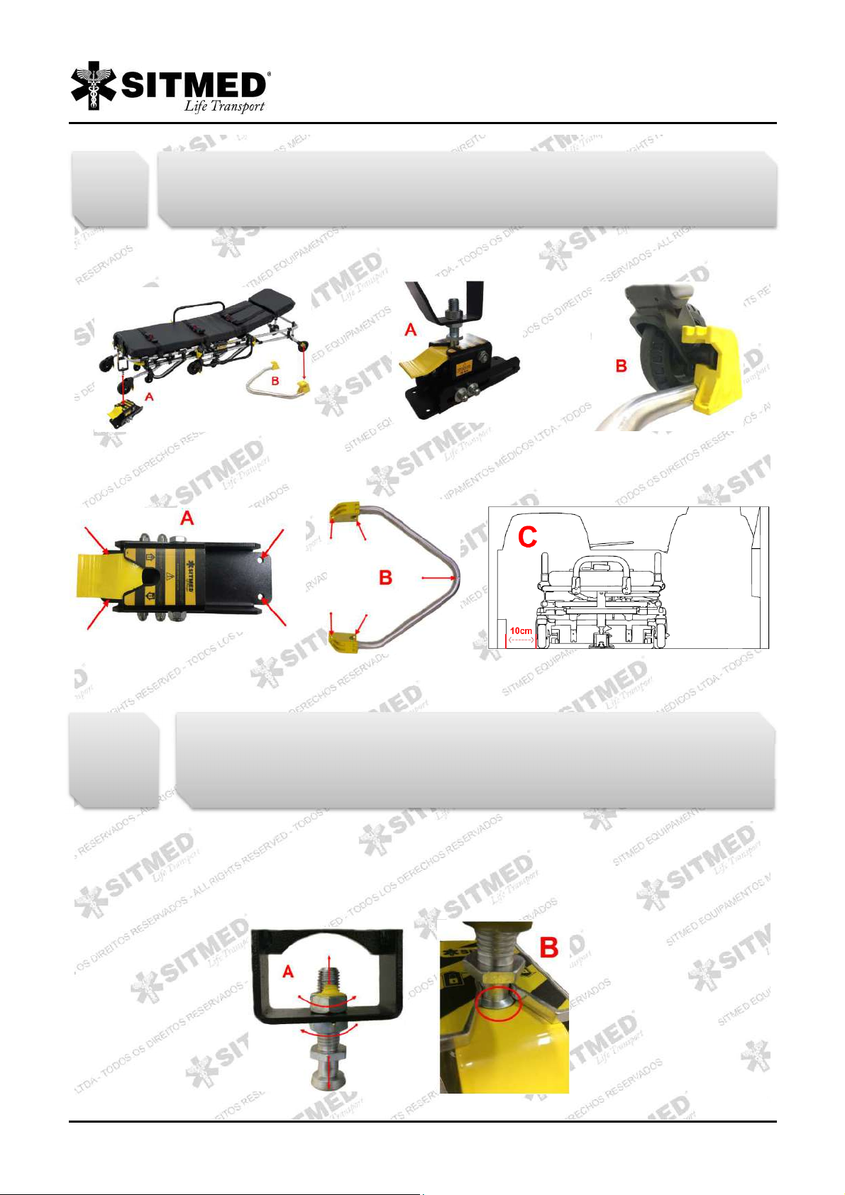
Then place the stretcher inside the ambulance at the desired location for installation. Attach the turtle latch assembly on the king pin (A) and
attach the aluminum guide in air shaft (B). Make sure that both the locking turtle and the frontal guide are firmly in place, without gaps and in
their proper position.
With a pen, mark the drilling to be performed on the floor of the vehicle, both for the locking turtle assembly (A) and for the frontal guide (B).
The necessary holes of each set are indicated by the red arrows. Leave a minimum of 10cm (C) space between the cot and the ambulance
wall / furniture, allowing free movement for the cot wheels.
Remove all parts just leaving the floor with the markings and proceed with the indicated drillings. Make sure the holes are straight and
aligned. Place the locking turtle and frontal guide in the perforated positions and fasten both sets using the screw kit supplied with the cot.
Tighten all nuts and bolts to get them firm and still.
After fixing the sets its necessary to perform a fine adjustment of the king pin and the locking turtle. Test the cot anchorage by placing and
pulling it out of its fastener, with and without weight. The perfect attachment consists of the simultaneous locking of the king pin on the turtle
and the pins of the air-axle on the frontal guide stoppers.
If necessary adjust the height of king pin (A), loosening the nuts and adjusting as necessary. The ideal height of the pin is when its
engagement base is aligned with the locking trigger (B). Also, if necessary, adjust the position of the locking turtle again, as described in the
first step.
Regularly check and tighten the locking turtle. Over time, due to its use, it can slightly move from the rail,
compromising the cots fastening. This adjustment can also be made in the case of replacing or adjusting an
additional cot.
Before drilling the floor of the vehicle, make sure that there are no structural parts such as sleepers, wiring
ropes and, in particular, fuel tanks below the chosen installation points. If there are any, be careful not to drill
them, remove them if necessary or hire the services of a car adapter to perform the proper installation of the
cot.

USER´S MANUAL – Sitmed Equipamentos Médicos Ltda
13
All cots are produced according to the height of the ambulance to be used, but for several reasons it might be necessary an adjustment of
the air-axle wheels height. It is very important that these wheels stay aligned with the height of the ambulance floor (A). If necessary, adjust
the wheels height by removing the bolt and pin (B) transferring them to the lower or upper position as required:
REAR HANDLE:
Your cot have a movable rear handle (A) as factory setup. You can used it in this way or fasten it using the supplied bolts. To fasten it, put it
on vertical position (B) and insert the screws on the indicated place (C). Use appropriate tools to tighten.
1. After the patient has been placed on the cot, proceed to the ambulance. Approach the cot to the ambulance by leaning its frontal PVC
stoppers (L) simultaneously to the vehicle bumpers. 2. Activate the retraction lever by suspending the patient's weight, causing the “knee”
(K) of the cot to be displaced. 3. Push the cot into the ambulance, keeping it in a 100% horizontal position, until it is attached to the fastener
system. Pull the cot to make sure it is securely attached to its fastener.
4. To remove the cot from inside the ambulance, suspend the cot with one hand, and use the other hand to trigger the locking turtle. 5.
Press the locking turtle lever down, releasing the king pin. 6. Pull the stretcher back, holding the locking turtle lever until the complete
release of the king pin. 7. Remove the stretcher from the ambulance by suspending the patient's weight and keeping the stretcher in a 100%
level horizontal position until its full aperture and locking of the articulated knees.
Cots with uneven height from the ambulance floor have a great risk of being dropped when inserted or removed from
the ambulance. If your cot has a height difference between the air-axle wheels and the ambulance floor, discontinue
its use until you adjust the height of the equipment according to the above instructions.
USAGE INSTRUCTIONS / SPECIFIC FEATURES
Any previous procedure for the use of cots that refers to the handling of patients, especially with regard to the
immobilization, transfer and placement of the patient on the equipment, should be performed only by trained
professionals.
1
3
2

USER´S MANUAL – Sitmed Equipamentos Médicos Ltda
14
7
8. For a safer transport of the patient, we recommend the cot to be always operated by at least two trained rescuers placed in positions as
shown in the picture. 9. For obese patients transport or when in very rough terrain with obstacles, we recommend the cot to be operated by
four rescuers, placed in positions as indicated in the image.
PARTS AND FEATURES
A) Movable or fixed rear handle for transport.
B) Steel set with king pin to lock on rear fastener.
C) Polymer retraction lever.
D) Safety belts with automotive couplings.
RETRACTILE COT MRS 340 – TOP MOTION
A
D
H
L
G
E
B
I
C
F
J
M
N
K
O
Be alert when removing the cot from the ambulance while it is parked on steep or uneven terrain. It may be
necessary to tilt the back of the cot for a full aperture and locking of the knees.
9
8
USER´S MANUAL – Sitmed Equipamentos Médicos Ltda
15
E) Structural polymer unions of high strength and durability.
F) Rubberized casters with 200mm diameter and brake system.
G) 33 density mattress, coated in 100% waterproof material, electronically sewn.
H) Tilting side handles with double trigger.
I) Anti-fall safety system.
J) Hard tubular aluminum structure.
K) Articulated polymer joints.
L) Adjustable backrest (fowler) with 8 adjusting positions.
M) Front stoppers coated with high impact PVC profile.
N) Air-axle with rubberized casters and height adjustment system.
O) Custom electrostatic painting on lower frame (optional).
Applies to MRS 340 – TOP MOTION the same instructions presented for the MRS 310 – ESSENTIAL, except for cleaning and disinfecting
the parts that have electrostatic painting. This should be done using only a damp cloth, without the use of any abrasive product.
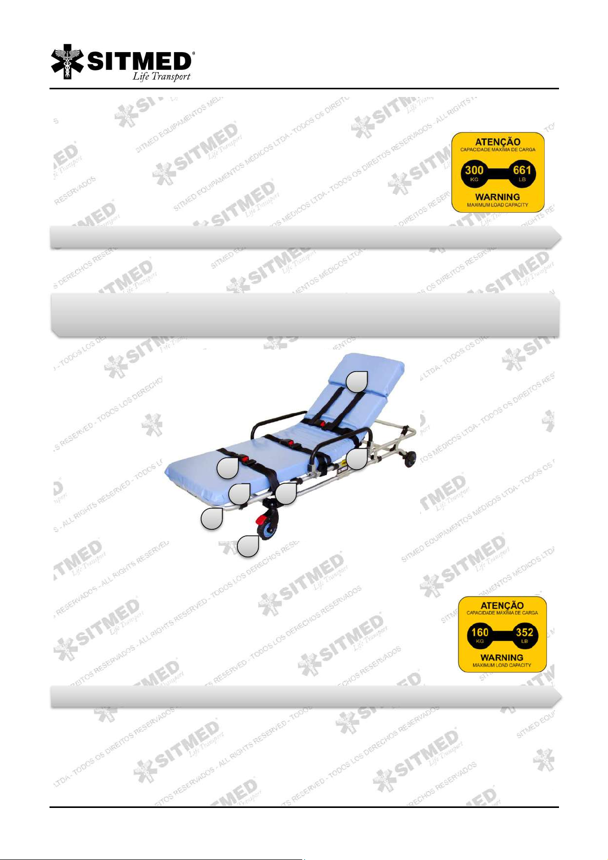
PARTS AND FEATURES
A) Safety belts with automotive couplings.
B) 33 density mattress, coated in 100% waterproof material, electronically sewn.
C) Hard tubular aluminum structure.
D) Rubberized casters with 127mm diameter and brake system.
E) Structural polymer unions of high strength and durability.
F) Adjustable backrest (fowler) with 8 adjusting positions.
G) Tilting side handles.
Applies to MSS 300 – PRIME CARE the same instructions presented for the MRS 310 – ESSENTIAL, with the exception of the retractable
system operation, as PRIME CARE model is devoid of such feature. The operation of this model should be performed as follows.
1. Since it doesn’t have retractable legs, all movement of the PRIME CARE model should be performed in the ground. 2. The transport and
movement of placing or withdrawing it from the interior of the ambulance (3) must always be carried out by at least two rescuers.
STANDARD COT MSS 300 – PRIME CARE
C
B
A
D
E
G
F
USAGE INSTRUCTIONS
USAGE INSTRUCTIONS

USER´S MANUAL – Sitmed Equipamentos Médicos Ltda
16
PARTS AND FEATURES
A) Movable or fixed rear handle for transport.
B) Steel set with king pin to lock on rear fastener.
C) Rubberized caster with 127mm diameter and brake system.
D) Polymer retraction lever.
E) Safety belts with automotive couplings.
F) 33 density mattress, coated in 100% waterproof material, electronically sewn.
G) Structural polymer unions of high strength and durability.
H) Additional 3” casters for ground support.
I) Tilting side handles with double trigger.
J) Anti-fall safety system.
K) Articulated polymer joints.
L) Hard tubular aluminum structure.
M) Adjustable backrest (fowler) with 8 adjusting positions.
N) Front stoppers coated with high impact PVC profile.
O) Air-axle with rubberized casters and height adjustment system.
BI-ARTICULATED COT MWS 320 – LEVEL UP
A
B
D
C
E
F
I
M
O
H
L
N
K
G
J
1
2
3

USER´S MANUAL – Sitmed Equipamentos Médicos Ltda
17
Applies to MWS 320 – LEVEL UP the same instructions presented for the MRS 310 – ESSENTIAL, with an exception for the legs
articulation which are as follows:
Since it has double retraction system, the operation of the LEVEL UP stretcher takes place in two steps: 1. Lean the front stoppers (N)
uniformly to the ambulance bumpers. 2. Pull the left retraction trigger until you move the front knees assembly (K). 3. Push the stretcher,
releasing the retraction trigger until the rear stoppers lean uniformly to the ambulance bumpers.
4. After leaning the rear stoppers to the ambulance, pull the right retraction lever (5), pushing the stretcher completely into the ambulance
(6), until it locks to the fastener system.
The IV Pole and the O² cylinder holder are both sold separately, and may be attached to the Sitmed stretchers. In the case of your stretcher
having one of those accessories, please proceed as follows:
IV POLE
1. Arm the bracket lifting the rod (A) in position 90 degrees until the yellow trigger automatically locks into the base of the bracket. 2. Open
the hitch hooks and if necessary extend the rod, turn the rod counterclockwise (B) to release and pull upward (C) by turning clockwise to
lock. 3. To store the IV pole press the yellow trigger (D) and rotate it to the horizontal position.
USAGE INSTRUCTIONS
1
3
2
4
5
6
Be aware while removing the stretcher from the ambulance when it’s parked on steep or uneven terrain. It may be
necessary to tilt the front and rear of the stretcher for fully opening and locking of the knees.
IV POLE AND O² CYLINDER HOLDER
1
2
3

USER´S MANUAL – Sitmed Equipamentos Médicos Ltda
18
O² CYLINDER HOLDER
1. Sitmed’ cylinder holder is designed to accommodate cylinder up to 23cm in diameter. To fasten the cylinder, use the Velcro straps (A), By
passing them through the bars on the back of the holder. 2. The holder should be carried in one of the side handles of the stretcher. To fit
the holder, tilt it slightly (B) and attach the rear tabs on the side handle (C). This operation serves both for placement and withdrawing the
support. 3. A wall clip also comes along. To allow the holder / cylinder to be carried inside the ambulance (D). To install the clip choose a
free wall inside the ambulance, brace the clip on the wall, mark the hole and secure with the supplied hardware.
PARTS AND FEATURES
A) Slim, lightweight and compact.
B) Additional support casters.
C) Rubber castors with a diameter of 127mm and a brake system.
D) Safety belts with automotive locks.
E) Mattress density 33, coated in 100% waterproof material, sewn electronically.
F) Lateral collapsible handles with double lock system.
G) Backrest (fowler) with adjustment in 8 positions.
H) Aerial axle with rubberized castors and height adjustment system.
I) Telescopic system for articulation of the legs.
J) Legrest with multiple positions.
K) IV Pole
L) Medrac
BI-ARTICULATED COT MWS 320 – LEVEL UP II
A
G
F
D
B
E
C
C
H
I
J
K
L

USER´S MANUAL – Sitmed Equipamentos Médicos Ltda
19
The same instructions of the model MRS 310 - ESSENTIAL, including instructions for basic operations, installation in ambulances and
adjustments are applied to model MWS 320 - LEVEL UP II.
Since it has a double retraction system, the operation of the LEVEL UP cot occurs in two steps: 1. Press the front legs touch evenly against
the ambulance bumpers. 2. Pull the left retraction lever until the telescopic system is moved. 3. Push the cot by loosening the retraction
lever until the rear legs touch evenly against the ambulance bumpers.
4. Engage the right retraction lever until the telescopic system is moved, and 5. push the cot into the ambulance until it locks at the fasten
system. 6. To remove the cot from the ambulance release it from the fasten system by pressing the locking lug as per instructions in this
manual. Pull the cot out of the ambulance without pulling any levers, suspending the patient's weight and keeping the cot 100% level in the
horizontal position. Pull it until both legs lower by gravity and the telescopic system locks automatically.
INDEPENDENT RETRACTION SYSTEM:
The LevelUp cot features an independent leg retraction system. Such a system allows greater ergonomics and less effort for the operator at
the moment of loading and unloading the cot from the interior of the ambulance. Be aware during operation of the cot for the correct
actuation of the retraction systems. The lever (1) drives the retraction assembly of the front legs and the lever (2) drives the retraction
assembly of the rear legs.
USAGE INSTRUCTIONS / BASIC INSTRUCTIONS
USAGE INSTRUCTIONS / SPECIFIC INSTRUCTIONS
1
2
3
5
4
6

USER´S MANUAL – Sitmed Equipamentos Médicos Ltda
20
O2 BRACKET:
Level Up 2018 has bracket for O2 cylinder sold separately as an accessory. 1. To fit the cylinder into the holder lay the cylinder in the
horizontal position with the valve facing the opening. 2. Use the Velcro straps to fasten the cylinder.
LEG REST:
The Level Up II have a leg rest system that becomes possible put the patient leg in several positions, including: Semi Trendelenburg,
cardiac or vascular. To arm the leg rest use the two hands to pull up the system (A), until the chromo lever clip in the cavity (B). To low
down the system pull it up using one hand (C) and with other hand push forward the chromo lever (D).
To put the leg rest in second position use your both hands to pull up the straps (E) until the hooks clip in the under cavity (F). To back to the
original position just pull up the system using your both hands (G).
MULTI POSITIONS SYSTEM:
If your cot has the multi positions system you can use it to put the patient in several positions, including: Fowler position, Trendelenburg and
RCP position. To put the patient in fowler position pull the lever (2) and low down the rear side of the cot (A).
Use the retraction levers only at the moment of loading the cot into the ambulance. Be careful not to push the levers
while transporting patients as this may cause the cot to fall.
1
2
Be careful at the moment to low down the system, mainly with the patient in the cot. You must suspend the legs weight with
just one hand. If you aren´t safe to operate ask for additional help. Keep attention to don´t injure fingers and hands.
This manual suits for next models
8
Table of contents
Popular Mobility Aid manuals by other brands


Rehasense
Rehasense Server W user manual

Invacare
Invacare Reliant 440 Owner's operator and maintenance manual

Otto Bock
Otto Bock Veldink4kids Kiddo Classic Instructions for use

Rehasense
Rehasense ROUTER user manual

Jenx
Jenx MUS02-FP-08 Instructions for use

Petermann
Petermann Alpha Support Belt Merlin manual