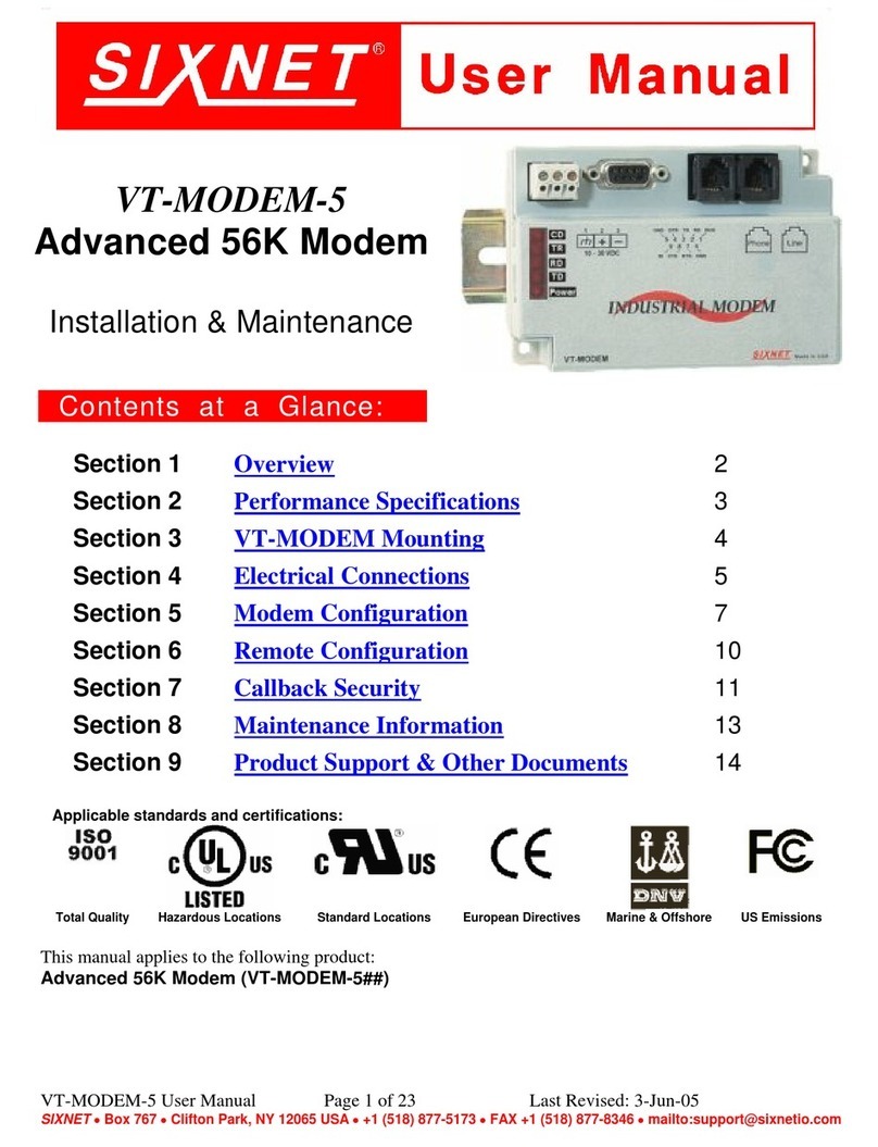
Sixnet VT-MODEM-1US Instruction Manual

Technical Note #623
SIXNET • 331 Ushers Rd. • Clifton Park, NY 12065 USA • +1 (518) 877-5173 • FAX +1 (518) 877-8346 • [email protected]
TN623.DOC PAGE 1 of 9 REV: APRIL 2002
VT-MODEM Interfaces with the Allen-Bradley MicroLogix 1500 PLC using
Rockwell’s RSLogix 500 & RSLINX Lite Software
Abstract: The information in this document was provided by Rock Interface Systems, Inc. It
explains the procedure for interfacing a SIXNET Industrial Telephone Modem with an AB
MicroLogix 1500 controller and a computer running the Rockwell RSLogix 500
programming software and the RSLINX communication software. This setup will allow a
remote computer to go on-line with a MicroLogix via a telephone modem connection.
Hardware and Software Used:
· SIXNET Industrial Modem (Part Number: VT-MODEM-1US)
· Serial cable (Part Number: VT-CABLE-MDM) (Incl. with VT-MODEM-1US)
· SIXNET VT-MODEM Setup Wizard v1.15
· Allen-Bradley MicroLogix 1500 CPU (i.e. 1764-LSP)
· Allen-Bradley Advanced Interface Converter (i.e. 1761-NET-AIC)
· Allen-Bradley HHP cable for AIC module to CPU port connection (i.e. 1761-CBL-HM02,
Ser.B)
· Allen-Bradley cable for PC to Micrologix processor (i.e. 1761-CBL-PM02, Ser.B)
· Null modem adapter cable
· Rockwell RSLogix Software v3.01.02.00
· Rockwell RS LINX Communication Driver v2.10.118.0
· Internal Modem on PC
· Analog phone line connections at both ends (digital lines may not work). The phone line at
the MicroLogix end must also be a direct-dial number from the outside (It is recommended
that if possible the analog line should not be routed through a PBX system).
(Note: The Micrologix 1000 can be used as an alternative to the Micrologix 1500.)
Pin-out of Null Modem Adapter Cable
DB9 Male to Modem DB9 Male to 1761-CBL-
PM02
CD 1
®1 CD
RD 2
®3 RD
TD 3
¬2 SD
GND 5 5 GND
RTS 7
®8 CTS
CTS 8
¬7 RTS

SIXNET • 331 Ushers Rd. • Clifton Park, NY 12065 USA • +1 (518) 877-5173 • FAX +1 (518) 877-8346 • [email protected]
TN623.DOC PAGE 2 of 9 REV: APRIL 2002
Receiving Modem (SIXNET VT-MODEM-1) Setup Procedure :
Use Window’s HyperTerminal to communicate to the modem.
Note: For information on how to use HyperTerminal, please consult the SIXNET VT-MODEM
online help guide located on the SIXNET CD in the Product Catalog.
Settings can be changed by connecting the straight through cable, which comes as part of the Industrial
Modem package (VT-CABLE-MDM) to the serial port on the modem and the serial port of the computer
(i.e. serial port COM1).
Important: Choose the baud rate that matches the PLC or other device that will be connected to
the modem. Anytime a setting is saved using &W0 or &W1, the RS232 baud rate is memorized
by the VT-Modem. The saved baud rate will be used for future communications with any
attached device that does not initiate communications with the modem (such as most PLC’s).
To check communication, type AT <Enter>. OK should appear.
To Set Up Modem:
Type In: AT&F<Enter>- This sets the modem to factory defaults
Type In: ATS0=1<Enter>- This set the modem to auto-answer
Type In: ATS46=136 <Enter>- This turns off data compression
Type In: AT&W0&W1<Enter>- This save changes to both profiles
Type In: AT&V<Enter>- Use this to verify changes
(Note: Using a Rev 1.09 VT-MODEM-1, Rev 1.04 VT-MODEM-2, Rev 1.02 VT-MODEM-3 may
require different AT commands. Loading pre-configured settings from the latest VT-MODEM Setup
Wizard will eliminate the need of AT commands.)
Loading Pre-Configured Settings:
SIXNET provides a pre-configured file (AB_Micrologix1500.6ms and AB_Micrologix1000.6ms) that
can be loaded to the modem via the VT-MODEM Setup Wizard; a Setup Utility included with every
SIXNET VT-MODEM-#. The AB_Micrologix1500.6ms file is located on the latest SIXNET CD, from
your local SIXNET representative, or in the modem section at www.Get2Support.com.
To load the pre-configured file into the modem click on the “Open Configuration File” button in the
Load Configuration window, and open the AB_Micrologix1500.6ms file (See Screen Shot 1). Select the
communications port the SIXNET VT-MODEM-1 is connected to (COM 2 in this case) in the COM
Parameters window (See Screen Shot 2). Load the configuration into the modem using the “Write
Configuration to the Modem” button in the Write Configuration Window (See Screen Shot 3).

SIXNET • 331 Ushers Rd. • Clifton Park, NY 12065 USA • +1 (518) 877-5173 • FAX +1 (518) 877-8346 • [email protected]
TN623.DOC PAGE 3 of 9 REV: APRIL 2002
Screen Shot 1
Screen Shot 2

SIXNET • 331 Ushers Rd. • Clifton Park, NY 12065 USA • +1 (518) 877-5173 • FAX +1 (518) 877-8346 • [email protected]
TN623.DOC PAGE 4 of 9 REV: APRIL 2002
Screen Shot 3
MicroLogix 1500 Controller Channel Configuration:
Whatever PLC program is running in the processor is not important; however the programming port
Channel 0 system port must be configured properly and the changes saved with the program.
a) Start up RSLogix and go on-line (this requires the 1761-CBL-PM02 cable connected to
channel 0). Double click on the channel configuration. Select Channel 0 - System.
b) The Channel Configuration must be set up so that the modem will properly communicate
with the MicroLogix 1500. Make sure that the following parameters match those of the
MicroLogix 1500 Channel Configuration.
IMPORTANT: To communicate to the Channel 0 port after making the following changes,
follow the directions below:
When the Channel 0 settings have been changed, the 1761-CBL-PM02 cable can be removed between
the computer and the MicroLogix 1500. The 1761-CBL-HM02 cable must now be installed between the
AIC module and the Channel 0 Port of the Micrologix 1500 processor.

SIXNET • 331 Ushers Rd. • Clifton Park, NY 12065 USA • +1 (518) 877-5173 • FAX +1 (518) 877-8346 • [email protected]
TN623.DOC PAGE 5 of 9 REV: APRIL 2002

SIXNET • 331 Ushers Rd. • Clifton Park, NY 12065 USA • +1 (518) 877-5173 • FAX +1 (518) 877-8346 • [email protected]
TN623.DOC PAGE 6 of 9 REV: APRIL 2002

SIXNET • 331 Ushers Rd. • Clifton Park, NY 12065 USA • +1 (518) 877-5173 • FAX +1 (518) 877-8346 • [email protected]
TN623.DOC PAGE 7 of 9 REV: APRIL 2002
Connecting the Modem to the Micrologix:
Connect the 1761-CBL-PM02 ser B to the MicroLogix 1500’s Channel 0. Use a male-to-female DB9
null modem adapter to connect the 1761-CBL-PM02 ser B to the modem.
Sending Modem Setup Procedure:
Open the control panel in Windows 98 (if applicable) and double-click on the modem icon. This will
bring up a dialog box showing the modem properties. Make a note about which COM port the modem is
set up on. If it is COM1 or COM2, then record this. If it is COM3 or COM4, then the exact IRQ and
memory address must be obtained for the number shown and the address shown. Click on the OK
button and then on the General tab, press the “Properties” button. Make sure modem properties match
those listed on the following pages:

SIXNET • 331 Ushers Rd. • Clifton Park, NY 12065 USA • +1 (518) 877-5173 • FAX +1 (518) 877-8346 • [email protected]
TN623.DOC PAGE 8 of 9 REV: APRIL 2002

SIXNET • 331 Ushers Rd. • Clifton Park, NY 12065 USA • +1 (518) 877-5173 • FAX +1 (518) 877-8346 • [email protected]
TN623.DOC PAGE 9 of 9 REV: APRIL 2002
RSLogix Driver Setup:
Under Configure Dialer just enter the phone number and when you communicate the Rockwell software
will automatically dial and make the phone connection. (Note: When configuring RSLINX to work with
the Micrologix 1000 set the Error Checking to CRC.)
Other Sixnet Modem manuals
Popular Modem manuals by other brands
Zoom
Zoom 3035 Specification sheet

Ebyte
Ebyte E90-DTU 230SL30-GPRS user manual

Home Automated Living
Home Automated Living HAL Voice Portal installation guide
Campbell
Campbell COM320 instruction manual
Datum Systems
Datum Systems PSM-500 Installation and operation manual
Sierra Wireless
Sierra Wireless DART 200 CDPD Modem user guide
