Sixnet IndustrialPro User manual

IndustrialPro™ and MobilityPro™ Gateway
Wireless Modems
User's Guide
Version 1.11
Novemeber 2, 2011

IndustrialPro™ and MobilityPro™ Gateway
User's Guide
Copyright © 2010 Sixnet LLC. All rights reserved.
2
1.11 –November 2, 2011
No part of this publication, or any software included with it, may be reproduced, stored in a retrieval system, or
transmitted in any form or by any means, including photocopying, electronic, mechanical, recording or otherwise,
without the prior written permission of the copyright holder.
Sixnet, LLC (Sixnet) provides this document as is, without warranty of any kind either expressed or implied including, but
not limited to, the implied warranties of merchantability and fitness for a particular purpose. Sixnet may make changes
of improvements in the equipment, software, or specifications described in this document at any time and without
notice. These changes may be incorporated in new releases of this document.
This document may contain technical inaccuracies or typographical errors. Sixnet and its subsidiaries waive responsibility
for any labor, materials, or costs incurred by any person or party as a result of using this document.
Sixnet and any of its subsidiaries or other affiliates shall not be liable for any damages (including, but not limited to,
consequential, indirect or incidental, special damages, or loss of profits or data) even if they were foreseeable and Sixnet
has been informed of their potential occurrence arising out of or in connection with this document or its use.
Computer Software Copyrights
The products described in this manual include copyrighted Sixnet computer programs stored in semi-conductor
memories or other media. Laws in Canada, the United States and other countries preserve for Sixnet certain rights for
copyrighted computer programs, including the exclusive right to copy or reproduce in any form the copyrighted
computer program. Accordingly, any copyrighted Sixnet computer programs contained in the Sixnet products described
in this manual may not be copied without the express written permission of Sixnet.
Furthermore, the purchase of Sixnet products shall not be deemed to grant either directly or by implication, estoppels,
or otherwise, any license under the copyrights, patents or patent applications of Sixnet, except for the normal non-
exclusive, royalty-free license to use that arises by operation of laws in the sale of a product.
Sixnet, LLC
2425, 46th Avenue,
Lachine, Quebec H8T 3C9, Canada
Phone: 1-514-422-9110 option 2
Toll Free: 1-877-422-9110 option 2
Fax: 1-514-422-3338
Web: www.sixnet.com

IndustrialPro™ and MobilityPro™ Gateway
User's Guide
Copyright © 2010 Sixnet LLC. All rights reserved.
3
1.11 –November 2, 2011
Liability Notice
While every effort has been made to achieve technical accuracy, information in this document is subject to change
without notice and does not represent a commitment on the part of BlueTree Wireless Data, Inc., or any of its subsidies,
affiliates, agents, licensors, or resellers. There are no warranties, express or implied, with respect to the content of this
document.
Declaration of Conformity
The device complies with Part 15 of FCC rules and with ICES-003 of Industry Canada Rules. Operation is subject to the
following two conditions:
This device may not cause harmful interference
This device must accept any interference received, including interference that may cause undesired
operation
This equipment generates uses and can radiate radio frequency energy and, if not installed and used in accordance with
the manufacturer's instructions, may cause interference harmful to radio communications. However, there is no
guarantee that interference will not occur in a particular installation. If this equipment does cause harmful interference
to radio or television reception, which can be determined by turning the equipment off and on, the user is encouraged
to try to correct the interference by one or more of the following measures:
Reorient or relocate the receiving antenna
Increase the separation between the equipment and receiver
Connect the equipment into an outlet on a circuit different from that to which the receiver is
connected
Consult the dealer or an experienced radio/TV technician for help.
WARNING
To comply with RSS-102 Health Canada Safety Code 6, the antenna(s) used for this transmitter must be installed to
provide a separation distance of at least 10 cm from all persons and must not be co-located or operating in conjunction
with any other antenna or transmitter. Users and Installers must be provided with antenna installation instruction and
transmitter operating conditions for satisfying RF exposure compliance.
BT-6000 series barrel power connector shall not be used in hazardous locations.

IndustrialPro™ and MobilityPro™ Gateway
User's Guide
Copyright © 2010 Sixnet LLC. All rights reserved.
4
1.11 –November 2, 2011
Change history
Version
Date
Description
1.11
November 2, 2011
Updated to cover BT-5x30 models
1.10
September 27, 2010
Update event and store and forward sections
Update environmental specifications
1.9
June 7, 2010
Add modem pictures Sixnet labels
1.8
March 30, 2010
Change document format

IndustrialPro™ and MobilityPro™ Gateway
User's Guide
Copyright © 2010 Sixnet LLC. All rights reserved.
5
1.11 –November 2, 2011
Table of content
1Product Overview ...............................................................................................................................................8
1.1 Introduction ............................................................................................................................................................... 8
1.2 Modem features ...................................................................................................................................................... 10
1.3 Specifications ........................................................................................................................................................... 11
2BlueVue Device Manager (BVDM)......................................................................................................................22
2.1 Connecting to the modem ....................................................................................................................................... 23
2.2 Software overview ................................................................................................................................................... 25
3AT Commands...................................................................................................................................................26
3.1 Access....................................................................................................................................................................... 26
4Activation & WAN Setup ...................................................................................................................................27
4.1 Activation (CDMA modems only)............................................................................................................................. 27
4.2 WAN Setup............................................................................................................................................................... 28
5LAN Setup .........................................................................................................................................................31
5.1 Ethernet and USB LAN ............................................................................................................................................. 31
5.2 LAN configuration .................................................................................................................................................... 31
5.3 Wireless(WiFi).......................................................................................................................................................... 32
5.4 DHCP server ............................................................................................................................................................. 32
5.5 Dial-up Networking (DUN) over serial ..................................................................................................................... 32
6IP Networking Features .....................................................................................................................................34
6.1 Port-forwarding ....................................................................................................................................................... 34
6.2 DMZ.......................................................................................................................................................................... 35
6.3 IP pass-through ........................................................................................................................................................ 36
6.4 Dynamic IP registration............................................................................................................................................ 37
6.5 IP Security (IPSEC) .................................................................................................................................................... 38
6.6 Access Control List (ACL).......................................................................................................................................... 38
6.7 Password protection ................................................................................................................................................ 38
7Serial IP.............................................................................................................................................................40
8GPS...................................................................................................................................................................41
8.1 GPS protocols........................................................................................................................................................... 42
8.2 Odometer................................................................................................................................................................. 42
8.3 Configuring the modem for GPS reporting.............................................................................................................. 42
9I/O Management ..............................................................................................................................................44
9.1 Digital Output control .............................................................................................................................................. 44
9.2 Digital Input state query .......................................................................................................................................... 44
9.3 Analog Input value query......................................................................................................................................... 45
10 Event Reporting ...........................................................................................................................................46
10.1 Events .................................................................................................................................................................. 46
10.2 Store and forward................................................................................................................................................ 46
10.3 Actions ................................................................................................................................................................. 47
10.4 Reports ................................................................................................................................................................ 47
11 Hardware Installation ..................................................................................................................................49
11.1 Mounting the BT-5x00v2 series modem ............................................................................................................. 49

IndustrialPro™ and MobilityPro™ Gateway
User's Guide
Copyright © 2010 Sixnet LLC. All rights reserved.
6
1.11 –November 2, 2011
11.2 Mounting the BT-6000 series modem................................................................................................................. 49
11.3 Cellular antenna................................................................................................................................................... 49
11.4 Ethernet cable ..................................................................................................................................................... 51
11.5 USB cable ............................................................................................................................................................. 51
11.6 Serial cable........................................................................................................................................................... 51
11.7 Power source ....................................................................................................................................................... 51
12 Appendixes..................................................................................................................................................53
12.1 BlueVue Device Manager Troubleshooting......................................................................................................... 53
12.2 Activation Troubleshooting ................................................................................................................................. 57
12.3 Troubleshooting .................................................................................................................................................. 60
12.4 Firmware Upgrades ............................................................................................................................................. 64
12.5 Sending AT Commands........................................................................................................................................ 66
12.6 Dial-Up Networking in Windows ......................................................................................................................... 68
12.7 Warranty.............................................................................................................................................................. 70
12.8 Customer Support ............................................................................................................................................... 71

IndustrialPro™ and MobilityPro™ Gateway
User's Guide
Copyright © 2010 Sixnet LLC. All rights reserved.
7
1.11 –November 2, 2011
FiguresFigure 1 - Router mode............................................................................................................................................. 9
Figure 2 - IP pass-through mode............................................................................................................................................. 9
Figure 3 –Serial connector (looking at back of modem) ...................................................................................................... 21
Figure 4 –The different ways to connect to a modem......................................................................................................... 23
Figure 5 –Connecting to a remote modem.......................................................................................................................... 24
Figure 6 –Confirming the success of activation ................................................................................................................... 28
Figure 7 –Editing the account information .......................................................................................................................... 29
Figure 8 –Testing the connection......................................................................................................................................... 30
Figure 9 –Default LAN IP configuration................................................................................................................................ 31
Figure 10 –Sample modem configuration for communicating with a device that has the IP 10.127.0.17 ......................... 32
Figure 11 –Port-forwarding entries...................................................................................................................................... 35
Figure 12 –Enabling DMZ ..................................................................................................................................................... 36
Figure 13 –Enabling IP passthrough..................................................................................................................................... 36
Figure 14 –Enabling Dynamic IP Registration ...................................................................................................................... 38
Figure 15 –Enabling password protection ........................................................................................................................... 39
Figure 16 –Serial IP............................................................................................................................................................... 40
Figure 17 –GPS configuration screen ................................................................................................................................... 41
Figure 18 –Modem with good signal strength ..................................................................................................................... 57
Figure 19 –Phone number being displayed on the Modem Diagnostic screen after activation ......................................... 58
Figure 20 –WAN IP being displayed after the modem successfully connects to the cellular network ............................... 59
Figure 21 –Upgrading the firmware..................................................................................................................................... 65
Figure 22 –Creating a new connection in Windows XP ....................................................................................................... 68
TablesTable 1 –Modem features ....................................................................................................................................... 10
Table 2 –General specifications ........................................................................................................................................... 11
Table 3 - 4-pin Molex connector (BT-5000v2) ...................................................................................................................... 15
Table 4 - 4-pin Molex connector (BT-6x00)........................................................................................................................... 15
Table 5 - 4-pin screw terminal (BT-6xx1) .............................................................................................................................. 16
Table 6 –DC 2.5mm Barrel adapter (BT-6000) ..................................................................................................................... 16
Table 7 –Power consumption .............................................................................................................................................. 17
Table 8 –LEDs ....................................................................................................................................................................... 20
Table 9 –Reset button functions.......................................................................................................................................... 21
Table 10 –DHCP IP assignment ............................................................................................................................................ 31
Table 11 –NMEA messages information .............................................................................................................................. 42
Table 12 –dB loss per 100 feet of cable type ....................................................................................................................... 49
IndustrialPro™ and MobilityPro™ Gateway
User's Guide
Copyright © 2010 Sixnet LLC. All rights reserved.
8
1.11 –November 2, 2011
1Product Overview
1.1 Introduction
The BlueTree 5000v2 and 6000 series modems are rugged cellular modems built to provide simple and reliable
communication over a CDMA or GSM cellular data networks. They are typically used in applications such as Public
Safety, Transportation, Vehicle Tracking, Telemetry, SCADA, Remote / Temporary Offices, Landline Replacement, and
WAN backup / Business Continuity.
The models covered by this document are:
Type
CDMA EvDO.A
GSM EDGE
GSM HSPA
MobilityPro™ Gateway
Standalone GPS
BT-5600v2
BT-5800v2
Standalone GPS with Wi-Fi
BT-5630
BT5830
IndustrialPro™ Gateway
4-pin power connector
BT-6600
BT-6800
Screw-block power connector
BT-6601
BT-6401
BT-6801
PoE power input
BT-6601EB
BT-6401EB
BT-6801EB
Ethernet Switch
BT-6621
BT-6421
BT-6821
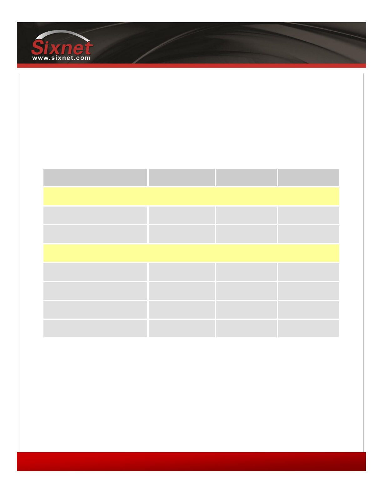
The modem supports two operational modes: router mode, and IP pass-through mode.
1.1.1 Router mode
In Router mode, which is the default mode, the modem manages local and wireless connections independently, and is
capable of routing data packets back and forth between the two.
IndustrialPro™ and MobilityPro™ Gateway
User's Guide
Copyright © 2010 Sixnet LLC. All rights reserved.
9
1.11 –November 2, 2011
Figure 1 - Router mode
The modem manages two connections at the same time, thus acting as a gateway/router:
Cellular WAN connection: This is the Wide Area Network connection to the cellular
network/Internet. The modem can be configured to automatically and autonomously
establish a packet data connection to the cellular carrier and acquire a WAN IP address.
LAN connection: This is the local connection between the modem and any device attached to
its Serial / Ethernet / USB ports. In the case of Ethernet and USB, the modem acts as a
DHCP server and assigns a private LAN IP address to the attached device.
The modem then routes packets back and forth between its WAN and LAN connections, and in turn allows the locally
attached device to communicate with computers or devices at a remote location.
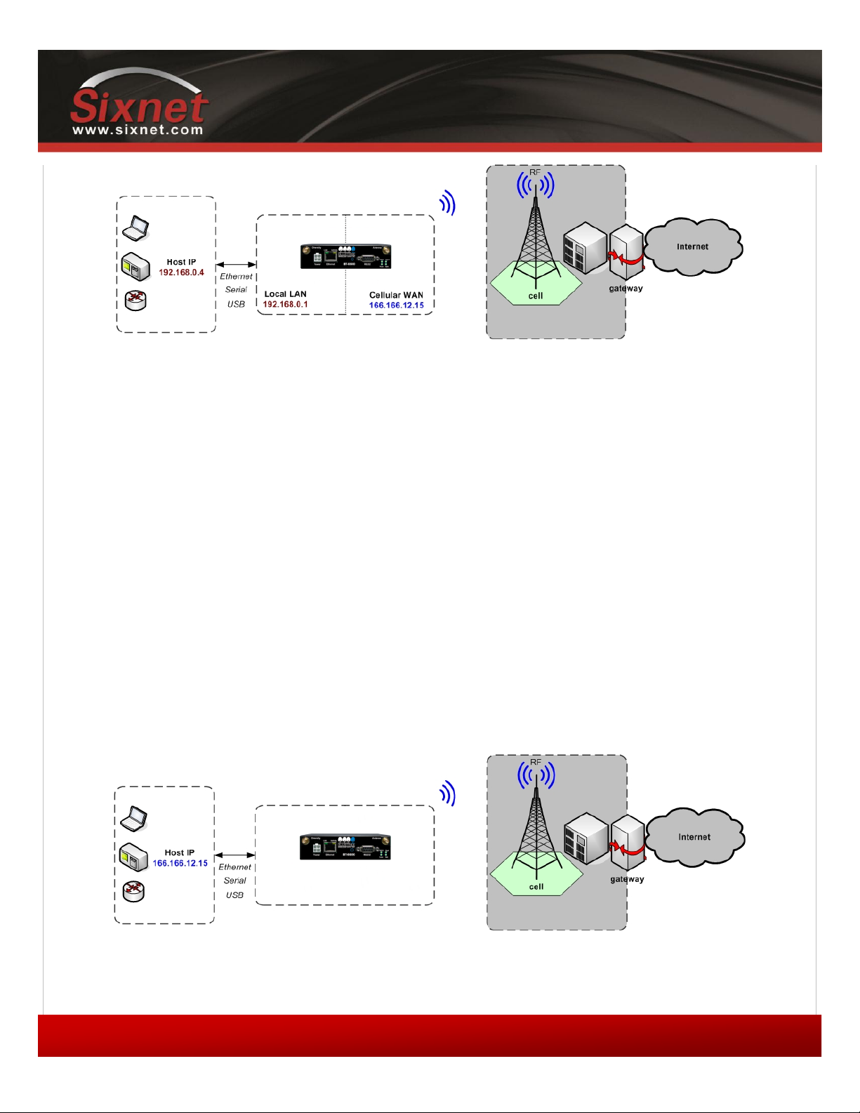
1.1.2 IP pass-through mode
In IP pass-through mode, the modem assigns its WAN IP address directly to the attached host, thus becoming a fully
transparent actor in the communication process. The modem remains reachable through its reserved TCP and UDP ports
so that remote administration and configuration is still possible. Note that this mode allows only one IP address to be
assigned to the first connected device via DHCP (This configuration is not recommended for BT-6x21).
Figure 2 - IP pass-through mode

IndustrialPro™ and MobilityPro™ Gateway
User's Guide
Copyright © 2010 Sixnet LLC. All rights reserved.
10
1.11 –November 2, 2011
1.2 Modem features
Table 1 –Modem features
3 different data
connection interfaces
Serial/RS-232/COM, Ethernet, and USB
Ethernet switch
Available on the BT-6x21 models only. These models have
an embedded 5-port Ethernet switch.
Power-over-Ethernet
Models ending in EB (BT-6x01EB) are models with built in
power sourcing. Power-over-Ethernet compatible devices
can be powered simply by connecting it to the modem’s
Ethernet port.
Autonomous &
persistent connection
management
Fully integrated TCP/IP protocols allow the modem to
connect autonomously to the packet network (Internet). This
feature enables capabilities such as: in-call diagnostic,
Serial-IP, stand-alone GPS, remote configuration and remote
firmware upgrades.
DHCP server
The modem’s DHCP server allows easy administration and
setup of the local network by automating IP address
assignment
IP pass-through
The modem can assign its WAN IP address to the attached
host, thus disabling the DHCP server’s Network Address
Translation. Even when performing pass-through, the
modem remains reachable for remote administration
through its reserved TCP ports.
IP security
The modem can be configured with up to 10 IPSEC tunnels
for increased security in communications.
In-call diagnostic
The user can get modem status information while in a data
call, without interrupting the data session
Serial IP
The modem can provide a reliable means of communication
with serial-only legacy devices. It can encapsulate data
coming from the serial port into a TCP or UDP packet and
send it to a remote server on the packet network or
Internet. It can decapsulate IP packets coming from the
network and send raw data to the serial port.
Remote configuration
The modem can be remotely configured or diagnosed using
BlueVue Device Manager or a terminal session
Remote firmware
upgrade
The modem’s firmware can be remotely upgraded using
BlueVue Device Manager software
Password protection
The modem’s configuration can be protected from tampering
by requesting the user to enter a password before the
existing modem configuration can be viewed or modified

IndustrialPro™ and MobilityPro™ Gateway
User's Guide
Copyright © 2010 Sixnet LLC. All rights reserved.
11
1.11 –November 2, 2011
Integrated GPS receiver
BT-5000v2 models include a GPS receiver for Automatic
Vehicle Location (AVL). The modem can report this
positioning data locally to any of the local data interfaces
(serial, Ethernet, or Ethernet-over-USB), and/or remotely to
a predefined server (see stand-alone).
Standalone GPS
BT-5000v2 modems can be used for remote asset tracking
by sending GPS data to a remote server without the need for
a client application or computer connected to the modem.
Store and forward
If a unit loses its connection to the cellular network, the
event data being collected from I/O, GPS and other sources
will be stored in memory and automatically forwarded when
the connection is reestablished. This is available when using
TCP (with or without BEP ACK) or UDP (with BEP ACK only).
Inputs and outputs
Sensors can be connected to the I/O ports of the modem.
Depending on models, the modem is capable of monitoring
up to four digital inputs for any change in state, and up to
three analog inputs for changes in gradient data sources.
The modem also has up to three digital outputs that can be
used to remotely trigger relays.
The inputs and outputs can be used with the event reporting
protocol to allow automatic reports and triggers.
Event reporting
The modem can send a report to up to 10 destinations when
a user-defined event is triggered. Up to 30 events can be
defined based on I/O signals, GPS data, RF status. The
modem has an embedded event reporting protocol that
automatically formats the messages reported to the remote
server.
Mobile Originated
Management
The modem can connect to a remote server and perform
management actions (firmware upgrade, configuration
changes …). This feature uses Event Reporting.
Partner apps
The modem can host partner applications used for example
to report cellular traffic usage, vehicle diagnostics, alarms, …
1.3 Specifications
1.3.1 General specifications
Table 2 –General specifications
Wireless interfaces
CDMA EvDO.A models
Dual-band CDMA2000 EVDO Rev. A (with diversity)
Backward compatible with 1xRTT and IS95
GSM EDGE Models
Quad-band 850/900/1800/1900 GSM
Backward compatible with Quad-band GPRS/UMTS
GSM HSPA Models

IndustrialPro™ and MobilityPro™ Gateway
User's Guide
Copyright © 2010 Sixnet LLC. All rights reserved.
12
1.11 –November 2, 2011
Quad-band 800/850/1900/2100 MHz WCDMA (with diversity)
HSDPA/HSUPA/HSPA
Backward compatible with GPRS/EDGE/UMTS
Peak data rates
Download: CDMA –3.1Mbps / EDGE –384 kbps / HSPA - 7 Mbps
Upload: CDMA - 1.8 Mbps / EDGE –120 kbps / HSPA - 5.76 Mbps
Serial interface
1x RS-232 Serial DB9 115200bps
USB interface
BT-5000v2 series: 1x USB 2.0 type B
BT-6000 series: 1x USB 2.0 mini B
LED indicators
Power, WAN, Signal, RS232, GPS, Ethernet Link & Activity
Dimensions
BT-6x0x: 120 x 96 x 32 mm (4.7 x 3.77 x 1.25"), 453g (1.0 lb)
BT-6x21: 120 x 96 x 51 mm (4.7 x 3.77 x 2.00"), 500g (1.1 lb)
BT-5xx0v2: 159 x 127 x 53 mm (6.26 x 5.00 x 2.09”), 500g (1.1 lb)
Power Input
8 - 30 VDC (12 VDC nominal), Power over Ethernet on BT-6x01EB
Power consumption
See Table 6
Environmental
BT-5000v2 series
Operating Temp: -40 to +85°C (-40 to 185°F)
Shock & Vibration: MIL-STD 810F/202G
Humidity: 5 to 95% non-condensing
BT-6000 series
Operating Temp: -40 to +85°C (-40 to 185°F)
Shock & Vibration: IEC 60068-2-1/2/6/27/30, DNV 2.4 3.7/8/9, MIL-STD
810F/202G
Humidity: 5 to 95% non-condensing
Certification
Hazardous Locations - Class I, Div. 2, Groups A,B,C,D, UL1604
Electrical Safety - UL508/CSA22.2/14 (CUL)
EMC- FCC, part 15 and Industry Canada, ICES-003
PTCRB (GSM), CE, R&TTE

IndustrialPro™ and MobilityPro™ Gateway
User's Guide
Copyright © 2010 Sixnet LLC. All rights reserved.
13
1.11 –November 2, 2011
1.3.2 Mechanical specifications BT-5xx0v2
IndustrialPro™ and MobilityPro™ Gateway
User's Guide
Copyright © 2010 Sixnet LLC. All rights reserved.
14
1.11 –November 2, 2011
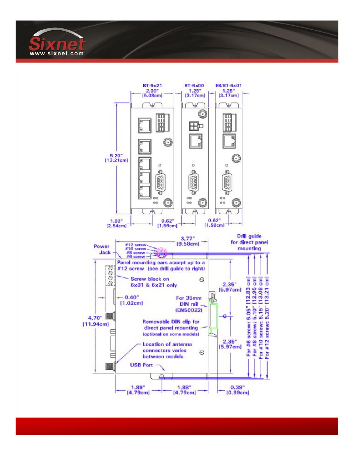
1.3.3 Mechanical specifications BT-6000
IndustrialPro™ and MobilityPro™ Gateway
User's Guide
Copyright © 2010 Sixnet LLC. All rights reserved.
15
1.11 –November 2, 2011
1.3.4 Power specifications and consumption
Power is supplied to the modem via:
4-pin Molex connector for the BT-6x00 and BT-5x00v2 models
4-pin screw terminal for the BT-6x01, BT-6x01EB and BT-6x21 models
DC 2.5mm barrel plug for all BT-6000 models
Power over Ethernet for all BT-6x01EB models
1.3.4.1 4-pin Molex Connector (BT-5000v2)
Power is supplied to the modem via the 4-pin Molex connector on the rear panel for BT-5x00 v2 models. The pins are
described as follows:
Table 3 - 4-pin Molex connector (BT-5000v2)
O3 IGN
GND POS
Power connector
(facing modem)
Pin
Name
Description
1
GND
Ground
2
POS
Power supply input (8 to 30 VDC)
3
IGN
Ignition sense input (switches modem on or off)
4
O3
Digital Output 3
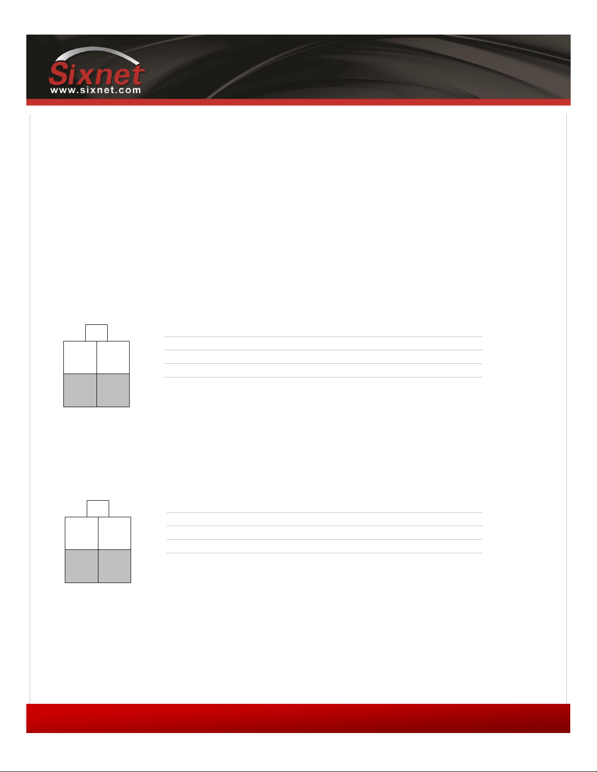
1.3.4.2 4-pin Molex Connector (BT-6x00)
Power is supplied to the modem via the 4-pin Molex connector on the front panel for the BT-6x00 models. The pins are
described as follows:
Table 4 - 4-pin Molex connector (BT-6x00)
OUT IN
GND POS
Power connector
(facing modem)
Pin
Name
Description
1
GND
Ground
2
POS
Power supply input (8 to 30 VDC)
3
IN
Digital and analog input
4
OUT
Digital Output
IndustrialPro™ and MobilityPro™ Gateway
User's Guide
Copyright © 2010 Sixnet LLC. All rights reserved.
16
1.11 –November 2, 2011
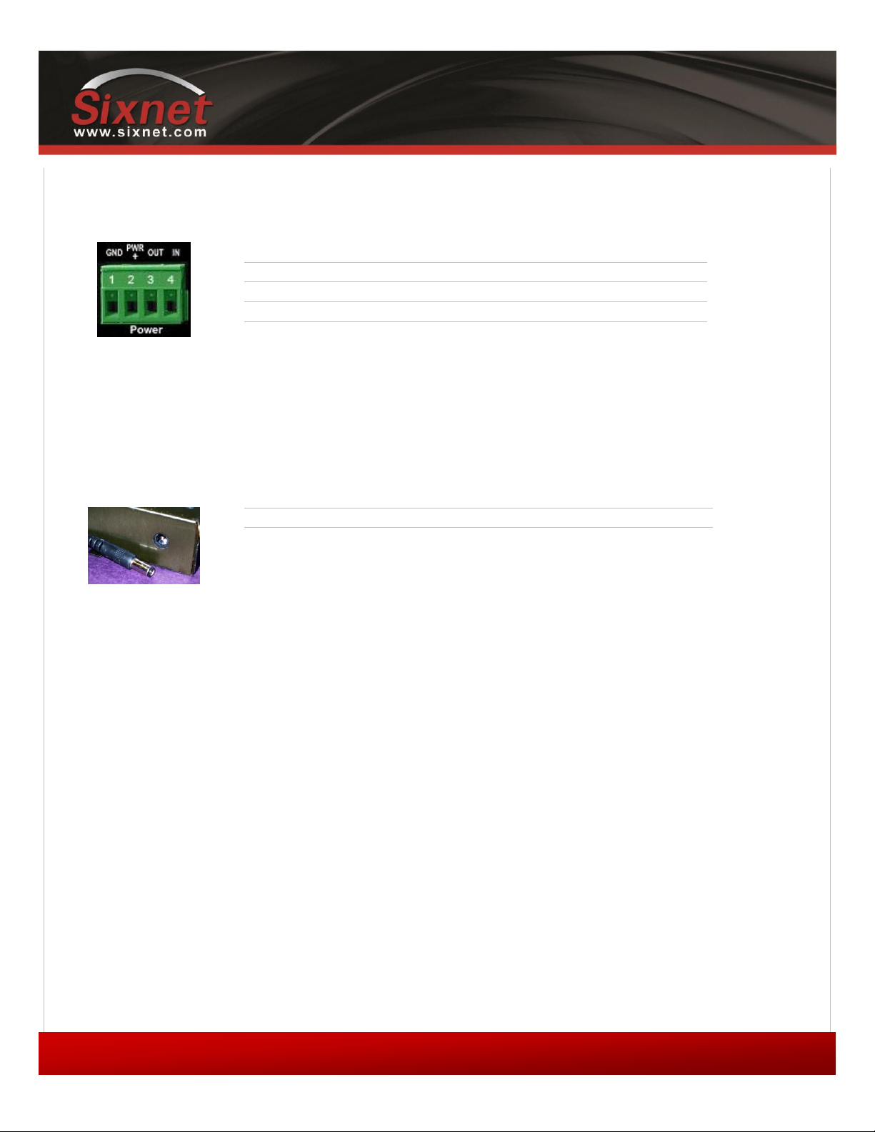
1.3.4.3 4-pin Screw Terminal (BT-6xx1)
Power is supplied to the modem via the 4-pin Screw Terminal on the front panel for the BT-6xx1 models. The pins are
described as follows:
Table 5 - 4-pin screw terminal (BT-6xx1)
Power connector
(facing front)
Pin
Name
Description
1
GND
Ground
2
PWR+
Power supply input (8 to 30 VDC)
3
OUT
Digital output
4
IN
Digital and analog input
1.3.4.4 DC 2.5mm Barrel Adapter
Power is supplied to the modem via the barrel adapter on the left side of all BT-6000 series modems. The contacts are
described as follows:
Table 6 –DC 2.5mm Barrel adapter (BT-6000)
Power connector
(facing left side)
Pin
Name
Description
Sleeve
GND
Ground
Tip
PWR+
Power supply input (8 to 30 VDC)
WARNING:
DC 2.5mm Barrel Adapter shall not be used in hazardous locations.

IndustrialPro™ and MobilityPro™ Gateway
User's Guide
Copyright © 2010 Sixnet LLC. All rights reserved.
17
1.11 –November 2, 2011
1.3.4.5 Power specification
Power input to the modem is protected against reverse polarity and over-voltage.
The modem’s power consumption is as follows:
Table 7 –Power consumption
Model
Draw in mA (at 12 VDC)
Standby
Transmitting
Peaks
BT-5600v2
123
221
452
BT-5800v2
123
328
810
BT-6401
115
246
417
BT-6421
229
360
531
BT-660x
115
213
444
BT-6621
249
347
578
BT-6800
115
320
802
BT-680x
115
320
802
BT-6821
249
454
936
Wiring instructions are provided in the Hardware Installation section.
All modems are equipped with protection for reversed polarity and power surges over 33 volts. The modems are
equipped with an internal 3 Amp fuse. When using the 4 pin Molex connector / power accessory cable supplied by
BlueTree Wireless, an extra 2 Amp fuse is also included (5600v2, 5800v2).
IndustrialPro™ and MobilityPro™ Gateway
User's Guide
Copyright © 2010 Sixnet LLC. All rights reserved.
18
1.11 –November 2, 2011
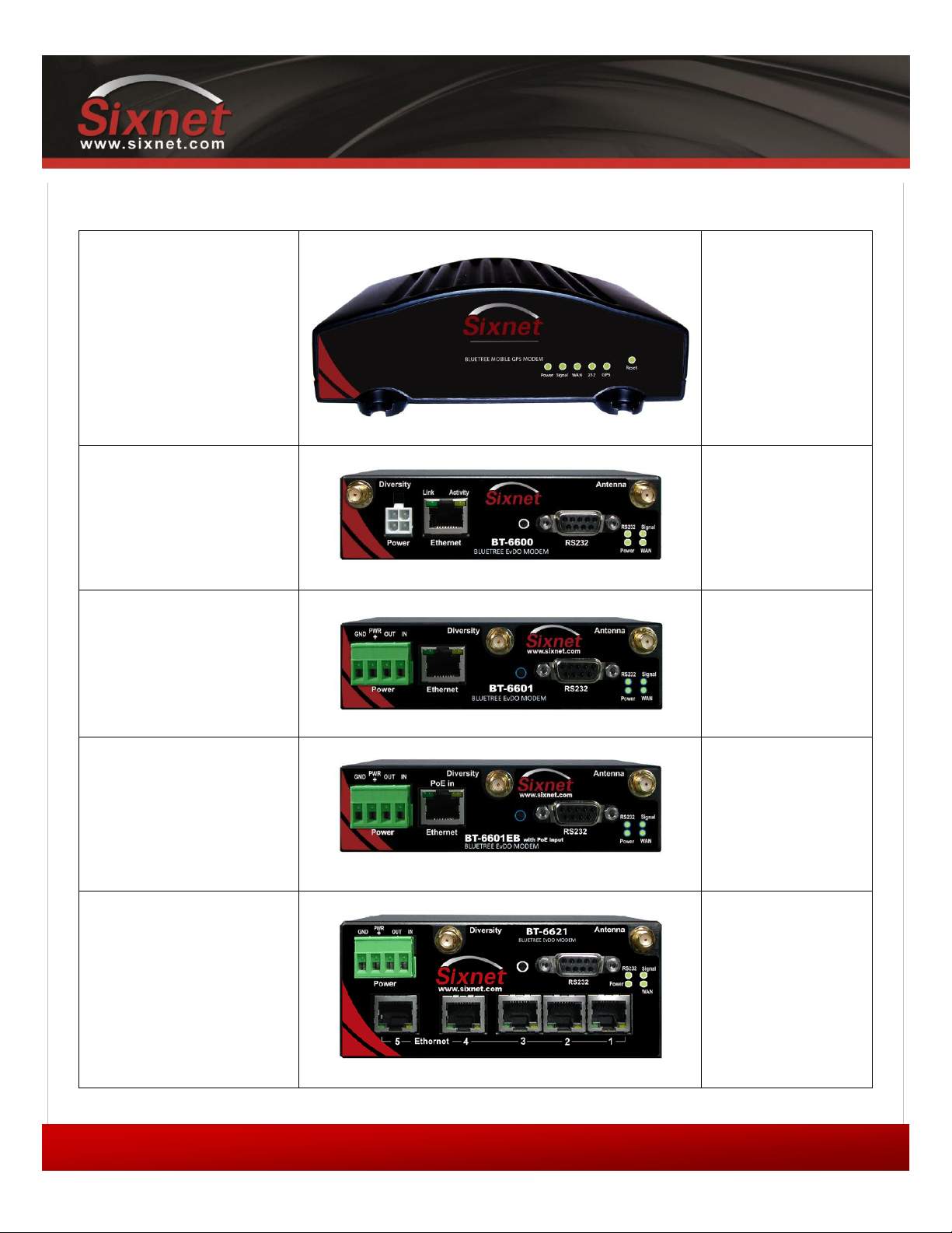
1.3.5 Modem views (Sixnet labels)
Standalone GPS
With Wi-Fi(5x30 only)
BT-5xx0v2
BT-5600v2
BT-5800v2
BT-5630
BT-5830
4-pin power connector
BT-6x00
BT-6600
BT-6800
Screw-block power connector
BT-6x01
BT-6401*
BT-6601
BT-6801
Screw-block power connector
&
PoE power input
BT-6x01EB
BT-6401EB*
BT-6601EB
BT-6801EB
Ethernet Switch
BT-6x21
BT-6421*
BT-6621
BT-6821
The BT-64xx series modems are not equipped with a diversity antenna connector
IndustrialPro™ and MobilityPro™ Gateway
User's Guide
Copyright © 2010 Sixnet LLC. All rights reserved.
19
1.11 –November 2, 2011
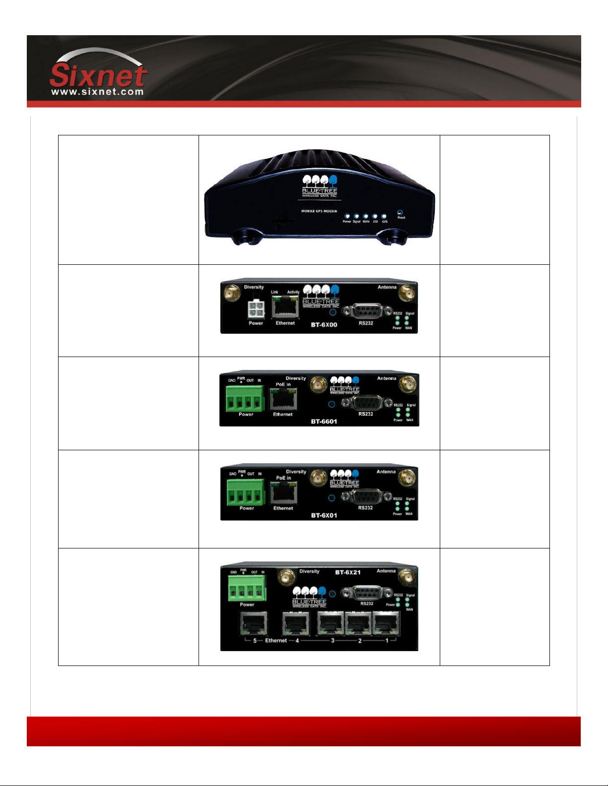
1.3.6 Modem views (BlueTree labels)
Standalone GPS
BT-5x00v2
BT-5600v2
BT-5800v2
4-pin power connector
BT-6x00
BT-6600
BT-6800
Screw-block power connector
BT-6x01
BT-6401*
BT-6601
BT-6801
Screw-block power connector
&
PoE power input
BT-6x01EB
BT-6401EB*
BT-6601EB
BT-6801EB
Ethernet Switch
BT-6x21
BT-6421*
BT-6621
BT-6821
The BT-64xx series modems are not equipped with a diversity antenna connector

IndustrialPro™ and MobilityPro™ Gateway
User's Guide
Copyright © 2010 Sixnet LLC. All rights reserved.
20
1.11 –November 2, 2011
1.3.7 Indicators Lights (LED)
Table 8 –LEDs
LED
Status
Corresponding State
Power
OFF
Modem is powered off
ON
Modem is powered on
FLASH
Firmware error
Signal
OFF
No signal available or signal strength is below -100 dBm
ON
Excellent signal strength = greater than -69 dBm
FLASH
Fast: Every 300ms = -79 to -70 dBm
Medium: Every 600ms = -89 to -80 dBm
Slow: Every 1200ms = -99 to -90 dBm
WAN
OFF
Cellular connection is not established
ON
Cellular connection is established - no network data activity
FLASH
Cellular connection is established - with network data activity
RS232
OFF
Serial connection is not established
ON
Serial connection is established - no data activity with host
FLASH
Serial connection is established - with data activity with host
GPS
(BT-5x00v2)
OFF
No position fix available
ON
Position fix available
1.3.8 Data Interface Specifications: Serial, Ethernet & USB
1.3.8.1 Ethernet Port
The modem's 10/100Mbps Ethernet port is compliant with the EIA-568 standard. The modem’s ports are autosensing so
they can be used with either a straight or crossover RJ45 cable to connect to host ports.
The BT-6x21 features a 5-port Ethernet switch allowing connectivity to multiple local devices.
This manual suits for next models
1
Table of contents
Other Sixnet Modem manuals


