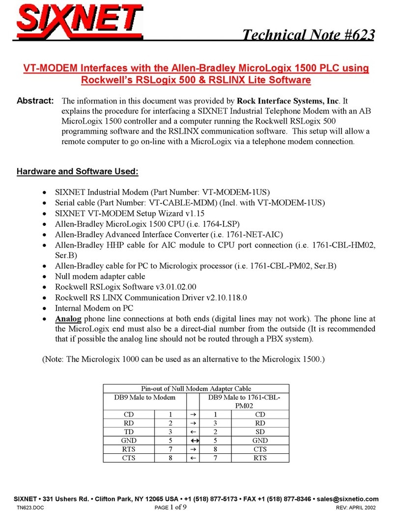
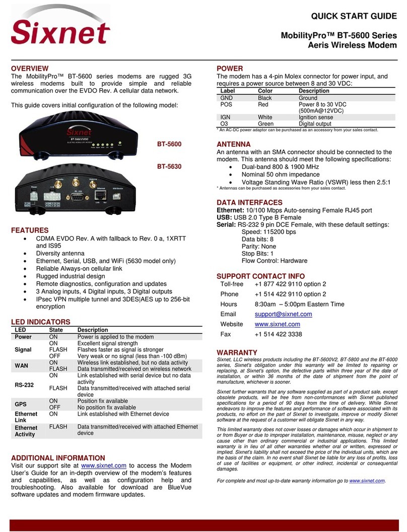
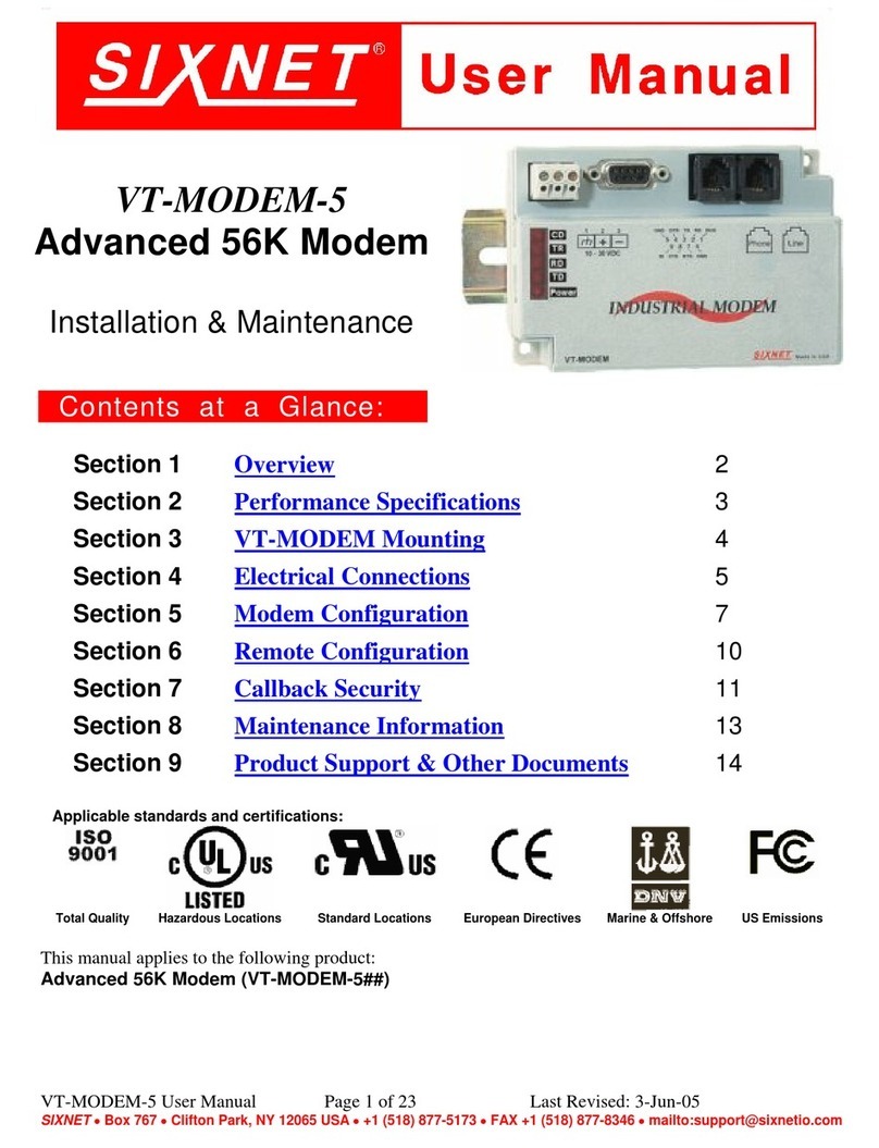
Sixnet BT-5600v2 User manual

Industrial Wireless Modems
BT-5600v2 BT-5800v2
BT-6000 series
User's Guide
1.8
March 30, 2010

Industrial Wireless Modems
User's Guide
Copyright © 2010 Sixnet LLC. All rights reserved.
2
1.8 – March 30, 2010
Nopartofthispublication,oranysoftwareincludedwithit,maybereproduced,storedinaretrievalsystem,or
transmittedinanyformorbyanymeans,includingphotocopying,electronic,mechanical,recordingorotherwise,
withoutthepriorwrittenpermissionofthecopyrightholder.
Sixnet,LLC(Sixnet)providesthisdocumentasis,withoutwarrantyofanykindeitherexpressedorimpliedincluding,but
notlimitedto,theimpliedwarrantiesofmerchantabilityandfitnessforaparticularpurpose.Sixnetmaymakechanges
ofimprovementsintheequipment,software,orspecificationsdescribedinthisdocumentatanytimeandwithout
notice.Thesechangesmaybeincorporatedinnewreleasesofthisdocument.
Thisdocumentmaycontaintechnicalinaccuraciesortypographicalerrors.Sixnetanditssubsidiarieswaiveresponsibility
foranylabor,materials,orcostsincurredbyanypersonorpartyasaresultofusingthisdocument.
Sixnetandanyofitssubsidiariesorotheraffiliatesshallnotbeliableforanydamages(including,butnotlimitedto,
consequential,indirectorincidental,specialdamages,orlossofprofitsordata)eveniftheywereforeseeableandSixnet
hasbeeninformedoftheirpotentialoccurrencearisingoutoforinconnectionwiththisdocumentoritsuse.
ComputerSoftwareCopyrights
TheproductsdescribedinthismanualincludecopyrightedSixnetcomputerprogramsstoredinsemi‐conductor
memoriesorothermedia.LawsinCanada,theUnitedStatesandothercountriespreserveforSixnetcertainrightsfor
copyrightedcomputerprograms,includingtheexclusiverighttocopyorreproduceinanyformthecopyrighted
computerprogram.Accordingly,anycopyrightedSixnetcomputerprogramscontainedintheSixnetproductsdescribed
inthismanualmaynotbecopiedwithouttheexpresswrittenpermissionofSixnet.
Furthermore,thepurchaseofSixnetproductsshallnotbedeemedtogranteitherdirectlyorbyimplication,estoppels,
orotherwise,anylicenseunderthecopyrights,patentsorpatentapplicationsofSixnet,exceptforthenormalnon‐
exclusive,royalty‐freelicensetousethatarisesbyoperationoflawsinthesaleofaproduct.
Sixnet,LLC
2425,46thAvenue,
Lachine,QuebecH8T3C9,Canada
Phone:1‐514‐422‐9110option2
TollFree:1‐877‐422‐9110option2
Fax:1‐514‐422‐3338
Web:www.sixnet.com

Industrial Wireless Modems
User's Guide
Copyright © 2010 Sixnet LLC. All rights reserved.
3
1.8 – March 30, 2010
Liability Notice
Whileeveryefforthasbeenmadetoachievetechnicalaccuracy,informationinthisdocumentissubjecttochange
withoutnoticeanddoesnotrepresentacommitmentonthepartofBlueTreeWirelessData,Inc.,oranyofitssubsidies,
affiliates,agents,licensors,orresellers.Therearenowarranties,expressorimplied,withrespecttothecontentofthis
document.
Declaration of Conformity
ThedevicecomplieswithPart15ofFCCrulesandwithICES‐003ofIndustryCanadaRules.Operationissubjecttothe
followingtwoconditions:
•Thisdevicemaynotcauseharmfulinterference
•Thisdevicemustacceptanyinterferencereceived,includinginterferencethatmaycauseundesired
operation
Thisequipmentgeneratesusesandcanradiateradiofrequencyenergyand,ifnotinstalledandusedinaccordancewith
themanufacturer'sinstructions,maycauseinterferenceharmfultoradiocommunications.However,thereisno
guaranteethatinterferencewillnotoccurinaparticularinstallation.Ifthisequipmentdoescauseharmfulinterference
toradioortelevisionreception,whichcanbedeterminedbyturningtheequipmentoffandon,theuserisencouraged
totrytocorrecttheinterferencebyoneormoreofthefollowingmeasures:
Reorient or relocate the receiving antenna
Increase the separation between the equipment and receiver
Connect the equipment into an outlet on a circuit different from that to which the receiver is
connected
Consultthedealeroranexperiencedradio/TVtechnicianforhelp.
WARNING
TocomplywithRSS‐102HealthCanadaSafetyCode6,theantenna(s)usedforthistransmittermustbeinstalledto
provideaseparationdistanceofatleast10cmfromallpersonsandmustnotbeco‐locatedoroperatinginconjunction
withanyotherantennaortransmitter.UsersandInstallersmustbeprovidedwithantennainstallationinstructionand
transmitteroperatingconditionsforsatisfyingRFexposurecompliance.
BT‐6000seriesbarrelpowerconnectorshallnotbeusedinhazardouslocations.

Industrial Wireless Modems
User's Guide
Copyright © 2010 Sixnet LLC. All rights reserved.
4
1.8 – March 30, 2010
Change history
VersionDateDescription
1.8March30,2010Changedocumentformat

Industrial Wireless Modems
User's Guide
Copyright © 2010 Sixnet LLC. All rights reserved.
5
1.8 – March 30, 2010
Table of content
1ProductOverview ................................................................................................................................................. 8
1.1 Introduction........................................................................................................................................................... 8
1.2 Modemfeatures .................................................................................................................................................... 9
1.3 Specifications....................................................................................................................................................... 11
2BlueVueDeviceManager(BVDM) ....................................................................................................................... 21
2.1 Connectingtothemodem................................................................................................................................... 22
2.2 Softwareoverview............................................................................................................................................... 24
3ATCommands ..................................................................................................................................................... 25
3.1 Access .................................................................................................................................................................. 25
4Activation&WANSetup ..................................................................................................................................... 26
4.1 Activation(CDMAmodemsonly) ........................................................................................................................ 26
4.2 WANSetup .......................................................................................................................................................... 27
5LANSetup ........................................................................................................................................................... 30
5.1 EthernetandUSBLAN ......................................................................................................................................... 30
5.2 LANconfiguration................................................................................................................................................ 30
5.3 DHCPserver ......................................................................................................................................................... 31
5.4 Dial‐upNetworking(DUN)overserial ................................................................................................................. 31
6IPNetworkingFeatures ....................................................................................................................................... 33
6.1 Port‐forwarding ................................................................................................................................................... 33
6.2 DMZ ..................................................................................................................................................................... 34
6.3 IPpass‐through.................................................................................................................................................... 35
6.4 DynamicIPregistration ....................................................................................................................................... 36
6.5 IPSecurity(IPSEC)................................................................................................................................................ 37
6.6 AccessControlList(ACL)...................................................................................................................................... 37
6.7 Passwordprotection............................................................................................................................................ 37
7SerialIP............................................................................................................................................................... 39
8GPS ..................................................................................................................................................................... 40
8.1 GPSprotocols ...................................................................................................................................................... 41
8.2 Storeandforward................................................................................................................................................ 41
8.3 Odometer ............................................................................................................................................................ 42
8.4 ConfiguringthemodemforGPSreporting.......................................................................................................... 42
9I/OManagement................................................................................................................................................. 43
9.1 DigitalOutputcontrol.......................................................................................................................................... 43
9.2 DigitalInputstatequery ...................................................................................................................................... 43
9.3 AnalogInputvaluequery .................................................................................................................................... 44
10 EventReporting ............................................................................................................................................. 45
10.1 Events .................................................................................................................................................................. 45
10.2 Actions ................................................................................................................................................................. 45
10.3 Reports ................................................................................................................................................................ 46
11 HardwareInstallation .................................................................................................................................... 47
11.1 MountingtheBT‐5x00v2seriesmodem ............................................................................................................. 47
11.2 MountingtheBT‐6000seriesmodem................................................................................................................. 47

Industrial Wireless Modems
User's Guide
Copyright © 2010 Sixnet LLC. All rights reserved.
6
1.8 – March 30, 2010
11.3 Cellularantenna................................................................................................................................................... 47
11.4 Ethernetcable ..................................................................................................................................................... 49
11.5 USBcable ............................................................................................................................................................. 49
11.6 Serialcable........................................................................................................................................................... 49
11.7 Powersource ....................................................................................................................................................... 49
12 Appendixes.................................................................................................................................................... 51
12.1 BlueVueDeviceManagerTroubleshooting ......................................................................................................... 51
12.2 ActivationTroubleshooting ................................................................................................................................. 55
12.3 Troubleshooting .................................................................................................................................................. 58
12.4 FirmwareUpgrades ............................................................................................................................................. 62
12.5 SendingATCommands........................................................................................................................................ 64
12.6 Dial‐UpNetworkinginWindows .........................................................................................................................66
12.7 Warranty.............................................................................................................................................................. 68
12.8 CustomerSupport ............................................................................................................................................... 69

Industrial Wireless Modems
User's Guide
Copyright © 2010 Sixnet LLC. All rights reserved.
7
1.8 – March 30, 2010
Figures
Figure1‐Routermode ........................................................................................................................................................... 8
Figure2‐IPpass‐throughmode ............................................................................................................................................. 9
Figure3–Serialconnector(lookingatbackofmodem) ...................................................................................................... 20
Figure4–Thedifferentwaystoconnecttoamodem......................................................................................................... 22
Figure5–Connectingtoaremotemodem.......................................................................................................................... 23
Figure6–Confirmingthesuccessofactivation ................................................................................................................... 27
Figure7–Editingtheaccountinformation .......................................................................................................................... 28
Figure8–Testingtheconnection......................................................................................................................................... 29
Figure9–DefaultLANIPconfiguration................................................................................................................................ 30
Figure10–SamplemodemconfigurationforcommunicatingwithadevicethathastheIP10.127.0.17 ......................... 31
Figure11–Port‐forwardingentries...................................................................................................................................... 34
Figure12–EnablingDMZ ..................................................................................................................................................... 35
Figure13–EnablingIPpassthrough..................................................................................................................................... 35
Figure14–EnablingDynamicIPRegistration ...................................................................................................................... 37
Figure15–Enablingpasswordprotection ........................................................................................................................... 38
Figure16–SerialIP............................................................................................................................................................... 39
Figure17–GPSconfigurationscreen ................................................................................................................................... 40
Figure18–Modemwithgoodsignalstrength ..................................................................................................................... 55
Figure19–PhonenumberbeingdisplayedontheModemDiagnosticscreenafteractivation ......................................... 56
Figure20–WANIPbeingdisplayedafterthemodemsuccessfullyconnectstothecellularnetwork ............................... 57
Figure21–Upgradingthefirmware..................................................................................................................................... 63
Figure22–CreatinganewconnectioninWindowsXP ....................................................................................................... 66
Tables
Table1–Modemfeatures...................................................................................................................................................... 9
Table2–Generalspecifications ........................................................................................................................................... 11
Table3‐4‐pinMolexconnector(BT‐5000v2) ...................................................................................................................... 15
Table4‐4‐pinMolexconnector(BT‐6x00) .......................................................................................................................... 15
Table5‐4‐pinscrewterminal(BT‐6xx1) .............................................................................................................................. 16
Table6–DC2.5mmBarreladapter(BT‐6000) ..................................................................................................................... 16
Table7–Powerconsumption .............................................................................................................................................. 17
Table8–LEDs ....................................................................................................................................................................... 19
Table9–Resetbuttonfunctions .......................................................................................................................................... 20
Table10–DHCPIPassignment ............................................................................................................................................ 30
Table11–NMEAmessagesinformation .............................................................................................................................. 41
Table12–dBlossper100feetofcabletype ....................................................................................................................... 47

Industrial Wireless Modems
User's Guide
Copyright © 2010 Sixnet LLC. All rights reserved.
8
1.8 – March 30, 2010
1ProductOverview
1.1 Introduction
TheBlueTree5000v2and6000seriesmodemsareruggedcellularmodemsbuilttoprovidesimpleandreliable
communicationoveraCDMAorGSMcellulardatanetworks.TheyaretypicallyusedinapplicationssuchasPublic
Safety,Transportation,VehicleTracking,Telemetry,SCADA,Remote/TemporaryOffices,LandlineReplacement, and
WANbackup/BusinessContinuity.
Themodelscoveredbythisdocumentare:
TypeCDMAEvDO.AGSMEDGEGSMHSPA
StandaloneGPSBT‐5600v2 BT‐5800v2
4‐pinpowerconnectorBT‐6600 BT‐6800
Screw‐blockpowerconnectorBT‐6601BT‐6401BT‐6801
PoEpowerinputBT‐6601EBBT‐6401EBBT‐6801EB
EthernetSwitchBT‐6621BT‐6421BT‐6821
Themodemsupportstwooperationalmodes:routermode,andIPpass‐throughmode.
1.1.1 Routermode
InRoutermode,whichisthedefaultmode,themodemmanageslocalandwirelessconnectionsindependently,andis
capableofroutingdatapacketsbackandforthbetweenthetwo.
Figure 1 - Router mode

Industrial Wireless Modems
User's Guide
Copyright © 2010 Sixnet LLC. All rights reserved.
9
1.8 – March 30, 2010
Themodemmanagestwoconnectionsatthesametime,thusactingasagateway/router:
CellularWANconnection: This is the Wide Area Network connection to the cellular
network/Internet. The modem can be configured to automatically and autonomously
establish a packet data connection to the cellular carrier and acquire a WAN IP address.
LANconnection: This is the local connection between the modem and any device attached to
its Serial / Ethernet / USB ports. In the case of Ethernet and USB, the modem acts as a
DHCP server and assigns a private LAN IP address to the attached device.
ThemodemthenroutespacketsbackandforthbetweenitsWANandLANconnections,andinturnallowsthelocally
attacheddevicetocommunicatewithcomputersordevicesataremotelocation.
1.1.2 IPpass‐throughmode
InIPpass‐throughmode,themodemassignsitsWANIPaddressdirectlytotheattachedhost,thusbecomingafully
transparentactorinthecommunicationprocess.ThemodemremainsreachablethroughitsreservedTCPandUDPports
sothatremoteadministrationandconfigurationisstillpossible.NotethatthismodeallowsonlyoneIPaddresstobe
assignedtothefirstconnecteddeviceviaDHCP(ThisconfigurationisnotrecommendedforBT‐6x21).
Figure 2 - IP pass-through mode
1.2 Modemfeatures
Table 1 – Modem features
3 different data
connection interfaces Serial/RS-232/COM, Ethernet, and USB
Ethernet switch Available on the BT-6x21 models only. These models have
an embedded 5-port Ethernet switch.

Industrial Wireless Modems
User's Guide
Copyright © 2010 Sixnet LLC. All rights reserved.
10
1.8 – March 30, 2010
Power-over-Ethernet
Models ending in EB (BT-6x01EB) are models with built in
power sourcing. Power-over-Ethernet compatible devices
can be powered simply by connecting it to the modem’s
Ethernet port.
Autonomous &
persistent connection
management
Fully integrated TCP/IP protocols allow the modem to
connect autonomously to the packet network (Internet). This
feature enables capabilities such as: in-call diagnostic,
Serial-IP, stand-alone GPS, remote configuration and remote
firmware upgrades.
DHCP server The modem’s DHCP server allows easy administration and
setup of the local network by automating IP address
assignment
IP pass-through
The modem can assign its WAN IP address to the attached
host, thus disabling the DHCP server’s Network Address
Translation. Even when performing pass-through, the
modem remains reachable for remote administration
through its reserved TCP ports.
IP security The modem can be configured with up to 10 IPSEC tunnels
for increased security in communications.
In-call diagnostic The user can get modem status information while in a data
call, without interrupting the data session
Serial IP
The modem can provide a reliable means of communication
with serial-only legacy devices. It can encapsulate data
coming from the serial port into a TCP or UDP packet and
send it to a remote server on the packet network or
Internet. It can decapsulate IP packets coming from the
network and send raw data to the serial port.
Remote configuration The modem can be remotely configured or diagnosed using
BlueVue Device Manager or a terminal session
Remote firmware
upgrade The modem’s firmware can be remotely upgraded using
BlueVue Device Manager software
Password protection The modem’s configuration can be protected from tampering
by requesting the user to enter a password before the
existing modem configuration can be viewed or modified
Integrated GPS receiver
BT-5000v2 models include a GPS receiver for Automatic
Vehicle Location (AVL). The modem can report this
positioning data locally to any of the local data interfaces
(serial, Ethernet, or Ethernet-over-USB), and/or remotely to
a predefined server (see stand-alone).
Standalone GPS BT-5000v2 modems can be used for remote asset tracking
by sending GPS data to a remote server without the need for
a client application or computer connected to the modem.

Industrial Wireless Modems
User's Guide
Copyright © 2010 Sixnet LLC. All rights reserved.
11
1.8 – March 30, 2010
Store and forward
If a unit loses its connection to the cellular network, the
event data being collected from I/O, GPS and other sources
will be stored in memory and automatically forwarded when
the connection is reestablished. This is available when using
TCP or UDP with ACK.
Inputs and outputs
Sensors can be connected to the I/O ports of the modem.
Depending on models, the modem is capable of monitoring
up to four digital inputs for any change in state, and up to
three analog inputs for changes in gradient data sources.
The modem also has up to three digital outputs that can be
used to remotely trigger relays.
The inputs and outputs can be used with the event reporting
protocol to allow automatic reports and triggers.
Event reporting
The modem can send a report to up to 10 destinations when
a user-defined event is triggered. Up to 30 events can be
defined based on I/O signals, GPS data, RF status. The
modem has an embedded event reporting protocol that
automatically formats the messages reported to the remote
server.
Mobile Originated
Management
The modem can connect to a remote server and perform
management actions (firmware upgrade, configuration
changes …). This feature uses Event Reporting.
Partner apps The modem can host partner applications used for example
to report cellular traffic usage, vehicle diagnostics, alarms, …
1.3 Specifications
1.3.1 Generalspecifications
Table 2 – General specifications
Wireless interfaces
CDMA EvDO.A models
Dual-band CDMA2000 EVDO Rev. A (with diversity)
Backward compatible with 1xRTT and IS95
GSM EDGE Models
Quad-band 850/900/1800/1900 GSM
Backward compatible with Quad-band GPRS/UMTS
GSM HSPA Models
Quad-band 800/850/1900/2100 MHz WCDMA (with diversity)
HSDPA/HSUPA/HSPA
Backward compatible with GPRS/EDGE/UMTS
Peak data rates Download: CDMA – 3.1Mbps / EDGE – 384 kbps / HSPA - 7 Mbps
Upload: CDMA - 1.8 Mbps / EDGE – 120 kbps / HSPA - 5.76 Mbps
Serial interface 1x RS-232 Serial DB9 115200bps

Industrial Wireless Modems
User's Guide
Copyright © 2010 Sixnet LLC. All rights reserved.
12
1.8 – March 30, 2010
USB interface BT-5000v2 series: 1x USB 2.0 type B
BT-6000 series: 1x USB 2.0 mini B
LED indicators Power, WAN, Signal, RS232, GPS, Ethernet Link & Activity
Dimensions BT-6x0x: 120 x 96 x 32 mm (4.7 x 3.77 x 1.25"), 453g (1.0 lb)
BT-6x21: 120 x 96 x 51 mm (4.7 x 3.77 x 2.00"), 500g (1.1 lb)
BT-5x00v2: 159 x 127 x 53 mm (6.26 x 5.00 x 2.09”), 500g (1.1 lb)
Power Input 8 - 30 VDC (12 VDC nominal), Power over Ethernet on BT-6x01EB
Power consumption See Table 6
Environmental
BT-5000v2 series
Operating Temp: -40 to +85°C (-40 to 185°F)
Shock & Vibration: MIL-STD 810F/202G
Humidity: 5 to 95% non-condensing
BT-6000 series
Operating Temp: -40 to +75°C (-40 to 167°F)
Shock & Vibration: IEC68-2-27, IEC68-2-6, MIL-STD 810F/202G
Humidity: 5 to 95% non-condensing
Certification
Hazardous Locations - Class I, Div. 2, Groups A,B,C,D, UL1604
Electrical Safety - UL508/CSA22.2/14 (CUL)
EMC- FCC, part 15 and Industry Canada, ICES-003
PTCRB (GSM), CE, R&TTE

Industrial Wireless Modems
User's Guide
Copyright © 2010 Sixnet LLC. All rights reserved.
13
1.8 – March 30, 2010
1.3.2 MechanicalspecificationsBT‐5x00v2

Industrial Wireless Modems
User's Guide
Copyright © 2010 Sixnet LLC. All rights reserved.
14
1.8 – March 30, 2010
1.3.3 MechanicalspecificationsBT‐6000

Industrial Wireless Modems
User's Guide
Copyright © 2010 Sixnet LLC. All rights reserved.
15
1.8 – March 30, 2010
1.3.4 Powerspecificationsandconsumption
Powerissuppliedtothemodemvia:
4-pin Molex connector for the BT-6x00 and BT-5x00v2 models
4-pin screw terminal for the BT-6x01, BT-6x01EB and BT-6x21 models
DC 2.5mm barrel plug for all BT-6000 models
Power over Ethernet for all BT-6x01EB models
1.3.4.1 4‐pinMolexConnector(BT‐5000v2)
Powerissuppliedtothemodemviathe4‐pinMolexconnectorontherearpanelforBT‐5x00v2models.Thepinsare
describedasfollows:
Table3‐4‐pinMolexconnector(BT‐5000v2)
PinNameDescription
1GNDGround
2POSPowersupplyinput(8to30VDC)
3IGNIgnitionsenseinput(switchesmodemonoroff)
Powerconnector
(facingmodem)
4O3DigitalOutput3
1.3.4.2 4‐pinMolexConnector(BT‐6x00)
Powerissuppliedtothemodemviathe4‐pinMolexconnectoronthefrontpanelfortheBT‐6x00models.Thepinsare
describedasfollows:
Table4‐4‐pinMolexconnector(BT‐6x00)
PinNameDescription
1GNDGround
2POSPowersupplyinput(8to30VDC)
3INDigitalandanaloginput
OUT IN
GND POS
Powerconnector
(facingmodem)
4OUTDigitalOutput

Industrial Wireless Modems
User's Guide
Copyright © 2010 Sixnet LLC. All rights reserved.
16
1.8 – March 30, 2010
1.3.4.3 4‐pinScrewTerminal(BT‐6xx1)
Powerissuppliedtothemodemviathe4‐pinScrewTerminalonthefrontpanelfortheBT‐6xx1models.Thepinsare
describedasfollows:
Table5‐4‐pinscrewterminal(BT‐6xx1)
PinNameDescription
1GNDGround
2PWR+Powersupplyinput(8to30VDC)
3OUTDigitaloutput
Powerconnector
(facingfront)
4INDigitalandanaloginput
1.3.4.4 DC2.5mmBarrelAdapter
PowerissuppliedtothemodemviathebarreladapterontheleftsideofallBT‐6000seriesmodems.Thecontactsare
describedasfollows:
Table6–DC2.5mmBarreladapter(BT‐6000)
PinNameDescription
SleeveGNDGround
Powerconnector
(facingleftside)
TipPWR+Powersupplyinput(8to30VDC)
WARNING:
DC2.5mmBarrelAdaptershallnotbeusedinhazardouslocations.

Industrial Wireless Modems
User's Guide
Copyright © 2010 Sixnet LLC. All rights reserved.
17
1.8 – March 30, 2010
1.3.4.5 Powerspecification
Powerinputtothemodemisprotectedagainstreversepolarityandover‐voltage.
Themodem’spowerconsumptionisasfollows:
Table7–Powerconsumption
DrawinmA(at12VDC)
Model
Standby Transmitting Peaks
BT-5600v2 123 221 452
BT-5800v2 123 328 810
BT-6401 115 246 417
BT-6421 229 360 531
BT-660x 115 213 444
BT-6621 249 347 578
BT-6800 115 320 802
BT-680x 115 320 802
BT-6821 249 454 936
WiringinstructionsareprovidedintheHardwareInstallationsection.
Allmodemsareequippedwithprotectionforreversedpolarityandpowersurgesover33volts.Themodemsare
equippedwithaninternal3Ampfuse.Whenusingthe4pinMolexconnector/poweraccessorycablesuppliedby
BlueTreeWireless,anextra2Ampfuseisalsoincluded(5600v2,5800v2).

Industrial Wireless Modems
User's Guide
Copyright © 2010 Sixnet LLC. All rights reserved.
18
1.8 – March 30, 2010
1.3.5 Modemviews
StandaloneGPS
BT‐5x00v2
•BT‐5600v2
•BT‐5800v2
4‐pinpowerconnector
BT‐6x00
•BT‐6600
•BT‐6800
Screw‐blockpowerconnector
BT‐6x01
•BT‐6401*
•BT‐6601
•BT‐6801
Screw‐blockpowerconnector
&
PoEpowerinput
BT‐6x01EB
•BT‐6401EB*
•BT‐6601EB
•BT‐6801EB
EthernetSwitch
BT‐6x21
•BT‐6421*
•BT‐6621
•BT‐6821
∗TheBT‐64xxseriesmodemsarenotequippedwithadiversityantennaconnector

Industrial Wireless Modems
User's Guide
Copyright © 2010 Sixnet LLC. All rights reserved.
19
1.8 – March 30, 2010
1.3.6 IndicatorsLights(LED)
Table 8 – LEDs
LED Status Corresponding State
OFF Modem is powered off
ON Modem is powered on
Power
FLASH Firmware error
OFF No signal available or signal strength is below -100 dBm
ON Excellent signal strength = greater than -69 dBm
Fast: Every 300ms = -79 to -70 dBm
Medium: Every 600ms = -89 to -80 dBm
Signal
FLASH
Slow: Every 1200ms = -99 to -90 dBm
OFF Cellular connection is not established
ON Cellular connection is established - no network data activity
WAN
FLASH Cellular connection is established - with network data activity
OFF Serial connection is not established
ON Serial connection is established - no data activity with host
RS232
FLASH Serial connection is established - with data activity with host
OFFNopositionfixavailable
GPS
(BT‐5x00v2)ONPositionfixavailable
1.3.7 DataInterfaceSpecifications:Serial,Ethernet&USB
1.3.7.1 EthernetPort
Themodem's10/100MbpsEthernetportiscompliantwiththeEIA‐568standard.Themodem’sportsareautosensingso
theycanbeusedwitheitherastraightorcrossoverRJ45cabletoconnecttohostports.
TheBT‐6x21featuresa5‐portEthernetswitchallowingconnectivitytomultiplelocaldevices.

Industrial Wireless Modems
User's Guide
Copyright © 2010 Sixnet LLC. All rights reserved.
20
1.8 – March 30, 2010
1.3.7.2 USBDevicePort
ThisisaUSB2.0DeviceinterfaceonaTypeB(BT‐5x00v2)orMiniB(BT‐6xxx)connector.ItoffersEthernet‐over‐USB
functionalityusingtheRNDISdriverforWindowsXPandWindowsVistaOperatingsystemsonly.TheBlueTreeRNDIS
drivermustbeinstalledbeforetheUSBinterfacecanbeused.ThedriverisautomaticallyinstalledwithBlueTreeDevice
Manageroryoucanobtainthedriveratwww.sixnet.comandinstallitmanually.
1.3.7.3 SerialPort(DB9)
Themodem’sserialportisanRS232DCE,compliantwithEIA‐232standard.TheconnectorusedisDB9femaleandis
shownintheillustrationbelow.
Figure 3 – Serial connector (looking at back of modem)
Forfurtherserialwiringinformation,refertotheHardwareInstallationsection.
1.3.8 RESETbuttonfunctions
Table 9 – Reset button functions
Mode Pattern Description
Hard reset Press and hold for less than
3 seconds Standard reboot
Factory restore Press and hold between 3
and 10 seconds
RS232 LED flashes quickly
Overwrites user configuration with
the default factory settings
FW upgrade Press and hold between 10
and 15 seconds
WAN LED flashes quickly
Puts the modem in advanced
firmware upgrade mode by restarting
the modem and running the
bootloader only. Do not use this
mode unless instructed to by
BlueTree Technical Support.
USB pass-through Press and hold for longer
than 15 seconds
Signal LED flashes quickly
Puts the modem in main pass-
through mode to the RF module,
allowing CCT provisioning and PST
support. Do not use this mode unless
instructed to by BlueTree Technical
Support.
This manual suits for next models
13
Table of contents
Other Sixnet Modem manuals
