SJE Rhombus Installer Friendly Series User manual
Installer Friendly Series®
Technical Support: +1 800-746-6287
www.sjerhombus.com
Technical Support Hours: Monday-Friday, 7 A.M. to 6 P.M. Central Time
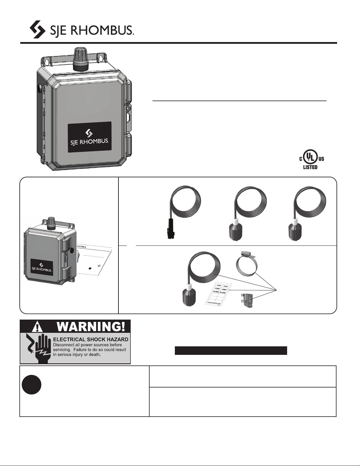
Installer Friendly Series®
Installation and Operation Manual
This control panel must be installed and serviced by a licensed electrician in
accordance with the National Electric Code NFPA-70, state and local electrical codes.
UL Type 4X enclosures are for indoor or outdoor use.
Warranty void if panel is modifi ed.
E1
For information regarding operation,
available options, or servicing
questions, please call SJE Rhombus
Technical Support.
SJE Rhombus oers a ve-year limited warranty on the control panel
and the C-Level™ sensor.
For complete terms and conditions, please visit www.sjerhombus.com.
Products returned must be cleaned, sanitized, or decontaminated as necessary
prior to shipment to ensure that employees will not be exposed to health
hazards in handling said material. All applicable laws and regulations shall apply.
?
High Water FloatRedundant O FloatC-Level™Sensor
Parts included
Manufactured by:
SJE Rhombus
Detroit Lakes, MN, USA
*Control panel may be
ordered with or without
C-Level™ Sensor/Floats. C-Level™
Sensor
Models
Float
Switch
Models 3x
or
4x
Installer Friendly Series®
Installation and Operation Manual
This control panel must be installed
and serviced by a licensed electrician
in accordance with the National Electric
Code NFPA-70, state and local electrical
codes.
UL Type 4X enclosures are for indoor or
outdoor use.
Technical support,
service questions:
1-800-Rhombus
(1-800-746-6287)
Monday - Friday
7:00 AM to 6:00 PM CST
?
Installer Friendly Series
®
OROR

Installing the C-Level™Sensor & Float Switches
The IFS control panel operates with a C-Level™ sensor and 1 or 2
recommended oat switches or with 3 to 4 oat switches. For C-Level™
sensor operation, C-Level™ sensor operates the Pump Start, Stop and
Alarm functions and the back-up oat switches are for redundant o and
high level alarm. For oat switch operation, the oat switches operate the
Pump Start, Stop and Alarm functions.
Mounting the Control Panel
NOTE
Do not splice the C-Level™ sensor
cable.
Do not run C-Level™ sensor cable
or oat switch cables in the same
conduit as the pump cables.
E2
Ensure all supply power to the control panel
is turned OFF before installing or servicing
the C-Level™ sensor, oat switches or pumps
in the tank. Failure to do so could result in
serious or fatal shock.
Power from Breaker
O
Floats require free range of motion.
They must not touch each other or
any equipment in the pump chamber.
Timed Dose
Float Switch Installation
Make sure hose clamp
band does not interfere
with oat operation.
Tighten
the
clamp.
Hose clamp is 18-8
stainless steel.
3.5”
(9cm)
Do not install cord under
hose clamp.
Demand Dose
Duplex 3-Float
Simplex Duplex 4-Float
Simplex/Duplex
Timer Override
(optional)
Alarm
Timer Enable
Redundant O
(optional)
Alarm
Start
Stop
Lag/Alarm
Start
Stop
Lag
Alarm
Start
Stop

E3
Demand Dose Application
high water
alarm oat
(recommended)
redundant
o oat
(recommended)
lag (duplex
only)
high water
alarm
start
stop
0
Timed Dose Application
high water
alarm oat
(recommended)
redundant o
oat
(recommended)
high water
alarm
timer
enable
timer
override
redundant
o
0
Float Switch Positioning
CAUTION!
If the C-Level™sensor or oat
switches are not mounted and
connected correctly, the pumps
and alarm will not operate
properly.
3.5”
(9 cm)
C-Level™ Sensor Positioning
Keep vent above water level. hose
clamp
4 inch (10.2 cm)
minimum set level
0 inch (0 cm) liquid
level measured from
approximately this point
1 inch (2.5 cm)
minimum from bottom
of tank or from sludge
hose
clamp
Stow excess tube using a
cable tie.
Caution: Do not overtighten
and pinch vent tube.
Do not use the hose clamp
to attach the vent tube.
Doing so will cause sensor
to fail.
cable
tie
C-Level™Sensor and Float Switch Installation

E4
PN 1067499A 11/21
© 2021 SJE, Inc. All Rights Reserved.
SJE Rhombus is a trademark of SJE, Inc.
Wiring the Control Panel
1Locate conduit entrance at the bottom of the enclosure as
shown. Check local codes for the number of power circuits
required. The schematic is located on the inside cover of the
control panel.
Be sure the incoming voltage is the same as the pump motor
nameplate.
Providing separate pump and control/alarm power sources is
recommended.
Type 4X conduit must be used to maintain a Type 4X rating
of the control panel.
CAUTION!
CAUTION!
Seal the electrical conduit with an approved
sealing compound to prevent moisture or
gases from entering into the control panel.
Connect the following wires to the proper terminals:
• incoming power for each pump circuit breaker
• incoming power for control/alarm
• pump 1
• pump 2 (duplex only)
• C-Level™ sensor
• oat switches (recommended)
See schematic label on inside cover of the control panel for
details.
2
Duplex Model Shown
Setup and Operation
Rotate dial and press to select the corresponding pump’s mode indicator or panel settings icon.
3Verify correct operation of control panel after installation is
complete.
If redundant o oat is not used, a jumper must be
installed in its place.
2
Alarm System (Indicator Light and Horn)
When an alarm condition occurs, the red light and
horn will be activated.
If the TEST/SILENCE button is pressed and released,
the horn will be silenced. When the alarm condition
is cleared, the alarm system is reset.
Circuit Breakers
Each pump circuit has a thermal-magnetic circuit
breaker that provides branch circuit protection and a
means to disconnect the pump.
Float Test Switches
Push to simulate a oat closure condition for each
input.
Dry Auxiliary Contacts
Normally Open - Contacts are OPEN under normal
conditions and CLOSED when alarm condition is
present. CLOSED during power loss.
Automatically resets once alarm condition is cleared.
Aux contact rating: 120V, 5A
1
2
4
3
NOTE
1
3
4
HAND
OFF
AUTO
1
HAND
OFF
AUTO
2
PUMP 2
(duplex only)
SETTINGS
Counts and ETMs - Displays pump run time and counts of pump run and alarms
Timer Settings - Congures timers (Timed Dose mode only)
Level Settings - Congures level setpoints
Alternation (duplex only) - Congures alternation mode for duplex panels
Advanced - Congure advanced functions and view troubleshooting tools
PUMP 1
HOA
Installer Friendly Series®
Soporte técnico: +1 800-746-6287
www.sjerhombus.com
Soporte técnico, Horario: Lunes a viernes 7 A.M. a 6 P.M., hora del Centro
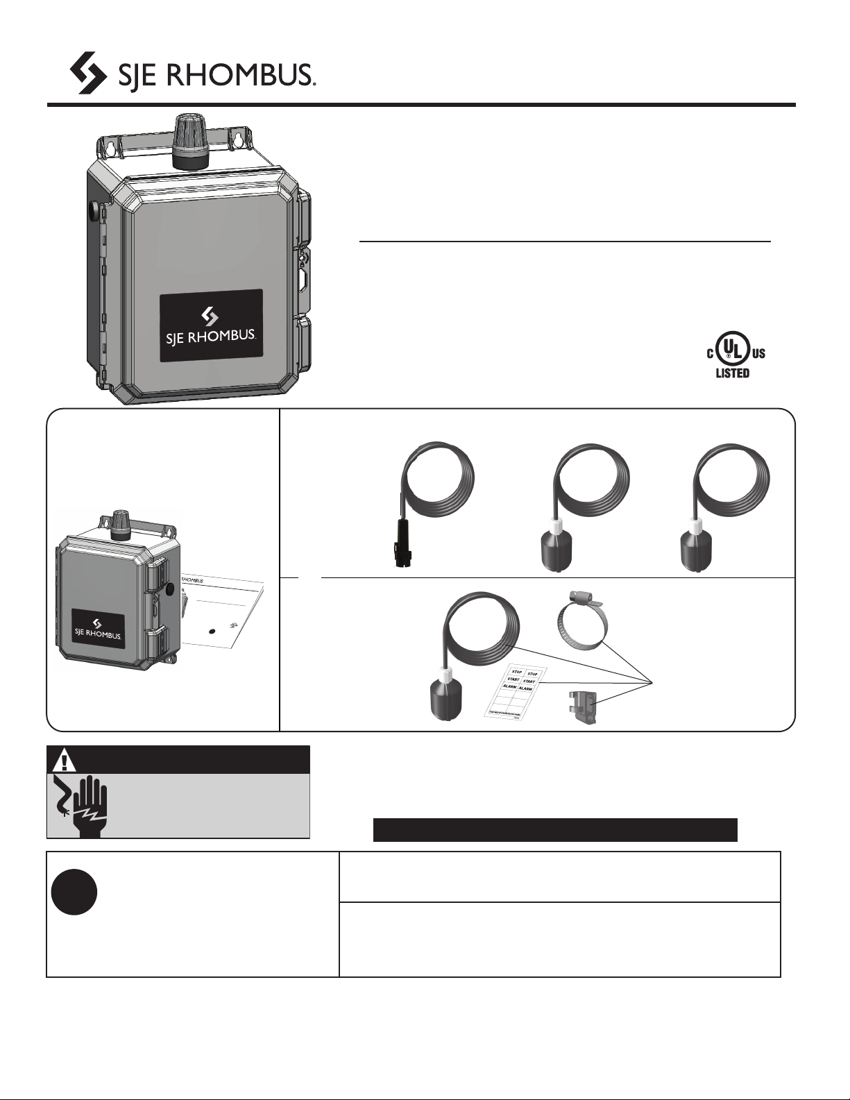
Installer Friendly Series®
Manual de instalación y operación
ADVERTENCIA
RIESGO DE CHOQUE ELÉCTRICO
Desconectar todas las fuentes de poder
antes de efectuar mantenimiento o reparaciones.
No obedecer estas indicaciones podría resultar
en serias lesiones o mortales.
La instalación, el mantenimiento y la reparación de este panel de control deben ser
efectuados por un electricista certicado conforme al Código Eléctrico Nacional de
EE.UU. NFPA-70 y los códigos estatales y locales. Las cajas/gabinetes clasicación
UL tipo 4X son para uso interior o exterior.
La garantía queda anulada si se modifi ca el panel.
S1
SJE Rhombus ofrece una garantía limitada de cinco años para el panel de
control y el sensor C-Level™. Para consultar los términos y condiciones, visite el
portal www.sjerhombus.com.
?
Flotador de
nivel alto
Flotador de
apagado redundante
Sensor C-Level™
Piezas incluidas
Fabricado por:
SJE Rhombus
Detroit Lakes, MN, USA
*Es posible solicitar el panel
de control con o sin sensor
C-Level™/otadores.
Sensor
C-Level™
Modelos
Interruptor
de otador
Modelos 3x o 4x
Installer Friendly Series®
Installation and Operation Manual
This control panel must be installed
and serviced by a licensed electrician
in accordance with the National Electric
Code NFPA-70, state and local electrical
codes.
UL Type 4X enclosures are for indoor or
outdoor use.
Technical support,
service questions:
1-800-Rhombus
(1-800-746-6287)
Monday - Friday
7:00 AM to 6:00 PM CST
?
Installer Friendly Series
®
O BIENO BIEN
Para información acerca del
funcionamiento, las opciones
disponibles o para preguntas
acerca del mantenimiento, por
favor comunicarse con Soporte
técnico de SJERhombus.
Los productos devueltos deben estar limpios, desinfectados y
descontaminados según sea necesario antes de enviarlos de modo que se
garantice que los empleados no van a estar expuestos a riesgos de salud
durante la manipulación de dicho material. Se aplicarán todas las leyes y
normas vigentes.
Other manuals for Installer Friendly Series
2
This manual suits for next models
1
Table of contents
Languages:


