skals AMV1 User manual
1
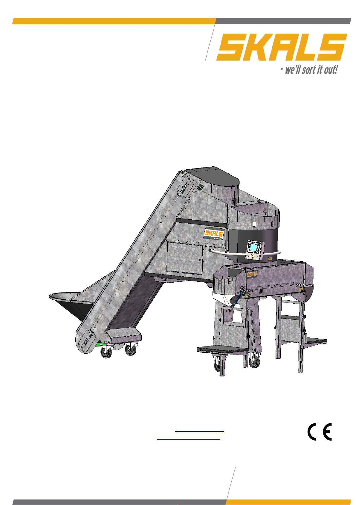
Manual
Weighing Machine
AMV1
A/S SKALS MASKINFABRIK
HOVEDGADEN 56
DK-8832 SKALS, DENMARK
Tel.: +45 87 25 62 00
Fax: +45 86 69 49 99
Email: [email protected]
http://www.skals.dk/

2
1Contents
1Contents........................................................................................................................2
2Introduction ...................................................................................................................3
3Safety ............................................................................................................................4
3.1Pictograms.......................................................................................................................... 4
4In general ......................................................................................................................5
4.1Feed belt............................................................................................................................. 6
4.2Vibration chutes.................................................................................................................. 6
4.3Weighing tank..................................................................................................................... 7
4.4Cross conveyor................................................................................................................... 8
4.5Sack platform...................................................................................................................... 9
4.6Operating panel .................................................................................................................. 9
5Operation ......................................................................................................................9
5.1Set-up ................................................................................................................................. 9
5.2Electrical connection........................................................................................................... 9
5.3Start-up............................................................................................................................. 10
6Control.........................................................................................................................11
6.1Homescreen ..................................................................................................................... 11
6.2Settings............................................................................................................................. 11
6.3Skals................................................................................................................................. 12
6.4Automatic operation settings ............................................................................................ 13
6.5Manual operation settings ................................................................................................ 17
6.6Emptying the machine ...................................................................................................... 18
7Service and maintenance............................................................................................18
7.1Bearings ........................................................................................................................... 18
7.2Gear.................................................................................................................................. 18
7.3Belt ................................................................................................................................... 18
7.4Vibration chutes................................................................................................................ 20
7.5Cleaning ........................................................................................................................... 21
8Transport.....................................................................................................................22
9Troubleshooting ..........................................................................................................23
9.1Fault described in display. ................................................................................................ 23

3
9.2Other faults. ...................................................................................................................... 24
10Spare parts list .........................................................................................................25
10.1Weighing tank................................................................................................................... 26
10.2Vibrator chute ................................................................................................................... 27
10.3Feed belt........................................................................................................................... 28
10.4Cross conveyor................................................................................................................. 29
11Diagrams..................................................................................................................31
12EU Declaration of Conformity...................................................................................32
2Introduction
Read this user manual thoroughly before using the machine.
The machine is use for weighing potatoes, onions, carrots and other similar products.
The machine can weight portion sizes from 1–50 kg.
The machine can weigh large portions up to 1000 kg.
The machine may be operated in a temperature range of -10 to +40 C°.
The information plate and CE label are positioned on the side of the machine, close to the
control panel.

4
3Safety
Any persons working in the close vicinity of the machine must not wear loose-fitting
clothing as this will be hazardous.
3.1 Pictograms
Two types of pictograms are positioned on the machine. Warnings and instructions.
Warnings
HAZARD - ROTATING PARTS.
Avoid touching or coming into contact with the machine's
moving parts. This applies to fingers and clothing, since this
can lead to mutilation.
CRUSH HAZARD.
Avoid touching or coming into contact with the machine's
moving parts. This applies to fingers and clothing, since this
can lead to mutilation.
Instructions
HOOK
Describes where the hook must be positioned when the machine is to be
lifted by a crane.
STRAP HERE
Describes where the machine shall be secured during transport.
FORKLIFT TRUCK
Describes where the forks must be positioned when lifting with a forklift
truck.

5
4In general
Description of machine
Buffer tank
Feed belt
Vibration chutes
Wei
g
hin
g
tank
Cross conveyor
Operating panel
Feed hopper
6
4.1 Feed belt
The feed belt transports the products from the feed hopper up to the buffer tank above the
vibration chutes. The buffer tank has two sensors that activate and deactivate the feed
belt.
To achieve optimal operation, it is important that the feed hopper is always filled
with products.
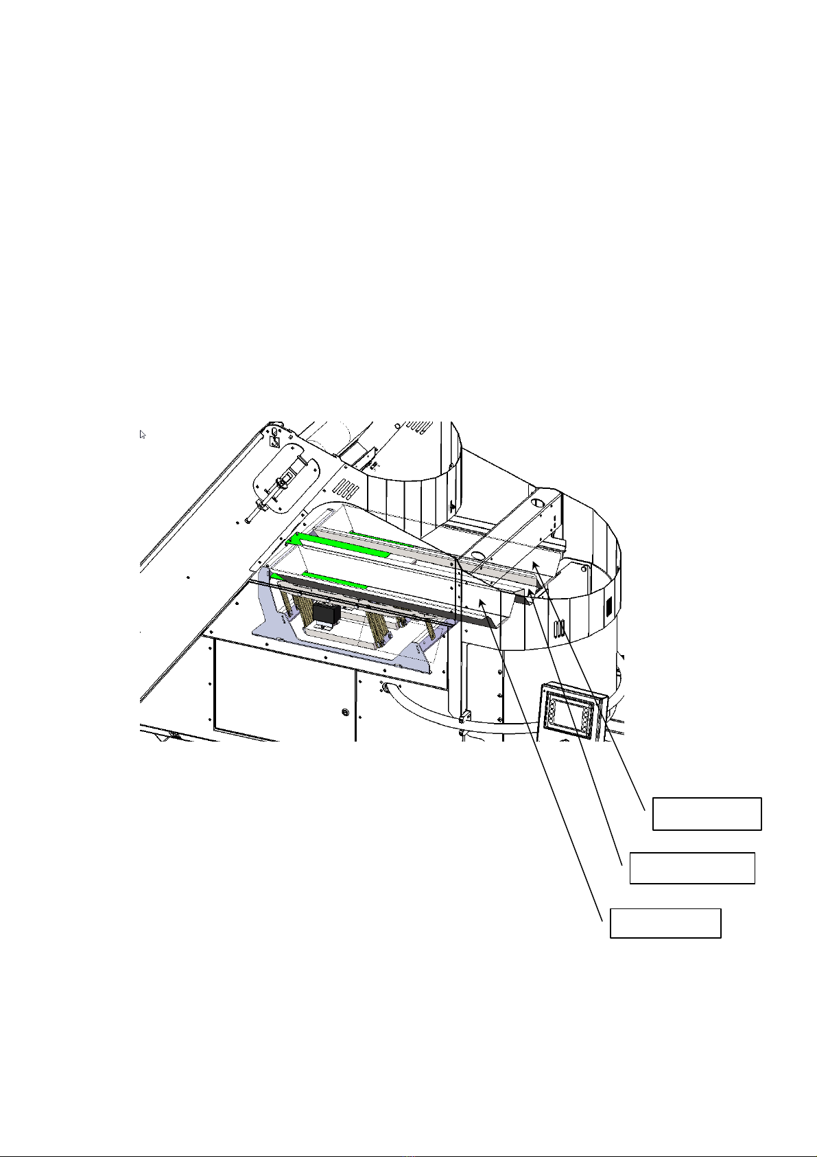
4.2 Vibration chutes
The machine is equipped with three vibration chutes, designed to fill and dose the
weighing tank.
All three of the vibration chutes switch on automatically when the weighing tank shall be
filled and only two of the chutes operate when dosing for the required weight.
Fill chute.
Dosing chute
Fill chute.

7
4.3 Weighing tank
The weighing tanks' volume capacity is 57 l.
The weighing tank must be checked regularly and if required, cleaned of any soil that has
accumulated.
During operation, the weighing tank must not be touched otherwise the weighing result will
not be correct.

8
4.4 Cross conveyor
The cross conveyor allows the machine to be operated by two people at the same time.
When the operating sensor is activated on a specific side, the cross conveyor will transport
the next portion to that side.
NB: The machine 'remembers' an activation of the operating sensor, even though the
cross conveyor is not ready to deliver a portion!
The machine is supplied with four outlet hoppers as standard. Two hoppers for portion
sizes 1–9 kg and two hoppers for 10–50 kg.
Outlet hopper
Operation sensor
Sack platform
Handle for stabiliser leg
Outlet hopper 10–50 kg Outlet hopper 1–9 kg
9
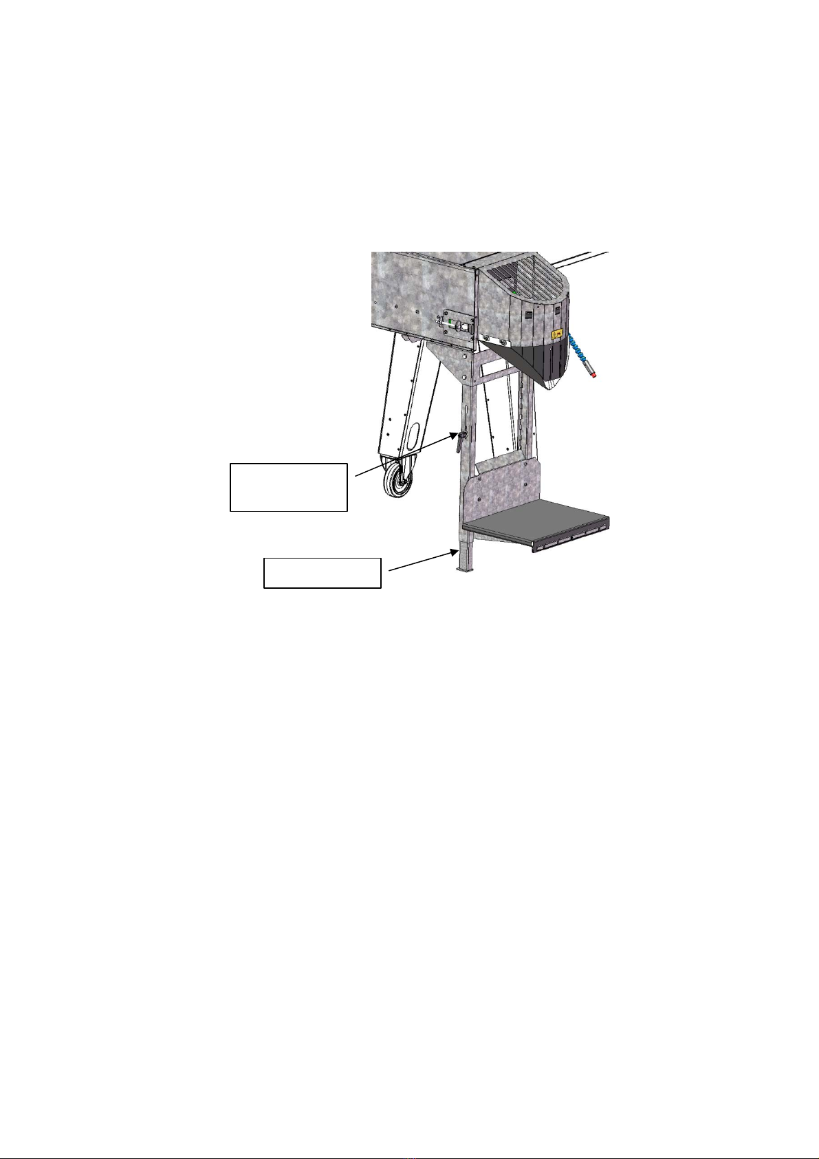
4.5 Sack platform
When the height of the sack platform shall be changed, loosen the two finger screws on
the platform and raised/lower the platform and then re-tighten the finger screws.
When weighing portions that weigh more than 10 kg, lower the stabiliser leg at the sack
platform until it supports on the level surface.
4.6 Operating panel
The operating panel consists of a touch display and a stop.
All of the machine's electrical functions are operated via the touch display.
5Operation
Before commissioning the machine, check it to ensure it has not been damaged during
transport.
Any defects must be reported to the dealer immediately.
5.1 Set-up
To ensure correct weighing, the machine must be placed on a stable and level surface.
5.2 Electrical connection
The electrical connection must comply with national applicable regulations.
1 Phase 230 V - N + PE
Stabiliser leg
Handle for
stabiliser le
g

10
5.3 Start-up
1. Enter the desired portion size and total number of portions that are to be weighed
using the operating panel.
2. Next, select the programme that is to be used (potatoes, carrots, onions or
optional).
3. Press the "Start" button on the display.
4. The operating sensor is activated.
NB: In the case of start-up after the portion size has been changed the machine may
initially weigh inaccurately. The machine will regulate this automatically after a few
weighings.
11
6Control
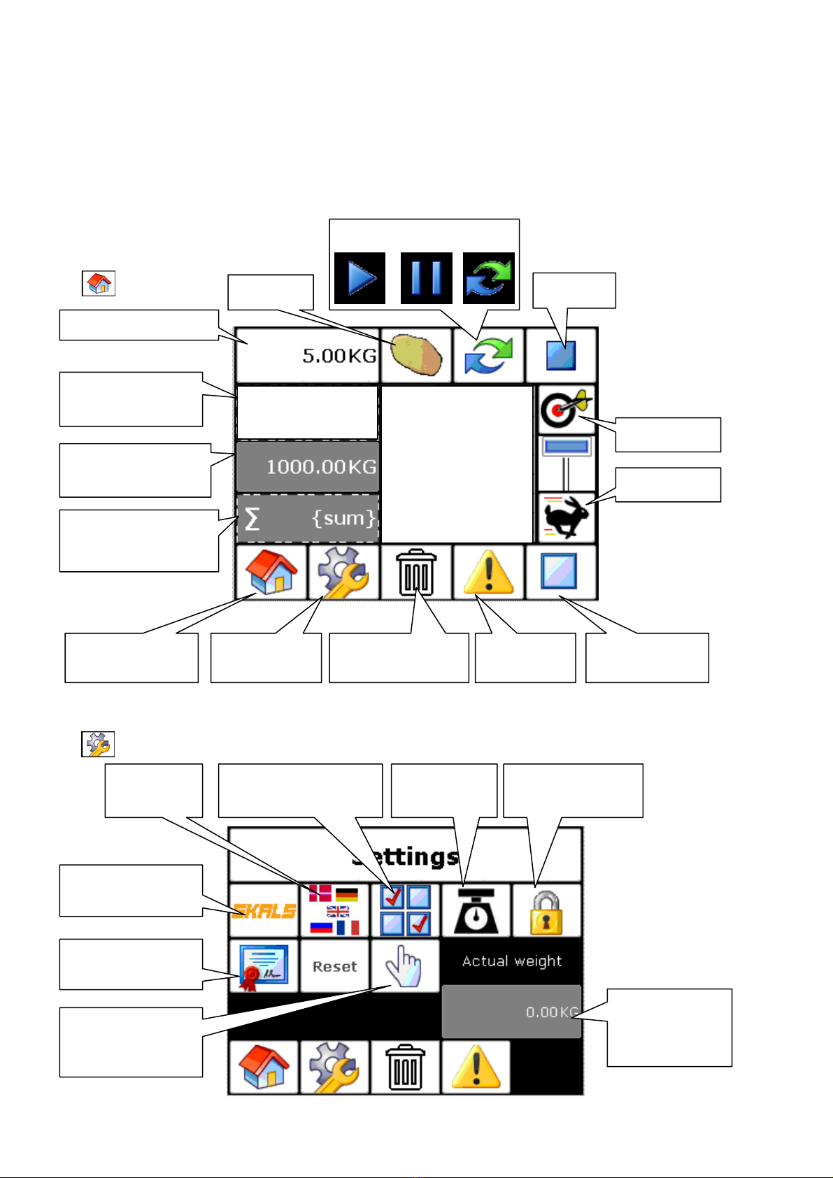
6.1 Homescreen
6.2 Settings
Portion sizes
Total number of
portions
Actual weight in
the weighing tank
∑Sum of weighings
X Average value
ϬStandard deviation
Return to
homescreen
Settings Empty function Alarms
Precision
Product
Start/Pause/Repeat
Stop
Reset alarms
Speed
6/10 6 5.01 kg
5 5.10 kg
4 5.04 kg
3 5.00 kg
2 5.03 kg
1 5.07 kg
Skals contact
information
Verification
Actual weight
in the
weighing tank
Language
setting
Automatic
operation settings
Scales settings
locked
Calibration
of scales
Manual
operation
settings

12
6.3 Skals
Skals contact information is shown here
Should you have any questions about the machine, contact your dealer in the first
instance.
Verification
The verification ID and date of last filling is show here.
13
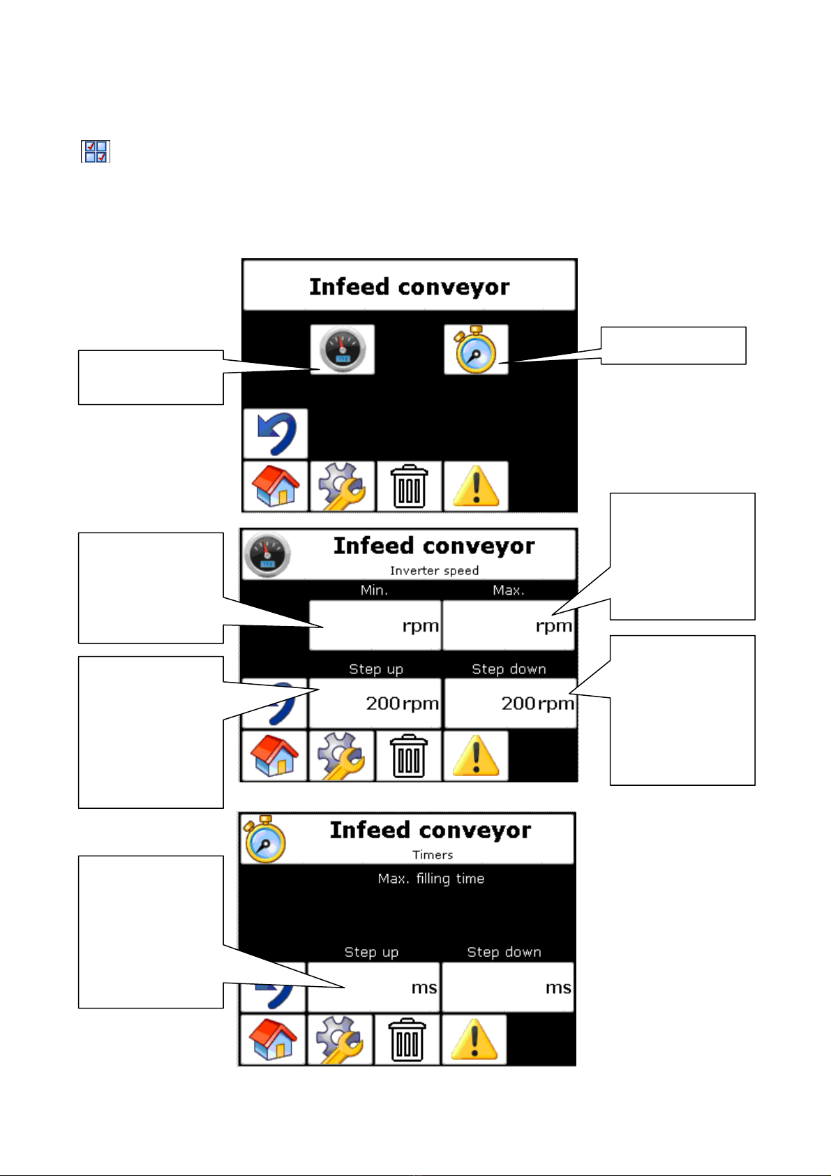
6.4 Automatic operation settings
There are four areas that can be set: Feed belt, vibration chutes, weight and cross
conveyor, of which the last three are relevant for normal operation.
Feed belt
Minimum rpm of
the drum motor
for the feed belt
should be set to
700 rpm.
Total rpm, the
drum motor
speed lowers
every time it de-
accelerates.
Should not be
changed.
Total rpm, the
drum motor
speed increases
every time it
accelerates.
Should not be
changed.
Maximum rpm
of the drum
motor for the
feed belt should
be set to
1500 rpm.
Time interval
between
automatic
change of
speed.
Speed, see next
image
Time setting
700 1500
1000 2000
14
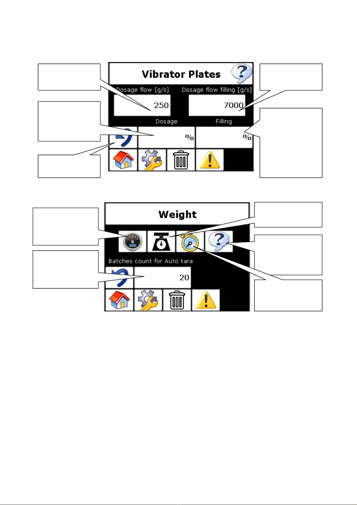
Vibration chutes
Scales
Auto taring
Automatically tares the scales zero point after a set number of portions (e.g. 20).
In the case of dirty products, it is relevant to have a low total number of weighings between
each auto taring. Build up of dirt in the weighing tank affects the weighing result.
Motor speed for
tank shutter
Should not be
chan
g
ed.
Total number of
portions between
each auto taring.
See explanation
Scales settings
See next image
Back to
previous menu
Estimated flow
when dosing
Vibration power
in percent.
Should not be
less than 55%
and should
always be
greater than
c
h
ute
2
Vibration power
in percent.
Should not be
less than 50% 75 85
Estimated flow
when filling
Product specific
settings.
(potatoes, carrots
etc.)
Alarm times
Should not be
changed.
15
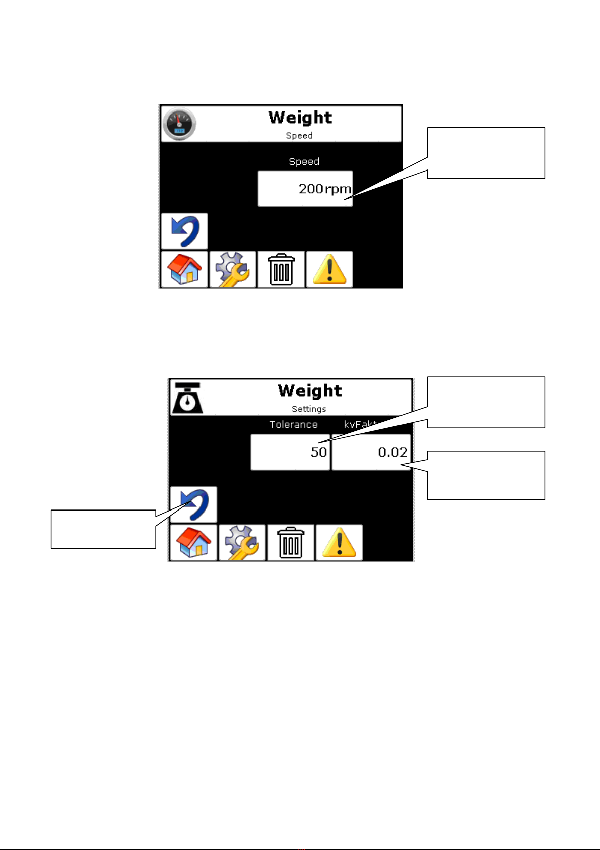
Weight Speed
Weight settings
Offset 25 kg:
When a double portion is made (over 25 kg), Offset 25 kg must be between 1500 and
3500 g to stop around the 25 kg. This is necessary to compensate for the run-on time and
prevent the weighing tank from becoming over filled with the first portion.
Tolerance
This is the limit for when the scales begins to be regulated.
If the products that are being weighed weigh up to 100 g, the tolerance must be the same
or 10 % greater.
Controller parameter
Parameter that determines how aggressive the controller reacts
Back to
previous menu
Controller
parameter
Tolerance interval
in grams, see
explanation
Weigher opening
speed
16
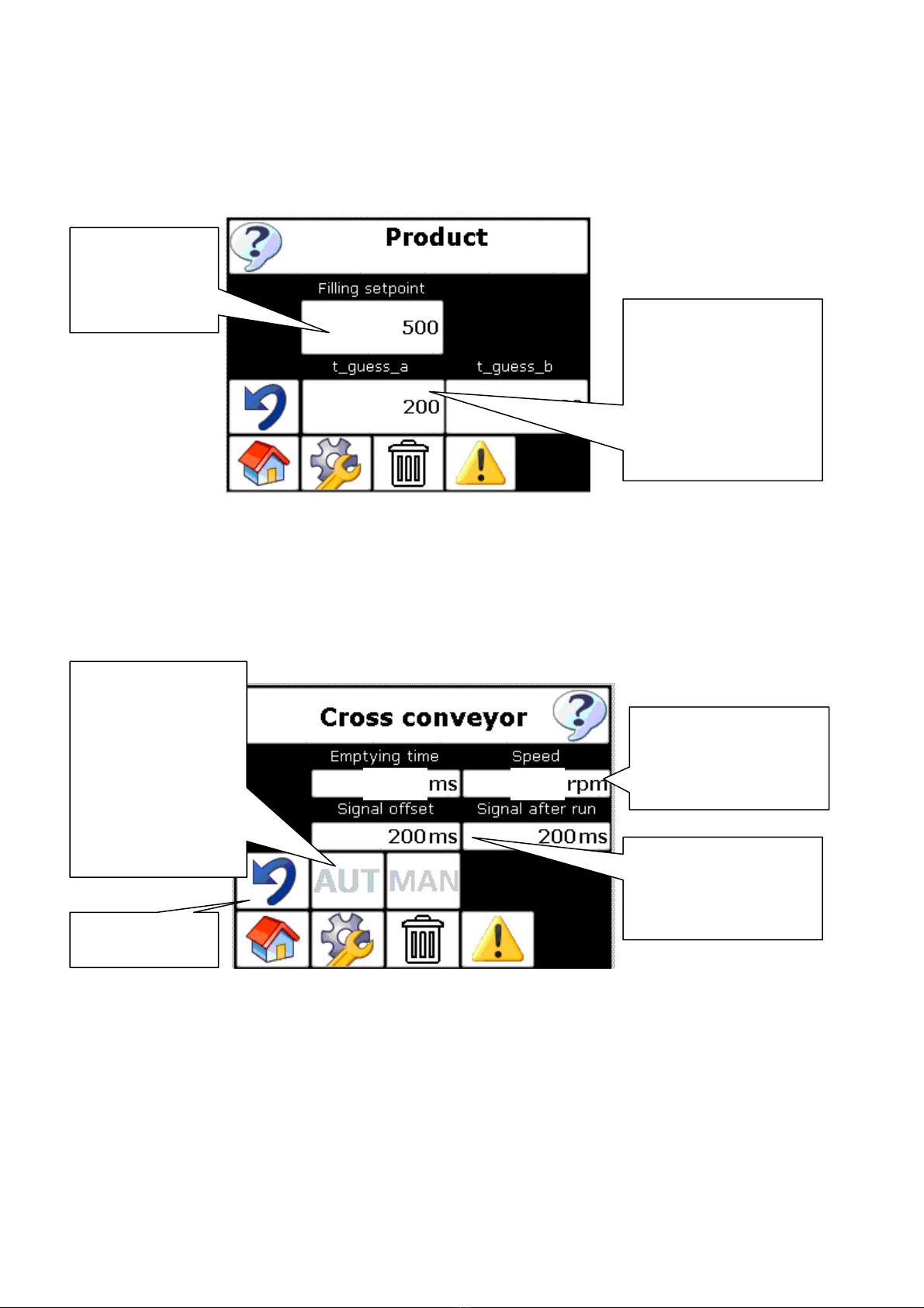
Product specific parameters
Cross conveyor
Empty time
The time that is set to ensure that the belt is completely empty.
Speed
If there are problems with the products coming out of the outlet hopper, reduce the speed.
Filling setpoint
is controlled by
the slider on
the main page
Delay and run-signal
to next machine
External signal
Back to
previous menu
2300 700
Time guess_a is a
value used for
portions up to 10kg.
Lighter products =
higher value.
The speed of the
cross conveyor
should be between
600 and 900 rpm
Aut. or manual
outfeed mode.
Manual = sensor
Aut. = after first
touch of the
sensor, next
portions are
feeded
automatically

17
6.5 Manual operation settings
During manual operation, all of the functions can be set and the machine operated.
NB: In manual operation mode, all of the alarms and sensors are de-activated.
Language
Five languages are available.
English
German
Danish
French
Russian
Lock
When the scales are locked, there is limited access to certain functions.
Scales guide
Programme 0-3
Scales guide (calibration)
To calibrate the scales, follow the instructions in the display.
Place a known weight in the weighing tank during calibration.
The weighing tank must be clean inside.
Every time the scales are calibrated a new ID number is generated, which can be seen
under the verification ID and a date for the last calibration.
Alarms
All of the alarms that can be triggered are shown in the troubleshooting section.
When an error is observed and corrected, the alarm is reset

18
6.6 Emptying the machine
If the machine is to be completely emptied, continue to weigh portions without filling the
intake hopper with any products. Once the vibration chutes have operated for a longer
period than normal, press Stop.
Next, empty the weighing tank and the cross conveyor by accessing the manual settings
and press to empty.
7Service and maintenance
During service and maintenance, ensure power has been disconnected at the main switch
and the main switch is locked.
7.1 Bearings
All of the bearings and motors and the loose drum have been lubricated at the factory and
require no maintenance.
7.2 Gear
The worm gear that drives the weighing tank's open/close function has been lifetime
lubricated with synthetic grease for operation in standard temperature range (-10 to +40
°C).
7.3 Belt
The machine has two PVC belts fitted. A feed belt and a cross conveyor.
Both belts must be checked regularly and adjusted if required to ensure a long lifetime.
Tighten the belts by loosening the two nuts marked with blue (on both sides) and then
tighten the belt by tightening the top nut. Once the belt has been adjusted, re-tighten the

19
bottom nut. The same procedure is used to adjust the belt to operate in the centre.
However, the tightening must only be done in the side the belt moves to.
At all times it is the responsibility of the owner to ensure the belts have been adjusted
correctly.
If the belts have not been adjusted correctly, the warranty for the belts is void.
20
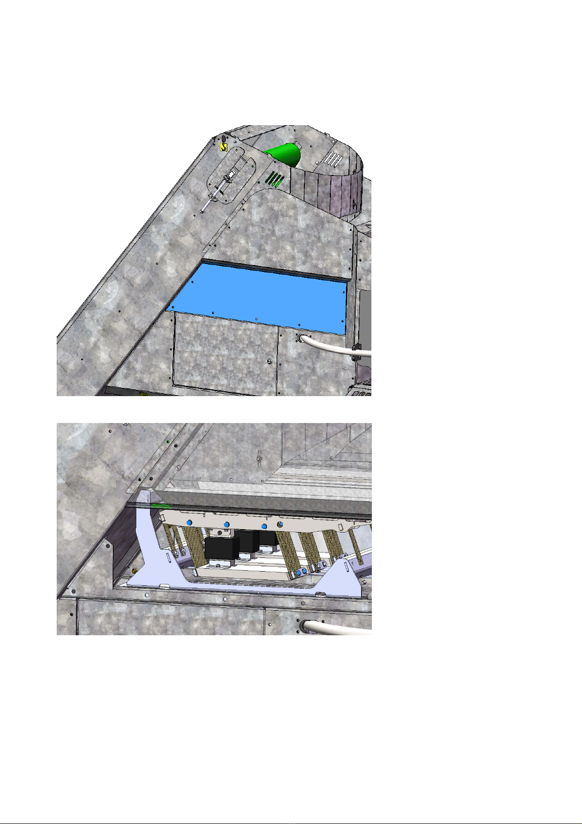
7.4 Vibration chutes
All bolts and vibration chutes should be re-tightened every 200 hours of operation.
To access the bolts, remove the screen marked in blue.
The bolts are marked in blue, and should be tighten to 18 Nm.
Table of contents


