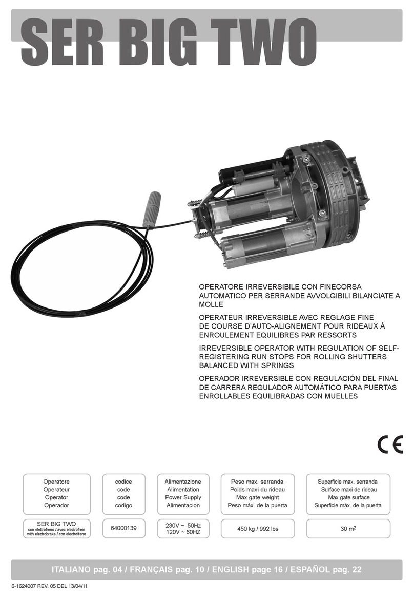
Skeleton Technologies SkelStart Assembly instructions

INSTALLATION GUIDE
AND USER MANUAL
www.skeletontech.com
02-SMC-210408-1B
Skeleton Technologies
SkelStartTM Engine Module
12V / CCA 2100
Keep this user manual in your vehicle.

32
About the SkelStartTM
Engine Module
The SkelStart enables drivers to start a vehicle
engine in situations where the engine cannot be
started by normal batteries owing to, for example,
extreme weather conditions or aged batteries, or
start the engine. The SkelStartTM is able to supply
What do you need
for installation?
The additional materials that may be needed for
installation are listed below. These items are not
included with the SkelStartTM, but may be
necessary for isolating other vehicle electronic
non-starting loads from the starter system.
+bolt, washer, nut (M8)
+electrical insulation material (heat shrink)
for proper insulation
+cable to connect other vehicle electronic
non-starting loads to the positive (+)
battery terminal
+standard shop tools
WARNING
SKELSTART IS NOT A BATTERY
HIGH CURRENT HAZARD
DO NOT CONNECT CABLES FROM
THE BATTERY TO THE STARTER (S+)
TERMINAL OF THE SKELSTART
DO NOT CONNECT IN REVERSE POLARITY
DO NOT JUMP-START
DO NOT DROP THE SKELSTART
DO NOT SHORT CIRCUIT
Installing the
SkelStartTM
Mounting location
SkelStartTM installation usually requires the
installation of a bracket or a shelf on which to place
the Module. The shelf must be in a safe location,
away from any direct heat sources.
The Starter
Positive (+) Terminal
Status Button
Status Indicator (LED) Fig 1. SkelStartTM 12V
Electrical installation
Do not connect cables from the battery
to the starter (S+) terminal of the SkelStart.
Cable selection
To install the SkelStartTM, you need new cables
from the “S+” terminal to the Starter Solenoid “+”
(positive) terminal and from the “B−” and “B+”
terminals to the vehicle mass, and 24V.
Pre-installation checks
Before installation of the SkelStartTM, you need to
remove all the cables from the vehicle batteries.
The vehicle batteries need to be charged. Clean the
battery terminals to remove any oxidation or grease.
Length of cable (m) 4.5–6 6.1–7.5 7.5–9 9.1–12
Cable size (mm2) 35 50 50 70
SkelStartTM
The battery
Positive (+) Terminal
yrettabehT
Negative (-) Terminal
(ground connection)
Unit SkelStartTM 12V
Weight kg 8.5
Dimensions mm 328(l) x 171(w) x 241(h)
Charging current A 16 (max)
Charging voltage range V 9–16
Operating temperature °C −40 to +65
Cold Cranking Amps (CCA)* A 2133
Maximum engine size L 16
Charge time (from 0 V) min 19
Standby current draw mA <10
Output voltage V 14.1 (max)
Peak power** kW 62.9
* Based on 1s ESR
** Based on 10ms ESR

12V SkelStartTM
12V
Starter
12V
Alternator
Wiring instructions
1. Before installation, remove all the cables from the
vehicle batteries.
NOTE: Do not connect the SkelStartTM
before instructed to do so!
2. Most vehicle manufacturers connect the alternator
and other vehicle power cables to the starter
solenoid’s positive terminal. Therefore, all the cables
connected to the Starter Solenoid’s positive terminal
need to be removed (Fig. 2 cables 1, 2, 3 - cable 3 can
consist several cables). Note: the starter can include
an integrated magnetic switch, in which case the
short cable from the magnetic switch to the starter
can remain connected to the positive starter terminal.
3. The cables removed from the positive starter
solenoid terminal should be connected using a
terminal block or a nut–bolt connection (use spring
washer or locknut). This connection will then have
to be isolated from the rest of the vehicle and
mounted securely. This can be achieved by bundling
the cables together using cable ties and covering the
connection with heat shrink (Fig 3. cables 1,2,3).
Note: the connection must be fully isolated from
the mass of the truck and should be secured in such
a way that vibration, abrasion or corrosion cannot
cause a short circuit.
4. Construct a new cable to connect the SkelStartTM
S+ to the positive terminal of the Starter Solenoid
(Fig. 3 cable 4). The recommended cable size - based
on the length of the total cable - can be found in the
above table.
5. Construct an additional new cable to connect the
SkelStartTM B+ to the 12 V line on the batteries
(Fig. 3 cable 6). The cable size should be at least
25 mm2 for lenghts of <5 m and 35 mm2when the
cable length exceeds 5 m.
6. Finally, a new cable is required for connecting the
SkelStartTM B- terminal with battery "-" terminal or to
the vehicle mass (Fig. 3 cable 5). This cable should be
sized according to the above table.
7. After assembling the cables, mount the SkelStartTM
securely and connect B+ terminal with the battery
"+" terminal. Then connect SkelStart B- terminal
with battery “-” terminal. In addition, reconnect the
vehicle batteries. Do not connect the starter cable yet.
8. Before making the nal connection, measure
the voltage between the starter cable and both the
positive and negative connections on the SkelStartTM.
In both cases, the multimeter should read 0 V.
A voltage reading other than zero between the starter
cable and either the positive or negative connections
on the SkelStartTM indicates that the starter solenoid
may be unreliable or that there is another path from
the solenoid to the batteries. Connecting the
SkelStartTM in this state can be dangerous and must
be corrected before continuing with the installation.
9. If the voltage reading between the starter cable
and both of the battery terminals reads 0V, then the
cable leading from the starter can be connected to the
SkelStartTM.
10. After ensuring that all the connections have been
fastened securely, the device is ready to be switched
ON. This is achieved by holding the power button for
5 seconds.
11. Charging has been successfully initiated when
the inbuilt green LED starts to ash slowly. This will
continue to ash until the SkelStartTM is fully charged.
12. When the charging stops, the SkelStartTM is ready
to be used to start your engine!
Fig 2. 12V system before SkelStartTM installation
Fig 3. 12V system after SkelStartTM installation
*12V SkelStartTM can be used to replace existing battery.
In 12V parallel connection minimum of one battery is required.
54
1
2
3
4
5
6
12V
Starter
12V
Alternator
1
2
3

SkelStart discharge
Prior to storing or packing the SkelStartTM, please
discharge as follows:
1. If the voltage between the SkelStartTM “S+”
terminal and the “−“ terminal of the batteries is
above 2V
a) Switch OFF the SkelStartTM by holding down the
button for 5 seconds.
b) Disconnect all the cables from the SkelStartTM.
c) Connect a 12V load, such as a headlight (or two
12V headlights connected in series) or a 12V blower
motor, across the “S+” and “B−” terminals. Leave
them connected until the light goes out or until the
blower motor stops running. This will discharge
the voltage stored in the SkelStartTM.
d) Verify that the voltage is 2V or less.
e) DO NOT use a cable, bare wire or low-/no-
resistance conductor to discharge the SkelStartTM!
2. Using a voltmeter, measure the voltage between
the “S+” and “B−” terminals. If the voltage is less
than 2V, the SkelStartTM is now considered safe for
handling and shipping.
Switching the SkelStart ON/OFF
The SkelStart includes a green light-emitting diode
that displays the status of the unit when the button
is pressed. Holding the button for 5 seconds will turn
the device ON or OFF.
NOTE: This will only affect the charging circuit;
it will not discharge the device or make it safe to
handle if fully charged.
A short press of the button will indicate the state
ofthe device; a single short ash will indicate that the
device is ON. In the OFF state, there is no response.
A blinking LED shows that the SkelStart is charging.
NOTE: if there is dust on the button, it should be
removed prior pressing the button.
Taking care of your SkelStartTM
The terminals should be periodically checked for
oxidation or for loose connections and should be
cleaned or tightened as necessary. Prior to removal or
system maintenance, ensure that the module has
been discharged. No other maintenance is necessary.
+incinerate +recycle with batteries
+crush +dispose of in trash
Dispose in accordance with the local regulations
for electronic waste.
Jump Starting
If a jump start is required, do not connect the jump
start cables directly to the SkelStart. Connect the
jump start cable to the batteries or to a junction box.
Guidelines for handling after
extended period of parking
If the vehicle does not crank the following procedure
should be followed:
+Make sure that the batteries are in charged to
specied limit
+Make sure that SkelStart is turned on and ready to
use. This can be done by pressing the button. After
which the LED will be lit for 5 sec.
+If led does not light up this means that the device is
not ON. To turn on the device press the button for 5
sec. If there is a need for the device to charge the led
will remain blinking.
+If the led stops blinking this means that the device
is ready to use. This can be validated by pressing the
button and led will be lit for 5 sec.
Removing the SkelStart from
the system temporarily
If there is a need to restore current ow directly from
the batteries to the starter, remove the cable from
SkelStart B+ terminal (battery + to SkelStart cable).
Then remove the cable from SkelStart S+ terminal
(starter to SkelStart cable). After removing cables
from terminals connect these two cables together
with a strong electrical connection. This restores
current ow from batteries to starter, leaving the
SkelStart out of the system.
NOTE: before this procedure disconnect cables
from batteries and make sure you don't touch
S+ terminal with a metal/conductive element
connected with ground.
6 7
WARNING
HIGH CURRENT HAZARD!
Power terminals pose an arcing hazard when the SkelStart is being charged.
Make sure to always discharge the SkelStart before removing
it from the system or handling it.
DO NOT CONNECT IN REVERSE POLARITY!
Do not connect the terminals in reverse (+ to - and/or - to +).Arcing will occur
if the SkelStart is charged, creating a electric shock and/or burn hazard.
The SkelStart will be permanently damaged.
WARNING
DO NOT CONNECT THE CABLES FROM THE BATTERY TO THE STARTER+
TERMINAL OF THE ESM. IT WILL CAUSE THE BATTERY
TO SHORT CIRCUITAND CAUSE ARCING.
WARNING
WARNING - THIS IS N
12V SkelStart recommended input voltage range 9-16V.
Do not operate/charge above 30V continuous/32V momentary
OT A BATTERY - DO NOT JUMP START ON THE ESM!
Do not connect battery or jump start cable across the STARTER + “S+” and
BATTERY - “B-” terminals. Chance of damage to the battery.
WARNING
Do not operate the SkelStart above the specified temperature range (+65°C / +149°F)
Make sure to protect the terminals from accidental shorting.
If a jump start is required, use an external jump post if possible, or jump across
any battery positive (+) and battery negative (-) terminal.
Avoid installing in locations with potentially high
temperatures. Higher temperatures have a negative
impact on lifetime.
Disposal
For your SkelStartTM, do not:

Headquarters
Skeleton Technologies GmbH
Schücostraße 8, Großröhrsdorf 01900, Germany
info@skeletontech.com
www.skeletontech.com

X-ON Electronics
Largest Supplier of Electrical and Electronic Components
Click to view similar products for Supercapacitors / Ultracapacitors category:
Click to view products by Skeleton Technologies manufacturer:
Other Similar products are found below :
C-TEC1225 P LX055105A SCCY73B407SLBLE FE0H473ZF MAL223551012E3 MAL223551014E3 MAL223551015E3
MAL223551016E3 MAL223551006E3 MAL223551007E3 MAL223551001E3 MAL223551008E3 MAL219612474E3 MAL219632473E3
DRE10/2.5 DRL106S0TI25RRDAP DRL226S0TK25RR 106DCN2R7M SCCT30B156SRB SCMR14C474MSBA0 SCMR22C155MSBA0
FT0H225ZF TV1020-3R0605-R SCCX50B207VSB PAS0815LS2R5105 HVZ0E475NF SCMR18F105PSBA0 FT0H565ZF FE0H224ZF
FCS0H473ZFTBR24 SCCT30E156SRB MAL222090006E3 SCCY68B407SSBLE CPH3225A-2K SCMT22C505PRBA0 207DCN2R7M
DB5U307W35050HA DB5U407W35060HA SCCX50B227SSBLE DGH505Q5R5 DGH505Q2R7 DGH705Q2R7 DGH506Q2R7
DGH357Q2R7 DGH335Q2R7 DGH256Q2R7 DGH255Q5R5 DGH207Q2R7 DGH155Q5R5 DGH107Q2R7
Table of contents

