manuals.online logo
Brands
  1. Home
  2. •
  3. Brands
  4. •
  5. MTU
  6. •
  7. Engine
  8. •
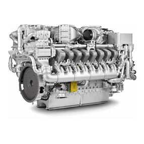
  9. MTU 12 V 4000 G21R User manual

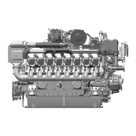
MTU 12 V 4000 G21R User manual

Other manuals for 12 V 4000 G21R

1

This manual suits for next models

1

Other MTU Engine manuals

MTU 20V4000L33F User manual

MTU

MTU 20V4000L33F User manual

MTU 12 V 2000 M84 User manual

MTU

MTU 12 V 2000 M84 User manual

MTU 16V4000M*3 series User manual

MTU

MTU 16V4000M*3 series User manual

MTU 20 V 4000 C22 User manual

MTU

MTU 20 V 4000 C22 User manual

MTU 12V2000M84 User manual

MTU

MTU 12V2000M84 User manual

MTU 12 V 2000 M84 User manual

MTU

MTU 12 V 2000 M84 User manual

MTU 8 V 2000 M9x User manual

MTU

MTU 8 V 2000 M9x User manual

MTU 20V4000G*3 series User manual

MTU

MTU 20V4000G*3 series User manual

MTU 12V4000G34F User manual

MTU

MTU 12V4000G34F User manual

MTU 12 V 4000 M33F User manual

MTU

MTU 12 V 4000 M33F User manual

MTU 20V4000G44F User manual

MTU

MTU 20V4000G44F User manual

MTU 12 V 4000 G23 Guide

MTU

MTU 12 V 4000 G23 Guide

MTU 12V2000Gx6 series User manual

MTU

MTU 12V2000Gx6 series User manual

MTU 12V4000M93 series User manual

MTU

MTU 12V4000M93 series User manual

MTU 12V 4000 L64 User manual

MTU

MTU 12V 4000 L64 User manual

MTU 10V1600C Series User manual

MTU

MTU 10V1600C Series User manual

MTU 20V4000L32FB User manual

MTU

MTU 20V4000L32FB User manual

MTU C13 User manual

MTU

MTU C13 User manual

MTU 8V2000M40A User manual

MTU

MTU 8V2000M40A User manual

MTU 12 V 4000 M63 User manual

MTU

MTU 12 V 4000 M63 User manual

MTU 20V 4000 L62 User manual

MTU

MTU 20V 4000 L62 User manual

MTU MW15406/17E User manual

MTU

MTU MW15406/17E User manual

MTU 12 V 4000 M93 x User manual

MTU

MTU 12 V 4000 M93 x User manual

MTU 12V4000M73 series User manual

MTU

MTU 12V4000M73 series User manual

Popular Engine manuals by other brands

Nakanishi EM-3030T Operation manual

Nakanishi

Nakanishi EM-3030T Operation manual

Siemens COMBIMASTER CM12 operating instructions

Siemens

Siemens COMBIMASTER CM12 operating instructions

Bosch Rexroth Hagglunds CA Series Installation and maintenance manual

Bosch

Bosch Rexroth Hagglunds CA Series Installation and maintenance manual

Hyundai H170VC manual

Hyundai

Hyundai H170VC manual

Graco 273199 repair parts

Graco

Graco 273199 repair parts

MOTO GUZZI BREVA V1100 Workshop manual

MOTO GUZZI

MOTO GUZZI BREVA V1100 Workshop manual

Dualsky Track & Field Z5 instruction manual

Dualsky

Dualsky Track & Field Z5 instruction manual

Rotax 125 senior MAX evo installation manual

Rotax

Rotax 125 senior MAX evo installation manual

Kohler K361 Service manual

Kohler

Kohler K361 Service manual

MTD OHV Series user guide

MTD

MTD OHV Series user guide

Mercury D4.2L D-Tronic manual

Mercury

Mercury D4.2L D-Tronic manual

Perkins 1206E-E66TA Operation and maintenance manual

Perkins

Perkins 1206E-E66TA Operation and maintenance manual

Skov DA 174 Technical user guide

Skov

Skov DA 174 Technical user guide

Rotax 915 i A SERIES Maintenance manual

Rotax

Rotax 915 i A SERIES Maintenance manual

AL-KO PRO 350 Instructions for use

AL-KO

AL-KO PRO 350 Instructions for use

Nanni N3.30 Workshop manual

Nanni

Nanni N3.30 Workshop manual

Nanni N5.160 CR2 Operator's manual

Nanni

Nanni N5.160 CR2 Operator's manual

Robin EC13V Instructions for use

Robin

Robin EC13V Instructions for use

manuals.online logo
manuals.online logoBrands
  • About & Mission
  • Contact us
  • Privacy Policy
  • Terms and Conditions

Copyright 2025 Manuals.Online. All Rights Reserved.

Operating Instructions
Diesel engine
12 V 4000 G21R
12 V 4000 G41R
MS150064/01E
Printed in Germany
© 2011 Copyright MTU Friedrichshafen GmbH
This Publication is protected by copyright and may not be used in any way whether in whole or in part without the prior
written permission of MTU Friedrichshafen GmbH. This restriction also applies to copyright, distribution, translation, micro‐
filming and storage or processing on electronic systems including data bases and online services.
This handbook is provided for use by maintenance and operating personnel in order to avoid malfunctions or damage
during operation.
Subject to alterations and amendments.
Commissioning Note
Important
Please complete and return the “Commissioning Note” card below to MTU Friedrichshafen GmbH.
The Commissioning Note information serves as a basis for the contractually agreed logistic support (war‐
ranty, spare parts, etc.).
Table of Contents
1 Safety
1.1 General conditions 7
1.2 Personnel and organizational requirements 8
1.3 Transport 9
1.4 Crankshaft transport locking device 10
1.5 Safety regulations for startup and operation 13
1.6 Explosion hazard when removing
inspection port cover on engine 14
1.7 Safety regulations for maintenance and
repair work 15
1.8 Fluids and lubricants, fire prevention and
environmental protection 18
1.9 Conventions for safety instructions in the
text 20
2 General Information
2.1 Engine side and cylinder designations 21
2.2 Engine layout 22
3 Technical Data
3.1 12V 4000 engine data, continuous
operation, variable 3B, optimized fuel
consumption 23
3.2 12V 4000 engine data, continuous
operation, variable 3B, emissions optimized
w/o certificate 27
3.3 12V 4000 engine data, continuous
operation, variable 3B, emissions optimized
(TA-Luft) 31
3.4 Final compression pressure 34
3.5 Firing order 35
3.6 Engine – Main dimensions 36
4 Operation
4.1 Putting the engine into operation after
extended out-of-service periods (>3
months) 37
4.2 Putting the engine into operation after
scheduled out-of-service-period 38
4.3 Start engine in manual mode (testing
mode) 39
4.4 Starting the engine in emergency situations
(override mode) 40
4.5 Operational checks 41
4.6 Stop engine in manual mode (testing
mode) 42
4.7 Emergency stop 43
4.8 After stopping the engine – Engine remains
ready for operation 44
4.9 After stopping the engine – putting the
engine out of service 45
4.10 Plant – Cleaning 46
5 Maintenance
5.1 Maintenance task reference table [QL1] 47
6 Troubleshooting
6.1 Troubleshooting 48
6.2 Fault messages on engine governor 51
7 Task Description
7.1 Engine 63
7.1.1 Engine – Barring manually 63
7.1.2 Engine – Barring with starting system 64
7.1.3 Engine – Test run 65
7.2 Cylinder Liner 66
7.2.1 Cylinder liner – Endoscopic examination 66
7.2.2 Cylinder liner - Instructions and comments on
endoscopic and visual examination 68
7.3 Crankcase Breather 70
7.3.1 Crankcase breather – Oil separator
replacement, diaphragm check and
replacement 70
7.4 Valve Drive 72
7.4.1 Valve gear – Lubrication 72
7.4.2 Valve clearance – Check and adjustment 73
7.4.3 Cylinder head cover – Removal and
installation 75
7.5 Injection Pump / HP Pump 76
7.5.1 HP pump – Relief bore check 76
7.6 Injection Valve / Injector 77
7.6.1 Injector – Replacement 77
7.6.2 Injector – Removal and installation 78
7.7 Fuel System 83
7.7.1 Fuel system – Venting 83
MS150064/01E 2011-11 | Table of Contents | 5
DCL-ID: 0000014840 - 001
7.8 Fuel Filter 84
7.8.1 Fuel filter – Replacement 84
7.8.2 Fuel prefilter cleaning 85
7.8.3 Fuel prefilter – Differential pressure gauge
check and adjustment 86
7.8.4 Fuel prefilter – Draining 87
7.8.5 Fuel prefilter ‒ Flushing 88
7.8.6 Fuel prefilter – Filter element replacement 90
7.9 Charge-Air Cooling 92
7.9.1 Intercooler – Check drain for coolant leakage
and obstruction 92
7.10 Air Filter 93
7.10.1 Air filter – Replacement 93
7.10.2 Air filter – Removal and installation 94
7.11 Air Intake 95
7.11.1 Contamination indicator – Signal ring position
check 95
7.12 Starting Equipment 96
7.12.1 Air starter – Manual operation 96
7.12.2 Starter – Condition check 97
7.13 Lube Oil System, Lube Oil Circuit 98
7.13.1 Engine oil level – Check 98
7.13.2 Engine oil – Change 99
7.13.3 Engine oil – Sample extraction and analysis 101
7.14 Oil Filtration / Cooling 102
7.14.1 Engine oil filter – Replacement 102
7.14.2 Centrifugal oil filter – Cleaning and filter
sleeve replacement 103
7.15 Coolant Circuit, General, High-
Temperature Circuit 105
7.15.1 Coolant level - Check 105
7.15.2 Engine coolant – Change 106
7.15.3 Engine coolant – Draining 107
7.15.4 Engine coolant – Filling 108
7.15.5 Engine coolant pump – Relief bore check 111
7.15.6 Coolant – Sample extraction and analysis 112
7.16 Low-Temperature Circuit 113
7.16.1 Charge-air coolant – Level check 113
7.16.2 Charge-air coolant – Change 114
7.16.3 Charge-air coolant – Draining 115
7.16.4 Charge-air coolant – Filling 116
7.16.5 Charge-air coolant – Sample extraction and
analysis 119
7.16.6 Charge-air coolant pump – Relief bore check 120
7.17 Belt Drive 121
7.17.1 Drive belt – Condition check 121
7.18 Battery-Charging Generator 122
7.18.1 Battery-charging generator drive – Drive belt
tension adjustment 122
7.18.2 Battery-charging generator drive – Drive belt
tension check 123
7.18.3 Battery-charging generator drive – Drive belt
replacement 124
7.19 Wiring (General) for Engine/Gearbox/Unit 125
7.19.1 Engine wiring – Check 125
7.20 Accessories for (Electronic) Engine
Governor / Control System 126
7.20.1 Engine control unit and connectors – Cleaning 126
7.20.2 Engine control unit plug connections – Check 127
8 Appendix A
8.1 Abbreviations 128
8.2 MTU contacts/service partners 131
9 Appendix B
9.1 Special Tools 132
9.2 Index 135
6 | Table of Contents | MS150064/01E 2011-11
DCL-ID: 0000014840 - 001
1 Safety
1.1 General conditions
General
In addition to the instructions in this publication, the applicable country-specific legislation and other com‐
pulsory regulations regarding accident prevention and environmental protection must be observed. This
state-of-the-art engine has been designed to meet all applicable laws and regulations. The engine may
nevertheless present a risk of injury or damage in the following cases:
• Incorrect use
• Operation, maintenance and repair by unqualified personnel
• Modifications or conversions
• Noncompliance with the Safety Instructions
Correct use
The engine is intended solely for use in accordance with contractual agreements and the purpose envis‐
aged for it on delivery. Any other use is considered improper use. The engine manufacturer accepts no
liability whatsoever for resultant damage or injury in such case. The responsibility is borne by the user
alone.
Correct use also includes observation of and compliance with the operating instructions and mainte‐
nance and repair specifications.
Modifications or conversions
Unauthorized modifications to the engine represent a safety risk.
MTU will accept no liability or warranty claims for any damage caused by unauthorized modifications or
conversions.
Spare parts
Only genuine MTU spare parts must be used to replace components or assemblies. MTU accepts no
liability whatsoever for damage or injury resulting from the use of other spare parts and the warranty shall
be voided in such case.
Reworking components
Repair or engine overhaul must be carried out in workshops authorized by MTU.
MS150064/01E 2011-11 | Safety | 7
TIM-ID: 0000000860 - 016
1.2 Personnel and organizational requirements
Personnel requirements
Work on the engine must only be carried out by appropriately qualified and instructed personnel.
Observe the minimum legal age.
Responsibilities of the operating, maintenance and repair personnel must be specified by the operating
company.
Organizational measures
This publication must be issued to all personnel involved in operation, maintenance, repair or transporta‐
tion.
Keep it handy in the vicinity of the engine such that it is accessible to operating, maintenance, repair and
transport personnel at all times.
Use the manual as a basis for instructing personnel on engine operation and repair. In particular, person‐
nel must have read and understood the safety-relevant instructions.
This is especially important for personnel who work on the engine only on an occasional basis. These
persons shall receive repeated instruction.
Use the Spare Parts Catalog to identify spare parts during maintenance and repair work.
Working clothes and protective equipment
Wear proper protective clothing for all work.
Depending on the kind of work, use the necessary personal protective equipment.
8 | Safety | MS150064/01E 2011-11
TIM-ID: 0000000874 - 016
1.3 Transport
Engine transport
Lift the engine only with the lifting eyes provided.
Use only the transport and lifting equipment approved by MTU.
Take note of the engine center of gravity.
In the case of special packaging with aluminum foil, suspend the engine on the lifting eyes of the trans‐
port pallet or transport with equipment for heavy loads (forklift truck).
Prior to transporting the engine, it is imperative to install transportation locking devices for crankshaft and
engine mounts.
Secure the engine against tilting during transportation. The engine must be especially secured against
slipping or tilting when going up or down inclines and ramps.
Setting the engine down after transport
Place the engine only on an even, firm surface.
Ensure appropriate consistency and load-bearing capacity of the ground or support surface.
Never place an engine on the oil pan, unless expressively authorized by MTU on a case-to-case basis to
do so.
MS150064/01E 2011-11 | Safety | 9
TIM-ID: 0000002613 - 001
1.4 Crankshaft transport locking device
Special tools, Material, Spare parts
Designation / Use Part No. Qty.
Torque wrench, 10-60 Nm F30510423 1
Torque wrench, 60-320 Nm F30047446 1
Engine oil
Transport locking device
Note: The locking device protects the crankshaft bearings from shocks and vibration damage during engine
transport.
For installation and removal of the transport locking device, follow the instructions
below:
1. The transport locking device must remain installed as long as possible during engine installation in order
to avoid damage.
2. Starting or barring the engine is allowed only with the transport locking device removed. If the generator
is already mounted on the engine, ensure that the transport locking device of the generator is also re‐
moved.
3. Prior to every engine transport, the transport locking device must be reinstalled on both sides according
to the instructions.
4. If the engine is to be moved together with the generator, the transport locking device for the generator
must also be installed.
Removing guard plates and engine
mounting brackets (if applicable)
on driving end (KS)
1. Remove screws (4) om both sides and take
off with washers (3), guard plates (1) and
engine mounting brackets (2).
2. Store the removed parts of the transport
locking device carefully for possible reuse.
10 | Safety | MS150064/01E 2011-11
TIM-ID: 0000004010 - 007