Skil 1360 User manual

BENCH DRILL
1360 (BT1*1360**)
Skil BV - Rithmeesterpark 22 A1 07/22 2341165214
4838 GZ Breda - The Netherlands
www.skil.com
ORIGINAL INSTRUCTIONS
NOTICE ORIGINALE
ORIGINALBETRIEBSANLEITUNG
ORIGINELE GEBRUIKSAANWIJZING
BRUKSANVISNING I ORIGINAL
ORIGINAL BRUGSANVISNING
ORIGINAL BRUKSANVISNING
ALKUPERÄISET OHJEET
MANUAL ORIGINAL
MANUAL ORIGINAL
ISTRUZIONI ORIGINALI
EREDETI HASZNÁLATI UTASÍTÁS
PŮVODNÍM NÁVODEM K POUŽÍVÁNÍ
ORİJİNAL İŞLETME TALİMATI
INSTRUKCJA ORYGINALNA
ПОДЛИННИК РУКОВОДСТВА ПО
ЭКСПЛУАТАЦИИ
ОРИГІНАЛЬНА ІНСТРУКЦІЯ
З ЕКСПЛУАТАЦІЇ
ΠΡΩΤΟΤΥΠΟ Ο∆ΗΓΙΩΝ ΧΡΗΣΗΣ
INSTRUCŢIUNI DE FOLOSIRE
ORIGINALE
ОРИГИНАЛНО РЪКОВОДСТВО
ЗА ЕКСПЛОАТАЦИЯ
PÔVODNÝ NÁVOD NA POUŽITIE
ORIGINALNE UPUTE ZA RAD
ORIGINALNO UPUTSTVO ZA RAD
IZVIRNA NAVODILA
ALGUPÄRANE KASUTUSJUHEND
ORIĢINĀLĀ LIETOŠANAS PAMĀCĪBA
ORIGINALI INSTRUKCIJA
ИЗВОРНО УПАТСТВО ЗА РАБОТА
UDHËZIMET ORIGJINALE
13
19
26
34
41
47
53
60
66
73
80
87
94
101
107
115
123
130
138
145
153
160
166
172
179
185
192
198
206
226
221
LASER
LIGHT

2
1360
EU Declaration of conformity
Bench drill Article number
We declare under our sole responsibility that the stated products comply with all
applicable provisions of the directives and regulations listed below and are in
conformity with the following standards.
Technical le at:*
Déclaration de conformité UE
Perceuse à colonne Numéro d’article
Nous déclarons sous notre propre responsabilité que les produits décrits sont en
conformité avec les directives, règlements normatifs et normes énumérés
ci-dessous.
Dossier technique auprès de:*
EU-Konformitätserklärung
Tischbohrmaschine Sachnummer
Wir erklären in alleiniger Verantwortung, dass die genannten Produkte allen
einschlägigen Bestimmungen der nachfolgend aufgeführten Richtlinien und
Verordnungen entsprechen und mit folgenden Normen übereinstimmen.
Technische Unterlagen bei:*
EU-conformiteitsverklaring
Kolomboormachine Productnummer
Wij verklaren op eigen verantwoordelijkheid dat de genoemde producten voldoen
aan alle desbetreende bepalingen van de hierna genoemde richtlijnen en
verordeningen en overeenstemmen met de volgende normen.
Technisch dossier bij:*
EU-konformitetsförklaring
Bänkborrmaskin Produktnummer
Vi förklarar under eget ansvar att de nämnda produkterna uppfyller kraven i alla
gällande bestämmelser i de nedan angivna direktiven och förordningarnas och att
de stämmer överens med följande normer.
Teknisk dokumentation:*
EU-overensstemmelseserklæring
Søjleboremaskine Typenummer
Vi erklærer som eneansvarlige, at det beskrevne produkt er i overensstemmelse
med alle gældende bestemmelser i følgende direktiver og forordninger og
opfylder følgende standarder.
Tekniske bilag ved:*
EU-samsvarserklæring
Benkbor Produktnummer
Vi erklærer under eneansvar at de nevnte produktene er i overensstemmelse med
alle relevante bestemmelser i direktivene og forordningene nedenfor og med
følgende standarder.
Teknisk dokumentasjon hos:*
EU-vaatimustenmukaisuusvakuutus
Pylväsporakone Tuotenumero
Vakuutamme täten, että mainitut tuotteet vastaavat kaikkia seuraavien direktiivien
ja asetusten asiaankuuluvia vaatimuksia ja ovat seuraavien standardien
vaatimusten mukaisia.
Tekniset asiakirjat saatavana:*
Declaración de conformidad UE
Taladro de banco Número de artículo
Declaramos bajo nuestra exclusiva responsabilidad, que los productos
nombrados cumplen con todas las disposiciones correspondientes de las
directivas y los reglamentos mencionados a continuación y están en conformidad
con las siguientes normas.
Documentos técnicos de:*
Declaração de conformidade CE
Engenho de furar
Número do produto
Declaramos sob nossa exclusiva responsabilidade que os produtos mencionados
cumprem todas as disposições e os regulamentos indicados e estão em
conformidade com as seguintes normas.
Documentação técnica pertencente à:*
Dichiarazione di conformità UE
Trapano a colonna Codice prodotto
Dichiariamo sotto la nostra piena responsabilità che i prodotti indicati sono
conformi a tutte le disposizioni pertinenti delle direttive e dei regolamenti elencati
di seguito, nonché alle seguenti normative.
Documentazione tecnica presso:*
EU konformitási nyilatkozat
Állványos fúró Cikkszám
Egyedüli felelőséggel kijelentjük, hogy a megnevezett termékek megfelelnek az
alábbiakban felsorolásra kerülő irányelvek és rendeletek valamennyi idevágó
előírásainak és megfelelnek a következő szabványoknak.
Műszaki dokumentumok megőrzési pontja:*
EU prohlášení o shodě
Stolní vrtačka Objednací číslo
Prohlašujeme na výhradní zodpovědnost, že uvedený výrobek splňuje všechna
příslušná ustanovení níže uvedených směrnic a nařízení a je v souladu s
následujícími normami.
Technické podklady u:*
AB Uygunluk beyanı
Tezgah tipi matkap Ürün kodu
Tek sorumlu olarak, tanımlanan ürünün aşağıdaki yönetmelik ve direktiflerin
geçerli bütün hükümlerine ve aşağıdaki standartlara uygun olduğunu beyan
ederiz.
Teknik belgelerin bulunduğu yer:*
Deklaracja zgodności UE
Wiertarka stołowa Numer katalogowy
Oświadczamy z pełną odpowiedzialnością, że niniejsze produkty odpowiadają
wszystkim wymaganiom poniżej wyszczególnionych dyrektyw i rozporządzeń,
oraz że są zgodne z następującymi normami.
Dokumentacja techniczna:*
Заявление о соответствии ЕС
Настольный сверлильный
станок Товарный номер
Мы заявляем под нашу единоличную ответственность, что названные
продукты соответствуют всем действующим предписаниям нижеуказанных
директив и распоряжений, а также нижеуказанных норм.
Техническая документация хранится у:*
Заява про відповідність ЄС
Вертикально-свердлильний
верстат на колоні Товарний номер
Мизаявляємо під нашу одноособову відповідальність, що названі вироби
відповідають усім чинним положенням нищеозначених директив і
розпоряджень, а також нижчеозначеним нормам.
Технічна документація зберігається у:*

3
1360
Δήλωση πιστότητας ΕΕ
Κολονάτο δράπανο πάγκου
Αριθμός ευρετηρίου
Δηλώνουμε με αποκλειστική μας ευθύνη, ότι τα αναφερόμενα προϊόντα
αντιστοιχούν σε όλες τις σχετικές διατάξεις των πιο κάτω αναφερόμενων
οδηγιών και κανονισμών και ταυτίζονται με τα ακόλουθα πρότυπα.
Τεχνικά έγγραφα στη:*
Declaraţie de conformitate UE
Mașină de găurit de banc
Număr de identificare
Declarăm pe proprie răspundere că produsele menţionate corespund tuturor
dispoziţiilor relevante ale directivelor şi reglementărilor enumerate în cele ce
urmează şi sunt în conformitate cu următoarele standarde.
Documentaţie tehnică la:*
ЕС декларация за съответствие
Настолна бормашина
Каталожен номер
С пълна отговорност ние декларираме, че посочените продукти отговарят
на всички валидни изисквания на директивите и разпоредбите по-долу и
съответства на следните стандарти.
Техническа документация при:*
Pôvodnej EU vyhlásenie o zhode
Stolová vŕtačka Vecné číslo
Vyhlasujeme na výhradnú zodpovednosť, že uvedený výrobok spĺňa všetky
príslušné ustanovenia nižšie uvedených smerníc a nariadení a je v súlade s
nasledujúcimi normami.
Technické podklady má spoločnosť:*
EU izjava o sukladnosti
Stolna bušilica Kataloški broj
Pod punom odgovornošću izjavljujemo da navedeni proizvodi odgovaraju svim
relevantnim odredbama direktiva i propisima navedenima u nastavku i da su
sukladni sa sljedećim normama.
Tehnička dokumentacija se može dobiti kod:*
EU-izjava o usaglašenosti
Stubna bušilica Broj predmeta
Na sopstvenu odgovornost izjavljujemo, da navedeni proizvodi odgovaraju svim
dotičnim odredbama naknadno navedenih smernica u uredaba i da su u skladu
sa sledećim standardima.
Tehnička dokumentacija kod:*
Izjava o skladnosti ES
Namizni vrtalni stroj Številka artikla
Izjavljamo pod izključno odgovornostjo, da je omenjen izdelek v skladu z vsemi
relevantnimi določili direktiv in uredb ter ustreza naslednjim standardom.
Tehnična dokumentacija pri:*
EL-vastavusdeklaratsioon
Puurpink Tootenumber
Kinnitame ainuvastutajatena, et nimetatud tooted vastavad järgnevalt loetletud direktiivide
ja määruste kõikidele asjaomastele nõuetele ja on kooskõlas järgmiste normidega.
Tehnilised dokumendid saadaval:*
Deklarācija par atbilstību EK standartiem
Galda urbjmašīna
Izstrādājuma numurs
Mēs ar pilnu atbildību paziņojam, ka šeit aplūkotie izstrādājumi atbilst visiem tālāk
minētajās direktīvās un rīkojumos ietvertajām saistošajām nostādnēm, kā arī
sekojošiem standartiem.
Tehniskā dokumentācija no:*
ES atitikties deklaracija
Prie darbastalio tvirtinamas
gręžtuvas Gaminio numeris
Atsakingai pareiškiame, kad išvardyti gaminiai atitinka visus privalomus žemiau
nurodytų direktyvų ir reglamentų reikalavimus ir šiuos standartus.
Techninė dokumentacija saugoma:*
EU-Изјава за сообразност
Столна дупчалка Број на артикл
Со целосна одговорност изјавуваме, дека опишаните производи се во
согласност со сите релевантни одредби на следните регулативи и прописи
и се во согласност со следните норми.
Техничка документација кај:*
EU Deklarata e konformitetit
Trapan tavoline Numri i nenit
Ne deklarojmë me përgjegjësinë tonë të vetme se produktet e paraqitura janë në
përputhje me të gjitha dispozitat e zbatueshme të direktivave dhe rregulloreve të
listuara më poshtë dhe janë në përputhje me standardet si më poshtë.
Dosja teknike në:*
1360 BT1*1360**
2006/42/EC
2014/30/EU
2011/65/EU
EN 62841-1:2015
EN 62841-3-13:2017
EN 55014-1:2021
EN 55014-2:2021
EN 61000-3-2:2019+A1:2021
EN 61000-3-3: 2013+A1:2019
EN 63000:2018
*Skil BV
Rithmeesterpark 22 A1
4838 GZ Breda
The Netherlands
ÃÁÄƓÁÌÀ޽Ë̽ÊȹÊÃʿʿʾƓˁ˅ˀ˅ʽ¼¹Ɠ
Ĺ¾ÁÂÿʹ¹¾
ÈÈÊÇιĹƹ¿½Ê
19.07.2022

1360
1
˂ʾʽƯÅÁÆ
˅ʽʽƯÅÁÆ
ʾˀʽʽƯÅÁÆ
ʾ˅ʽʽƯÅÁÆ
ʿˁˀʽƯÅÁÆ
Ƽ˂ʽÒƽ
ʾƓ˂ƘʾˀÅÅ
Ƙˀʽ
ʿʿʽ
Ƙ
ʿˁʽ
ʾˆˁ
ÅÅ
ʾ˃˂
ÅÅ
ʿʾƓʽÿ
ˁ˂Ç
ˁ˂Ç
˂˂ʽ
¹ÌÌ
ʿƼ˂ÅÁÆƽ
ˀˀ
ˀˆʽ
¹ÌÌ
ʾ
˂ʽ
ÅÅ
ʾʿ˂ÅÅ
˃ʾʽƯÅÁÆ
ˆ˂ʽƯÅÁÆ
ʾ˂ʽʽƯÅÁÆ
ʿʽ˂ʽƯÅÁÆ
ʿ˅ʽʽƯÅÁÆ
Ƽ˃ʽÒƽ
4
LASER
2
λ=650nm, P max<1mW
IEC/EN 60825-1:2014
2
5
3 4

LASER
LIGHT
LASER
LIGHT
1.5mm
3mm
4mm
6mm
8mm
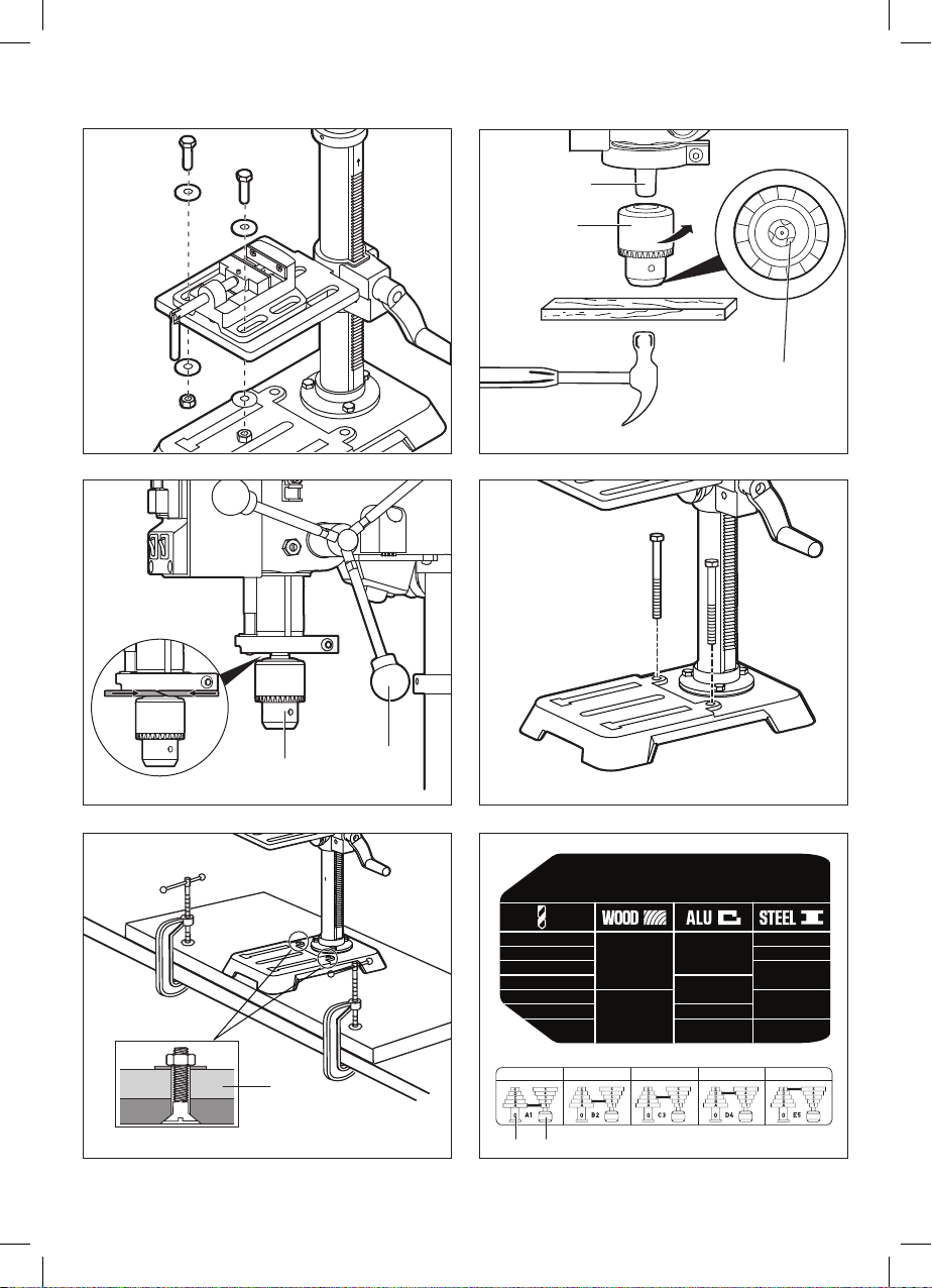
DRIL LING S PEED CHAR T
For use w ith high spe ed twist d rills.
10mm
13mm
2430 2430
2430
1800
1800
1800
1300
800 510
800
1300
Ø
*220-240V, 50HZ
510 RPM 800 RPM 1300 RPM 1800 RPM 2430 RPM
CHAR T
*220-240V,50HZ
6
5
F
G
J
K
H
M
W
V
Y
X
Z
AA
AB
S
T
U
L
QR
PN
AC
B
A C
D
E

6
7
8 9
W
M
H
K
G
K T U
X
AD
AF
AG
AH
AI
AJ AK AL
AF
AM
AO
AN

7
q
e
t
w
r
y
AP
AM
AM
AH
U
T
K
V
H
a

8
1.5mm
3mm
4mm
6mm
8mm
DRILLING SPEED CHART
For use with high speed twist drills.
10mm
13mm
2430 2430
2430
1800
1800
1800
1300
800 510
800
1300
Ø
510 RPM 800 RPM 1300 RPM 1800 RPM 2430 RPM
*220-240V, 50HZ
*220-240V, 50HZ
i
p
u
o
a
yb
W
G
G
T
AQ AR
AW
AQ

9
LASER
LIGHT
LASER
LIGHT
d
f
s
A
AR
S
QR AS
AR
AT
S
< 1.6 mm

10
LASER
LIGHT
4
k
h
j
l
g
AW
AV
M
K
U
L
XAU
BE
AX
MAY B
BA
AZ
F

11
LASER
LIGHT
c
b n
x
v
z
AB
AA
D
FE
BB
Z
Y
BB
BC
BB
BD

ACCESSORIES ➞WWW.SKIL.COM
12
LASER
LIGHT
m

13
AS Belt
AT Motor mount nuts
AU Bevel lock bolt
AV Gear teeth
AW Chuck jaw
AX Key storage slot
AY Housing set screw
AZ Laser adjustment knob
BA Laser set screw
BB Workpiece
BC Spindle sleeve
BD Pulley set screw
BE Locking pin
SAFETY
GENERAL POWER TOOL SAFETY WARNINGS
-WARNING: Read all safety warnings, instructions,
illustrations and specications provided with this
power tool. Failure to follow all instructions listed below may
result in electric shock, re and/or serious injury.
Save all warnings and instructions for future reference.
The term “power tool” in the warnings refers to your mains-
operated (corded) power tool or battery-operated (cordless)
power tool.
1) WORK AREA SAFETY
a) Keep work area clean and well lit. Cluttered or dark
areas invite accidents.
b) Do not operate power tools in explosive
atmospheres, such as in the presence of ammable
liquids, gases or dust. Power tools create sparks which
may ignite the dust or fumes.
c) Keep children and bystanders away while operating
a power tool. Distractions can cause you to lose control.
2) ELECTRICAL SAFETY
a) Power tool plugs must match the outlet. Never
modify the plug in any way. Do not use any adapter
plugs with earthed (grounded) power tools.
Unmodied plugs and matching outlets will reduce risk of
electric shock.
b) Avoid body contact with earthed or grounded
surfaces, such as pipes, radiators, ranges and
refrigerators. There is an increased risk of electric
shock if your body is earthed or grounded.
c) Do not expose power tools to rain or wet conditions.
Water entering a power tool will increase the risk of
electric shock.
d) Do not abuse the cord. Never use the cord for
carrying, pulling or unplugging the power tool. Keep
cord away from heat, oil, sharp edges or moving
parts. Damaged or entangled cords increase the risk of
electric shock.
e) When operating a power tool outdoors, use an
extension cord suitable for outdoor use. Use of a
cord suitable for outdoor use reduces the risk of electric
shock.
f) If operating a power tool in a damp location is
unavoidable, use a residual current device (RCD)
protected supply. Use of an RCD reduces the risk of
a
Bench Drill 1360
INTRODUCTION
• This tool is intended as a stationary machine for drilling
holes in wood, plastics, aluminium and steel
• Read and save this instruction manual 2
• This tool is not intended for professional use
• Only use the tool when correctly and completely
assembled (be aware that Skil cannot be hold
responsible for tool damage and/or personal injuries
resulting from the incorrect assembly of the tool)
• Check whether the packaging contains all parts as
illustrated in drawing 7
TECHNICAL DATA 1
TOOL ELEMENTS 6
A Pulley housing cover
B Laser housing
C Feed return spring and cover
D ON/OFF switch
E LED work light switch
F Laser switch
G Chuck
H Rack collar
J LED work light
K Support lock handle
L Bevel scale
M Chuck key
N Belt/pulley speed chart
P Pulley cover knob
Q Motor pulley
R Spindle pulley
S Tension lock knob
T Feed handle
U Crank handle
V Column support
W Base
X Table
Y Depth scale
Z Depth lock nut
AA Depth stop nut
AB Depth stop ring
AC Laser light
AD Column & rack assembly
AF Hex bolts
AG 3mm hex wrench
AH 4mm hex wrench
AI Vice
AJ Hex bolts for vice
AK Plain washers
AL Hex nuts
AM Rack
AN Crank handle hole
AO Table support
AP Worm shaft
AQ Spindle
AR Motor

14
f) Keep cutting tools sharp and clean. Properly
maintained cutting tools with sharp cutting edges are less
likely to bind and are easier to control.
g) Use the power tool, accessories and tool bits etc.
in accordance with these instructions, taking into
account the working conditions and the work to be
performed. Use of the power tool for operations dierent
from those intended could result in a hazardous situation.
h) Keep handles and grasping surfaces dry, clean
and free from oil and grease. Slippery handles and
grasping surfaces do not allow for safe handling and
control of the tool in unexpected situations.
5) SERVICE
a) Have your power tool serviced by a qualied repair
person using only identical replacement parts. This
will ensure that the safety of the power tool is maintained.
BENCH DRILL SAFETY WARNINGS
• The drill must be secured. A drill that is not properly
secured may move or tip over and may result in personal
injury.
• The workpiece must be clamped or secured to the
workpiece support. Do not drill pieces that are too
small to be clamped securely. Holding the workpiece
by hand during operation may result in personal injury.
• Do not wear gloves. Gloves may be entangled by the
rotating parts or chips leading to personal injury.
• Keep your hands out of the drilling area while the
tool is running. Contact with rotating parts or chips may
result in personal injury.
• Make sure the accessory is rotating before feeding
into the workpiece. Otherwise the accessory may
become jammed in the workpiece causing unexpected
movement of the workpiece and personal injury.
• When the accessory is jammed, stop applying
downward pressure and switch o the tool.
Investigate and take corrective actions to eliminate
the cause of the jam. Jamming can cause unexpected
movement of the workpiece and personal injury.
• Avoid generating long chips by regularly
interrupting downward pressure. Sharp metal chips
may cause entanglement and personal injuries.
• Never remove chips from the drilling area while
the tool is running. To remove chips, move the
accessory away from the workpiece, switch o the
tool and wait for the accessory to stop moving. Use
tools such as a brush or hook to remove chips.
Contact with rotating parts or chips may result in personal
injury.
• Accessories with speed ratings must be rated at
least equal to the maximum speed marked on the
power tool. Accessories running faster than their rated
speed can break and y apart.
• Keep bits clean and sharp. Sharp bits minimize
stalling. Dirty and dull bits may cause misalignment of the
material and possible operator injury.
• Restrain any loose clothing, jewellery, long hair, etc., that
may become entangled in the bit.
• Use recommended speed for drill accessory and
workpiece material.
• Be sure drill bit or cutting tool is securely locked in
the chuck.
• Be sure chuck key is removed from the chuck before
connecting to power source or turning power on.
electric shock.
3) PERSONAL SAFETY
a) Stay alert, watch what you are doing and use
common sense when operating a power tool. Do not
use a power tool while you are tired or under the
inuence of drugs, alcohol or medication. A moment
of inattention while operating power tools may result in
serious personal injury.
b) Use personal protective equipment. Always wear
eye protection. Protective equipment such as a dust
mask, non-skid safety shoes, hard hat, or hearing
protection used for appropriate conditions will reduce
personal injuries.
c) Prevent unintentional starting. Ensure the switch
is in the o -position before connecting to power
source and/or battery pack, picking up or carrying
the tool. Carrying power tools with your nger on the
switch or energising power tools that have the switch on
invites accidents.
d) Remove any adjusting key or wrench before turning
the power tool on. A wrench or a key left attached to
a rotating part of the power tool may result in personal
injury.
e) Do not overreach. Keep proper footing and balance
at all times. This enables better control of the power tool
in unexpected situations.
f) Dress properly. Do not wear loose clothing or
jewellery. Keep your hair and clothing away from
moving parts. Loose clothes, jewellery or long hair can
be caught in moving parts.
g) If devices are provided for the connection of dust
extraction and collection facilities, ensure these are
connected and properly used. Use of dust collection
can reduce dust-related hazards.
h) Do not let familiarity gained from frequent use of
tools allow you to become complacent and ignore
tool safety principles. A careless action can cause
severe injury within a fraction of a second.
4) POWER TOOL USE AND CARE
a) Do not force the power tool. Use the correct power
tool for your application. The correct power tool will
do the job better and safer at the rate for which it was
designed.
b) Do not use the power tool if the switch does not turn
it on and o. Any power tool that cannot be controlled
with the switch is dangerous and must be repaired.
c) Disconnect the plug from the power source and/
or remove the battery pack, if detachable, from
the power tool before making any adjustments,
changing accessories, or storing power tools. Such
preventive safety measures reduce the risk of starting the
power tool accidentally.
d) Store idle power tools out of the reach of children
and do not allow persons unfamiliar with the power
tool or these instructions to operate the power tool.
Power tools are dangerous in the hands of untrained
users.
e) Maintain power tools and accessories. Check for
misalignment or binding of moving parts, breakage
of parts and any other condition that may aect the
power tool’s operation. If damaged, have the power
tool repaired before use. Many accidents are caused
by poorly maintained power tools.

15
ADDITIONAL SAFETY WARNINGS
• Do not work materials containing asbestos (asbestos
is considered carcinogenic)
• Dust from material such as paint containing lead, some
wood species, minerals and metal may be harmful
(contact with or inhalation of the dust may cause allergic
reactions and/or respiratory diseases to the operator or
bystanders); wear a dust mask and work with a dust
extraction device when connectable
• Certain kinds of dust are classied as carcinogenic
(such as oak and beech dust) especially in conjunction
with additives for wood conditioning; wear a dust
mask and work with a dust extraction device when
connectable
• Follow the dust-related national requirements for the
materials you want to work with
• Always check that the supply voltage is the same as the
voltage indicated on the nameplate of the tool
• Never use the tool when the cord is damaged; it must be
replaced by a specially prepared cord available through
the service organization.
• Connect this earthed power tool only to a properly
earthed power supply system; ensure that socket
and extension cable have a functional protective
conductor
• Use completely unrolled and safe extension cords with a
capacity of 16 Amps (U.K. 13 Amps)
• Inspect the extension cord periodically and replace it, if
damaged
AFTER USE
• Lift or support the tool during transportation with both
hands m.
RESIDUAL RISKS
Even when the product is used as prescribed, it is still
impossible to completely eliminate certain residual risk
factors.The operator should pay particular and additional
attention to these points in order to reduce the risk of serious
personal injury.
• Injury to hearing – Wear suitable ear protection and limit
exposure.
• Injury to sight – Wear protective eye shields or goggles
when using the product.
• Injury caused by vibration – Limit exposure and follow the
instructions on risk reduction in this manual.
• Respiratory injury from dust created by operating the
product – Wear suitable protection depending on type
of dust.
WHEN CONNECTING NEW 3-PIN PLUG (U.K. ONLY):
• Do not connect the blue (= neutral) or brown (= live) wire
in the cord of this tool to the earth terminal of the plug
• If for any reason the old plug is cut o from the cord
of this tool, it must be disposed of safely and not left
unattended
EXPLANATION OF SYMBOLS ON TOOL
2Read the instruction manual before use
3Wear protective glasses and hearing protection
4Do not dispose of electric tools and batteries together
with household waste material
5Laser radiation. Do not stare into beam. Class 2 laser
product.
USE
• Assembly
-attach the column to the base W with 3 hex bolts AF 8
• Adjust the table or depth stop to avoid drilling into
the table. Shut o the power, remove the drill bit, and
clean the table before leaving machine.
• Avoid direct eye exposure when using the laser guide.
• Always ensure the laser beam is aimed at a surface
without reective properties. Shiny reective materials
are not suitable for laser use.
• Never place your ngers in a position where they
could contact the drill or other cutting tool if the
workpiece should unexpectedly shift.
• Never perform any operation by moving the head or
table with respect to one another. Do not turn the motor
switch on or start any operation before checking that the
head and table support lock handle is clamped tight to
column and head and table support collars are correctly
positioned.
• Before engaging the ON/OFF switch, make sure
the belt guard is down and the chuck is installed
properly.
• Always disconnect plug from power source before
making any adjustment or changing any accessory.
• Always disconnect plug from power source before
transporting the tool.
• If the power supply cord is damaged, it must be
replaced only by the manufacturer or by an authorised
service centre to avoid risk.
• Store idle tools. When not in use, tools should be stored
in a dry locked-up place, out of reach of children.
• Allow the tool to cool down after a continuous use of 10
minutes (S₂ 10 min.)
LASER SAFETY RULES
• The laser radiation used in the product is Class 2 with
maximum ≤1mW and 650nm wavelengths. Do not stare
into the laser beam. Failure to comply with the rules could
result in serious personal injury.
• Do not stare into beam during operation.
• Do not project the laser beam directly into the eyes of
others. Serious eye injury could result.
• Do not place the laser in a position that may cause
anyone to stare into the laser beam intentionally or
unintentionally.
• Do not use optical tools to view the laser beam.
• Do not operate the laser around children or allow children
to operate the laser.
• Do not attempt to repair the laser device by yourself.
• Do not attempt to change any parts of the laser device
by yourself.
• Any repairs must only be carried out by the laser
manufacturer or authorized service agent.
• Do not replace the laser with a dierent type.
• Do not remove or deface warning labels. Removing
labels increases the risk of exposure to radiation.
• Use of controls or adjustments or performance of
procedures other than those specied herein may result
in hazardous radiation exposure.
• The use of optical instruments with this product will
increase eye hazard.
• Do not use tinted glasses to enhance the laser light.
Tinted glasses will reduce the overall vision for the
application and interfere with the normal operation of the
tool.
• Never aim the beam at a work piece with a reective
surface. Bright shiny reective sheet steel or similar
reective surfaces are not recommended for laser use.
Reective surfaces could direct the beam back toward
the operator or bystanders.

16
p The mounting board should be of sucient size
to avoid tipping while bench drill is in use. Any good
grade plywood or chipboard with a 19 mm thickness is
recommended.
-mark holes on surface where bench drill is to be
mounted using holes in bench drill base as a template
for hole pattern
-drill holes through mounting surface
-place bench drill on mounting surface, aligning holes
in the base with holes drilled in the mounting surface
-insert bolts (not included) and tighten them securely
with lock washers and hex nuts (not included)
If lag bolts are used, make sure they are long enough
to go through holes in bench drill base and material the
bench drill is being mounted to. If machine bolts are
used, make sure bolts are long enough to go through
holes in bench drill, the material being mounted to, and
the lock washers and hex nuts.
! all bolts should be inserted from the top. Install
the lock washers and hex nuts from the underside
of the workbench.
Once the bench drill is securely mounted on a sturdy
surface:
-check for vibration when the motor is switched ON
-adjust and retighten the mounting hardware as
necessary
-check the table assembly to assure smooth movement
up and down the column
-check to assure that the spindle shaft moves smoothly
• Changing speeds and belt placement
The spindle speed is determined by the location of the
belt on the pulleys inside the head assembly. The speed
chart alocated on the cover inside the head assembly
shows the recommended speed and pulley conguration
for each drilling operation.
To change the pulley conguration: s
-open pulley housing cover A
-loosen the tension lock knob S
-pull the motor AR as close to the bench drill head as
possible
-remove the belt AS
-reposition the belt according to the speed chart a
-retighten the tension lock knob S
• Spindle speeds
The spindle speed chart is provided inside the pulley
housing cover. See a.
• Align the belt pulleys
-check the alignment of the pulleys with a straight edge
(not included) d
-if the pulleys are NOT aligned, loosen the belt tension
lock knob S to release belt tension f
-loosen the two motor mount nuts AT, and lower or
raise the motor AR until the pulleys are aligned
! the height dierence between the two pulleys
shall not exceed 1.6 mm.d
-tighten the motor mount nuts AT to maintain the
position f
-lock the motor AR for the proper belt tension and
tighten the tension lock knob
! never operate bench drill with pulley housing
cover open
• Adjusting the table
1. To raise or lower the table: g
-loosen the set screw in the rack collar H to remove the
rack collar H and the rack AM
-insert the table support lock handle K into the threaded
hole at the rear of the table support 9
-insert the rack AM into the geared groove of the table
support with the arrow on one end of the rack AM
pointing up and the teeth on the rack AM facing out q
-make sure the worm shaft AP on the inside of the table
support is engaged with the teeth of the rack AM, and
the table support sit at the centre of the rack AM w
-slide the assembled parts down together onto the
column, and insert the bottom edge of the rack AM into
the lip of the column support V q
-install the collar H bevel side down over the rack AM
w
!make sure there is enough clearance to allow
the table to rotate around the column. The collar
must sit loosely over rack and not angled on the
column. To avoid column or collar damage, only
tighten the set screw enough to keep collar in
place
-insert the crank handle U onto the worm shaft AP, and
tighten it e
-position the table X in the same direction as the base
W, and tighten the table support lock handle K
-install the head assembly onto the top of the column,
align it with the base W and the table X, and tighten
the two set screws with the hex wrench AH
-assemble the feed handle T t
! one or two of the feed handle rods may be
removed if an unusually shaped workpiece
interferes with handle rotation. It is recommended
to securely tighten the feed handle rods with an
adjustable wrench
-install the vice if necessary according to your work ya,
yb
• Installing/removing the chuck
1. To install u:
-inspect and clean the spindle AQ and the taper hole in
the chuck G
-open the chuck jaws AW and fully recess them inside
the chuck G
-seat the chuck G on the spindle AQ by placing a block
of wood under the chuck and tapping the wooden
block with a hammer or rubber mallet
! to avoid damaging the chuck, make sure the jaws
are completely recessed into the chuck. Do not
use a metal hammer directly to drive the chuck
into the spindle
2. To remove i:
-lower the chuck G to the lowest position
-place two wedges (not included) between the chuck
G and the shoulder of the spindle and apply pressure
as the arrows in 18 indicate. Pressure needs to be
increased gradually and symmetrically
! to avoid possible damage, be prepared to catch
the chuck as it falls
• Mounting tool on working surface
If the bench drill is to be used in a permanent location,
secure it to a workbench or other stable surface. o
If the bench drill is to be used as a portable tool, fasten
it permanently to a mounting board that can easily
be clamped to a workbench or other stable surface.

17
laser housings B
2. loosen the laser set screws BA on both sides
3. rotate the laser adjustment knobs AZ until the two
lines intersect where the drill meets the scrap wood.
DO NOT stare directly at the laser lines.
4. tighten the laser set screws
5. re-attach the housings and re-tighten the set screws
• ON/OFF switch z
-press the ON button to turn the bench drill on
-press the OFF button to turn the bench drill off
! in case of current interruption or when the plug is
accidentally pulled out, the tool will not restart on
its own
• Positioning the table and workpiece BB x
-lock the table X to the column at a position so the tip of
the drill bit is just above the top of the workpiece BB
-always place a backup material (scrap wood) on the
table X beneath the workpiece BB. This will prevent
splintering or heavy burring on the underside of the
workpiece BB. To keep the backup material from
spinning, it must be positioned against the left side of
the column.
! to prevent the workpiece BB or backup material
from being thrown while drilling, you MUST
position the workpiece BB against the left side
of the column. If the workpiece BB or the backup
material is not long enough to reach the column,
clamp them to the table X to brace the workpiece
BB. Failure to secure the workpiece BB could
result in personal injury.
-use appropriate means of support for overhanging
workpiece BB
! to reduce the risk of injury, make sure the chuck
key M is removed from the chuck G before starting
any drilling operation
• Drilling to a specic depth
Drilling a blind hole (not all the way through workpiece) to
a given depth can be done two ways:
1. Workpiece method
-mark the desired depth of the hole on the side of the
workpiece BB v
-with the ON/OFF switch D OFF, bring the drill bit down
until the tip is even with the mark
-hold the feed handles T at this position
-rotate the depth stop nut AA until it meets the depth
stop ring AB.cThen release the handle T.
-keep the stop nut AA stationary, lower the depth lock
nut Z to lock the stop nut AA.cThe chuck G and the
drill bit will now be stopped at the distance selected on
the depth scale Y.
2. Depth scale method
-with the ON/OFF switch D OFF, turn the feed handles
T until the drill bit tip slightly touches the top of the
workpiece BB c
-hold the feed handles T in that position
-rotate the depth stop nut AA until it meets the depth
stop ring AB.cThen release the handle T.
-keep the stop nut AA stationary, lower the depth lock
nut Z to lock the stop nut AA.cThe chuck G and
drill bit will now drill into the workpiece BB only to the
distance selected on the depth scale Y.
3. Drilling a hole
-using a centre punch or a sharp nail, make an
-loosen the table support lock handle K and turn the
crank handle U until the table X is at the desired height
-tighten the lock handle before drilling
2. To rotate the table:
-loosen the table support lock handle K and rotate the
table U around the column to the desired position
-tighten the lock handle K before drilling
3. To tilt the table: h
The table support has a predrilled hole with a locking pin
BE inserted for locking the table into a predrilled 0° bevel
angle.
-tighten the nut on the locking pin BE to release the pin
from the table support. This pin will be needed when
placing the table back to its 0 degree setting from the
table support.
-loosen the bevel lock bolt AU
! to prevent injury, be sure to hold the table X and
table arm assembly, so it will not swivel or tilt.
-tilt the table, aligning the desired angle measurement
to the zero line opposite the scale L
-tighten the bevel lock bolt AU
-to return the table to its original position, loosen
the bevel lock bolt AU. Return the table X to the 0°
position.
-return nut on locking pin to the outside end of threads.
Gently tap locking pin until it is seated in the mating
hole of the table bracket. Hand tighten nut.
• Installing drill bits j
-place the chuck key M into the side keyhole of the
chuck G, meshing the gear teeth AV
-turn the chuck key M to open the chuck jaws AW
-insert a drill bit into the chuck G far enough to obtain
maximum gripping of the chuck jaws AW
-center the drill bit in the chuck jaws AW before nal
tightening of the chuck G
-use the chuck key M for the nal tightening to make
sure the drill bit will not slip while drilling
! To reduce the risk of injury, only use the chuck key
M provided with this bench drill or a duplicate of
it. This chuck key M is self-ejecting and will “pop”
out of the chuck G when you let go. This action is
designed to help prevent throwing of the chuck
key M from the chuck G when power is turned
“ON”. Store the chuck key M in the key storage
slot AX next to the feed hub when not in use. kDo
not use any other key as a substitute; order a new
one if damaged or lost.
! to reduce the risk of injury, make sure the chuck
key M is removed from the chuck G before starting
any drilling operation
• LED work light z
-switch on/o LED work light J by pressing switch E
• Laser lines
-switch on/o laser lines by pressing switch F z
To check/adjust the alignment of the laser lines l:
-mark an “X” on a piece of scrap wood
-insert a small drill bit into the chuck G and align its tip
to the intersection of the lines of the “X”
-secure the board to the table
-turn on the laser switch F and verify the laser lines
align with the “X” on the scrap wood
-if the laser lines do not align, they need to be adjusted:
1. remove the housing set screws AY on each of the

18
MAINTENANCE / SERVICE
! to avoid accidents always disconnect the tool from
the power supply before cleaning or performing
any maintenance
• Periodically inspect the entire product for damaged,
missing, or loose parts such as screws, nuts, bolts,
caps, etc. Tighten securely all fasteners and caps and
do not operate this product until all missing or damaged
parts are replaced.
• If the tool should fail despite the care taken in
manufacturing and testing procedures, repair should
be carried out by an after-sales service centre for SKIL
power tools
-send the tool undismantled together with proof of
purchase to your dealer or the nearest SKIL service
station (addresses as well as the service diagram of the
tool are listed on www.skil.com)
• Be aware that damage due to overload or improper
handling of the tool will be excluded from the warranty
(for the SKIL warranty conditions see www.skil.com or
ask your dealer)
• Your SKIL tool has been properly lubricated and is ready
to use. The ball bearings in the spindle and the V-belt
pulley assembly are greased and permanently sealed.
-pull the spindle down band oil the spindle sleeve BC
moderately with SAE No. 20 or No. 30 oil, or WD 40
every three months
• Should you feel an unusually high level of vibration, the
pulleys may not be tightly secured on the motor and/or
spindle shafts.
-to make sure the pulleys are properly seated and tight,
locate the set screw BD on each of the pulleys
-tighten each set screw BD n
• Frequently blow out or vacuum any dust or metal chips
that accumulate in and on the motor, pulley housing,
table, and work surface.
! the tool may be cleaned most eectively with
compressed dry air
• Always keep tool and cord clean (especially the
ventilation slots at the back-end of the motor housing)
! always wear safety goggles when cleaning tools
with compressed air. The switches must be kept
clean and free of foreign matter. Do not attempt
to clean by inserting pointed objected through
openings.
• A coat of furniture paste wax applied to the table,
column, and machined parts of the base will help to
keep these surfaces clean.
• Store the tool indoors in a place that is inaccessible to
children. Keep away from corrosive agents.
! certain cleaning agents and solvents damage
plastic parts. Some of these are: gasoline, carbon
tetrachloride, chlorinated cleaning solvents,
ammonia and household detergents that contain
ammonia.
ENVIRONMENT
• Do not dispose of electric tools, batteries,
accessories and packaging together with household
waste material (only for EU countries)
-in observance of European Directive 2012/19/EC
on waste of electric and electronic equipment and
its implementation in accordance with national law,
indentation in the workpiece BB where you want to drill
-turn on the laser switch F and align the intersection of
laser lines with the indentation
-turn the ON/OFF switch D ON and pull down on the
feed handles T with only enough effort to allow the
drill to cut
! feeding too slowly might cause the drill bit to burn
! feeding too rapidly might stop the motor AR,
causing the belt AS or drill bit to slip, tearing the
workpiece BB loose, or breaking the drill bit
! when drilling metal, it will be necessary to
lubricate the tip of the drill bit with metal drilling
oil to prevent it from overheating
APPLICATION ADVICE
• Drilling speeds
Important factors when determining the best drilling
speed:
-type of material
-size of the hole to be drilled
-type of drill bit or cutter
-desired quality of the cut
! smaller drill bits require greater speed than large
drill bits, while softer materials require greater
speed than harder materials
• Drilling metal
-use metal-piercing twist drill bits
-it is always necessary to lubricate the tip of the drill
with oil to prevent overheating the drill bit
-all metal workpieces should be clamped down
securely. Any tilting, twisting, or shifting causes a
rough drill hole, and increases the potential of drill bit
breakage
-never hold a metal workpiece with your bare hands.
The cutting edge of the drill bit may seize the
workpiece and throw it, causing serious injury. The
drill bit will break if the metal piece suddenly hits the
column
-if the metal is at, clamp a piece of wood under it to
prevent turning. If it cannot be laid at on the table,
then it should be blocked and clamped
• Drilling wood
-brad point bits are preferred. Metal piercing twist bits
may be used on wood
-do not use auger bits. They turn so rapidly that they lift
the workpiece off the table and whirl it around
-always protect the drill bit by positioning the table
so the drill bit will enter the center hole when drilling
through the workpiece
-to prevent splintering, feed slowly when the bit is about
to cut through to the backside of the workpiece
-to reduce splintering and protect the point of the bit,
use scrap wood as a backing or a base block under
the workpiece
• Feeding the bit
-pull down on the feed handles with only enough force
to allow the drill bit to cut
-feeding too rapidly might stall the motor, cause the belt
to slip, damage the workpiece, or break the drill bit
-feeding too slowly will cause the drill bit to heat up and
burn the workpiece

19
T Bras de cabestan
U Manivelle
V Socle de colonne
W Socle
X Tableau
Y Échelle de profondeur
Z Écrou de blocage de la profondeur
AA Écrou de butée de profondeur
AB Bague de butée de profondeur
AC Sortie laser
AD Assemblage colonne et crémaillère
AF Boulons hexagonaux
AG Clé hexagonale de 3 mm
AH Clé hexagonale de 4 mm
AI Étau
AJ Boulons hexagonaux pour étau
AK Rondelles plates
AL Écrous hexagonaux
AM Crémaillère
AN Trou de la manivelle
AO Support de table
AP Arbre à vis sans n
AQ Broche
AR Moteur
AS Ceinture
AT Écrous du support moteur
AU Boulon de blocage du biseau
AV Dents d’engrenage
AW Mors de mandrin
AX Fente de rangement des clés
AY Vis de blocage du boîtier
AZ Bouton de réglage du laser
BA Vis de blocage du laser
BB Pièce à usiner
BC Manchon de broche
BD Vis de blocage de la poulie
BE Goupille de verrouillage
SÉCURITÉ
CONSIGNES DE SÉCURITÉ GÉNÉRALES POUR L’OUTIL
ÉLECTRIQUE
-AVERTISSEMENT : Lisez toutes les consignes
de sécurité, les instructions, les illustrations et les
spécications de sécurité fournies avec cet outil
électrique. Le non-respect des consignes gurant ci-
dessous peut provoquer un choc électrique, un incendie et/
ou des blessures graves.
Conservez tous les avertissements et instructions pour
pouvoir vous y référer ultérieurement.
Le terme « outil électrique » utilisé dans les consignes de
sécurité désigne votre outil électrique fonctionnant sur le
secteur (laire) ou sur batterie (sans l).
1) SÉCURITÉ DE L’AIRE DE TRAVAIL
a) Maintenez l’aire de travail propre et bien éclairée.
Les endroits sombres ou désordonnés augmentent les
risques d’accident.
b) N’utilisez pas les outils électriques dans des
atmosphères explosives, par exemple en présence
electric tools that have reached the end of their life
must be collected separately and returned to an
environmentally compatible recycling facility
-symbol 4will remind you of this when the need for
disposing occurs
NOISE
• Measured in accordance with EN 62841 the sound
pressure level of this tool is 67 dB(A) and the sound
power level 80 dB(A) (uncertainty K = 3 dB)
• The noise emission level has been measured in
accordance with a standardised test given in EN 62841;
it may be used to compare one tool with another and
as a preliminary assessment of exposure to noise when
using the tool for the applications mentioned
-using the tool for different applications, or with different
or poorly maintained accessories, may signicantly
increase the exposure level
-the times when the tool is switched off or when it is
running but not actually doing the job, may signicantly
reduce the exposure level
b
Perceuse à colonne 1360
INTRODUCTION
• Cet outil est conçu comme une machine stationnaire
pour le perçage de trous dans le bois, le plastique,
l’aluminium et l’acier
• Lisez et conservez ce manuel d’instructions 2
• Cet outil n’est pas conçu pour un usage professionnel.
• N’utilisez l’outil que lorsqu’il est correctement
et complètement assemblé (Skil ne peut être tenu
responsable des dommages causés à l’outil et/ou
des blessures corporelles résultant d’un assemblage
incorrect de l’outil)
• Vériez que toutes les pièces montrées sur le schéma
sont contenues dans l’emballage 7
CARACTÉRISTIQUES TECHNIQUES 1
PIÈCES DE L’OUTIL 6
A Capot de la poulie
B Boîtier du laser
C Ressort de rappel et couvercle
D Interrupteur marche/arrêt
E Interrupteur de lampe de travail LED
F Interrupteur laser
G Mandrin
H Collier de crémaillère
J Lampe de travail à LED
K Poignée de blocage du support
L Graduation du biseau
M Clé de mandrin
N Tableau des vitesses de la courroie/poulie
P Bouton du couvercle de la poulie
Q Poulie du moteur
R Poulie de broche
S Bouton de blocage de la tension

20
une alimentation électrique alors que son interrupteur
marche/arrêt est dans la position marche favorise les
accidents.
d) Retirez toutes les clés de réglage et de serrage
avant de mettre l’outil électrique en marche. Une
clé de réglage ou de serrage laissée sur une pièce
rotative de l’outil électrique peut provoquer des blessures
corporelles.
e) N’essayez pas de travailler des endroits diciles
à atteindre. Conservez en permanence des appuis
des pieds solides et un bon équilibre. Cela permet un
meilleur contrôle de l’outil électrique en cas de situations
inattendues.
f) Portez une tenue adaptée. Ne portez pas de
vêtements amples ni de bijoux. Maintenez vos
cheveux et vos vêtements éloignés des pièces mobiles.
Les vêtements amples, les bijoux et les cheveux longs
peuvent se prendre dans les pièces mobiles.
g) Si un outil est conçu pour être utilisé avec des
dispositifs d’extraction et de récupération des
poussières, veillez à ce que ces dispositifs soient
raccordés et correctement utilisés. L’utilisation de
dispositifs de récupération des poussières permet de
réduire les risques liés aux poussières.
h) Veillez à ne pas devenir trop sûr de vous et ne
cessez pas de respecter les principes de sécurité
même si vous vous sentez familiarisé à l’utilisation
de l’outil. La négligence peut provoquer des blessures
graves en une fraction de seconde.
4) UTILISATION ET ENTRETIEN DE L’OUTIL
ÉLECTRIQUE
a) Ne forcez pas l’outil électrique. Utilisez l’outil
électrique qui convient au travail que vous voulez
eectuer. L’utilisation d’un outil qui convient au travail à
eectuer permet de réaliser ce travail plus ecacement,
avec une sécurité accrue et au rythme pour lequel l’outil
a été conçu.
b) N’utilisez pas l’outil électrique si son interrupteur
marche/arrêt ne permet pas de l’allumer et de
l’éteindre. Tout outil électrique qui ne peut pas être
contrôlé par son interrupteur marche/arrêt est dangereux
et doit être réparé.
c) Débranchez le câble de l’alimentation électrique
et/ou retirez la batterie, si amovible, de l’outil
électrique avant tout réglage ou changement
d’accessoire, et avant de ranger l’outil électrique.
Cette mesure de sécurité préventive réduit le risque de
démarrage accidentel de l’outil électrique.
d) Rangez les outils électriques non utilisés hors de
portée des enfants. N’autorisez pas les personnes
non familiarisées avec l’outil électrique ou ce
manuel d’utilisation à l’utiliser. Les outils électriques
sont dangereux dans les mains de personnes
inexpérimentées.
e) Entretenez les outils électriques et les accessoires.
Inspectez-les pour vérier qu’aucune pièce mobile
n’est grippée ou mal alignée, qu’aucune pièce n’est
cassée, et pour tout autre problème qui pourrait
aecter leur fonctionnement. Si un outil électrique
est endommagé, il doit être réparé avant d’être
réutilisé. Beaucoup d’accidents sont dus à des outils
électriques mal entretenus.
f) Veillez à ce que les accessoires de coupe restent
de liquides, gaz ou poussières inammables. Les
outils électriques génèrent des étincelles pouvant
enammer les poussières et les vapeurs.
c) Veillez à ce que les enfants et les autres personnes
restent éloignés pendant l’utilisation d’un outil
électrique. Un moment d’inattention peut vous faire
perdre le contrôle de l’outil.
2) SÉCURITÉ ÉLECTRIQUE
a) La che de l’outil électrique doit correspondre
à la prise électrique. Ne modiez jamais la prise
de quelque manière que ce soit. N’utilisez jamais
d’adaptateur de prise avec les outils électriques
pourvus d’une mise à la terre ou à la masse.
Les ches non modiées et les prises électriques
appropriées réduisent le risque de choc électrique.
b) Évitez tout contact physique avec des surfaces
mises à la terre ou mises à la masse, telles que
tuyaux, radiateurs, fours et réfrigérateurs. Il y a un
risque accru de choc électrique si votre corps est relié à
la terre ou à la masse, directement ou indirectement.
c) N’exposez pas les outils électriques à la pluie ou à
un environnement mouillé. Si de l’eau pénètre dans un
outil électrique, cela accroît le risque de choc électrique.
d) Prenez soin du câble d’alimentation. N’utilisez
jamais le câble d’alimentation pour porter, tirer
ou débrancher l’outil électrique. Veillez à ce que
le câble d’alimentation n’entre jamais en contact
avec de l’huile, des pièces mobiles, des arêtes
tranchantes, et ne soit jamais exposé à de la
chaleur. Les câbles d’alimentation endommagés ou
emmêlés augmentent le risque de choc électrique.
e) Quand vous utilisez un outil électrique en extérieur,
utilisez une rallonge électrique adaptée à un usage
en extérieur. L’utilisation d’une rallonge conçue pour un
usage en extérieur permet de réduire le risque de choc
électrique.
f) Si vous êtes obligé d’utiliser un outil électrique
dans un endroit humide, utilisez une alimentation
protégée par un dispositif diérentiel à courant
résiduel (DDR). L’utilisation d’un DDR réduit le risque de
choc électrique.
3) SÉCURITÉ DES PERSONNES
a) Restez vigilant, soyez attentif à ce que vous faites et
faites preuve de bon sens lors de l’utilisation d’un
outil électrique. N’utilisez pas un outil électrique
quand vous êtes fatigué ou sous l’emprise de
l’alcool, de stupéants ou de médicaments. Un
moment d’inattention pendant l’utilisation des outils
électriques peut provoquer des blessures corporelles
graves.
b) Utilisez des équipements de protection individuelle.
Portez toujours une protection oculaire. L’utilisation
d’équipements de protection appropriés aux conditions
de travail, tels que masque antipoussières, chaussures
de sécurité antidérapantes, casque et protections
auditives, permet de réduire les risques de blessures
corporelles.
c) Évitez les démarrages accidentels. Vériez que
l’interrupteur marche/arrêt est dans la position
arrêt avant de brancher l’outil dans une prise
électrique et/ou une batterie, de le saisir ou de le
transporter. Transporter un outil électrique les doigts
sur son interrupteur marche/arrêt ou le brancher dans
Table of contents
Languages:
Other Skil Drill manuals